CPC Definition - Subclass F03G
This place covers:
Spring, gravity, inertia or like motors. Devices or mechanisms for producing power, e.g. mechanical or electric power, from muscle energy, or solar energy, or not otherwise provided for, or using energy sources not otherwise provided for.
Attention is drawn to the following places, which may be of interest for search:
Arrangements in connection with power supply in vehicles from force of nature | |
Electric propulsion with power supply in vehicles from force of nature |
In this place, the following terms or expressions are used with the meaning indicated:
Motor | mechanism for producing mechanical power from potential energy of solid bodies |
This place covers:
Spring-motors characterised by shape or material of spring.
Spring-motors with cup springs, membrane springs, ring springs or gas springs.
Spring-motors with nanosprings.
This place covers:
Spring-motors with spiral springs.
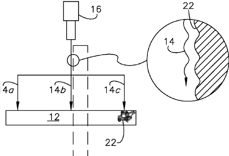
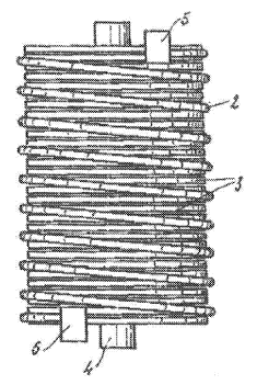
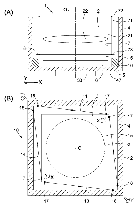
Illustrative example of subject matter classified in this group, note spiral spring 14:
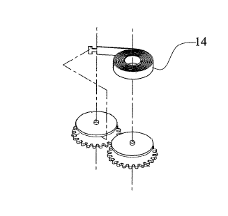
The expression "coil spring" can refer either to a spiral spring (F03G 1/022) or to a helical spring (F03G 1/024). Search and classify according to the respective embodiments and the specific spring geometry concerned.
This place covers:
Spring-motors with helical springs.
Illustrative example of subject matter classified in this group:
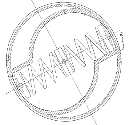
The expression "coil spring" can refer either to a spiral spring (F03G 1/022) or to a helical spring (F03G 1/024). Search and classify according to the respective embodiments and the specific spring geometry concerned.
This place covers:
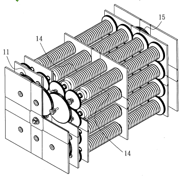
Spring-motors with torsion springs.
Illustrative example of subject matter classified in this group:
This place covers:
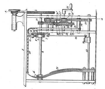
Spring-motors with leaf-springs.
Illustrative example of subject matter classified in this group:
This place covers:
Spring-motors with two or more springs, e.g. spiral springs or leaf springs or combinations thereof and being connected for example in series or parallel.
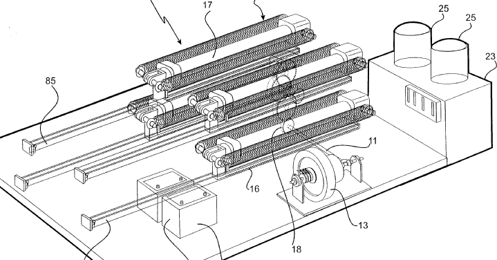
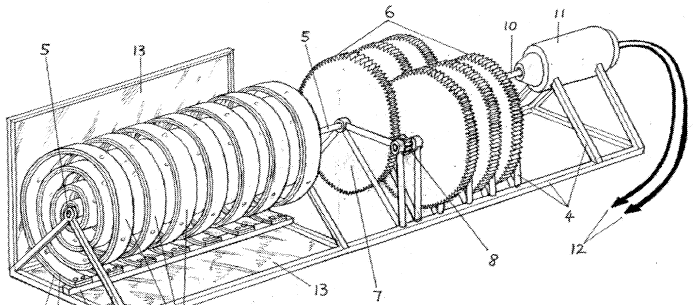
Illustrative example of subject matter classified in this group:
This place covers:
Spring-motors applying bimetals.
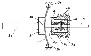
Illustrative example of subject matter classified in this group:
This place covers:
Spring-motors with rubber springs.
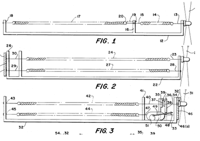
Illustrative example of subject matter classified in this group:
This place covers:
Other parts or details of spring-motors, e.g. speed-control, decoupling or damping mechanisms thereof.
Illustrative example of subject matter classified in this group:
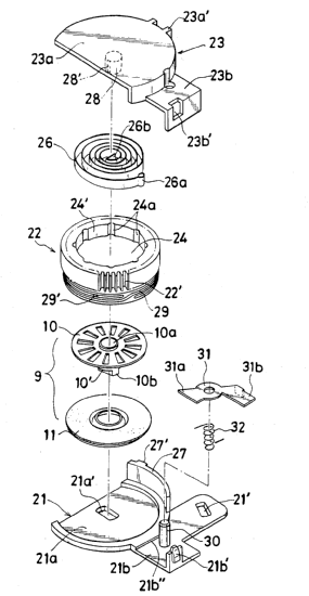
This place covers:
Other specific parts or details for winding of spring-motors.
Illustrative example of subject matter classified in this group:
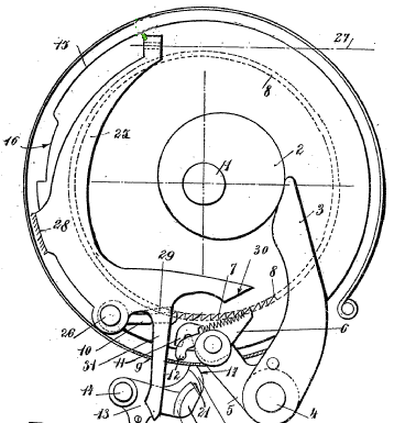
This place covers:
Other parts or details of spring-motors for producing output movement other than rotary, e.g. vibratory.
Illustrative example of subject matter classified in this group:
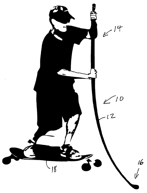
The illustrative example above shows a propulsion device (10) which includes an elongated pole (12) made of flexible and elastic material such as carbon fibre. A first end (14) of the pole (12) is formed to be suitable for grasping by a human hand. The second end (16) may be formed to be suitable for placing on a firm surface for propelling a wheeled vehicle such as a skateboard (18).
Illustrative example of subject matter classified in this group:
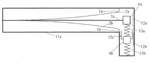
Reference is made to the beam 3a and the movement up and down by moving masses.
This place covers:
Motors driven by gravity or inertia force, e.g. driven by solid falling bodies like bowls, or by solid falling materials like sand, or by out of balance bodies like pendulums, or by the change of the orientation of the rotation axis of a rotating body.
Examples of places in relation to which this place is residual:
Motors driven by falling liquid or by waves, e.g. hydraulic turbines, or wave power plants, or tidal power plants |
This place covers:
Wheels cooperating with solid falling bodies coming from outside of the wheel and causing an imbalance on and a rotation of the wheel.
Illustrative example of subject matter classified in this place:

This place does not cover:
Driven by sand or like fluent solid material |
Attention is drawn to the following places, which may be of interest for search:
Alleged perpetua mobilia | |
Continuously converting gravity into usable power | |
Using an imbalance for increasing torque or saving energy |
This place covers:
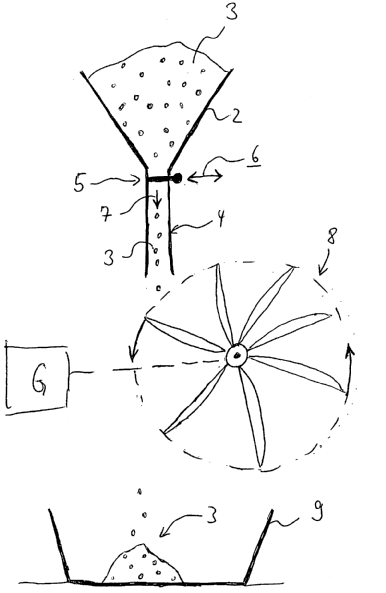
Sand-mill type wheels co-operating with solid falling bodies coming from outside of the wheel and causing an unbalance on and a rotation of the wheel.
Illustrative example of subject matter classified in this group:
This place covers:
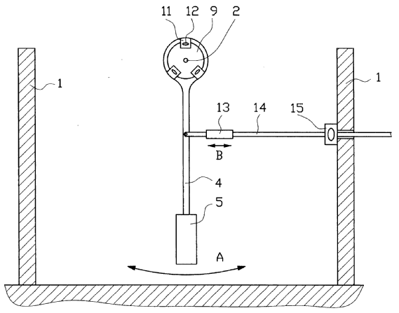
Other motors, e.g. gravity or inertia motors, using pendulums.
Illustrative example of subject matter classified in this group:
This place covers:
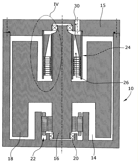
Other motors, e.g. gravity or inertia motors, using flywheels.
Illustrative example of subject matter classified in this group:
Attention is drawn to the following places, which may be of interest for search:
Devices for producing mechanical power from muscle energy other than of endless-walk type using flywheels | |
Prime movers comprising a combustion engine and a flywheel | |
Rotary bodies comprising rolls, drums, discs or the like | |
Construction of rotary bodies to resist centrifugal force | |
Suppression of vibrations in flywheels | |
Rotary transmissions with mechanical accumulators, e.g. intermittently connected flywheels | |
Balancing of load in an AC network using dynamo-electric machines coupled to flywheels | |
Additional mass for increasing inertia, e.g. flywheels | |
For power storage |
Devices for producing mechanical power from muscle power and using flywheels to be classified only in F03G 5/06, its subgroups and F03G 5/086.
This place covers:
Deviation of the flywheel axis of a motor using a flywheel for making use of gyroscopic effects, like precession or nutation.
Illustrative example of subject matter classified in this group:
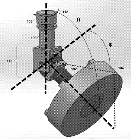
Method and apparatus for a gimbal propulsion system
Attention is drawn to the following places, which may be of interest for search:
Cosmonautic vehicles using inertia or gyroscopic effect | |
Gyroscopes in general |
This place covers:
Motors using the reduction of potential energy of a weight for generating a rotational movement.
Illustrative example of subject matter classified in this group:
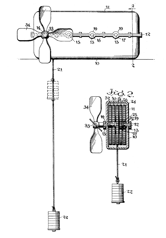
This place covers:
The wheel is unbalanced and thus the wheel rotation is generated by moving the gravity point of one or several masses within the wheel between a position close to the wheel rotation axis and a position far from the wheel rotational axis. For the movement of the mass or masses, a specific input of energy is required.
Illustrative examples of subject matter classified in this place:
1.
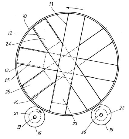
Figure 1 illustrates a device for converting mechanical energy into electrical energy, in which a weight (23-26) is arranged so as to be periodically displaceable by mechanical, hydraulic or pneumatic means against the direction of gravity, in which further at least one duct (11-14) extending in a diametral direction and arranged in a circular frame rotatable about its middle transverse axis is provided. In this arrangement the frame (10) is drive connected at the circumference to at least one electrical generator (21, 22).
2.
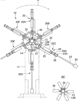
Figure 2 illustrates a rotary device of the unbalanced wheel type with weights actuated by hydraulic motors.
If the movement of the gravity point of the respective mass or masses is effected by solar energy, only group F03G 6/002 is to be considered.
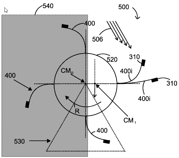
The figure illustrates a solar-powered device (500) that includes a central hub (520); plural curved blades (400) attached to the central hub (20); and plural weights (310) connected to the plural curved blades (400). A curved blade (400i) of the plural curved blades (400) has a proximal end attached to the central hub (520) and a distal end attached to a corresponding weight (310), and wherein the curved blade (400i) is made of a material that changes its geometry when exposed to solar energy.
Attention is drawn to the following places, which may be of interest for search:
Alleged perpetua mobilia | |
Continuously converting gravity into usable power | |
Using an imbalance for increasing torque or saving energy |
This place covers:
The potential energy previously stored in a weight is converted into rotational energy, in particular for driving a generator, e.g. during high demand of electricity, by moving down the weight. The process is reversed, e.g. during low demand of electricity and the generator is used as an electric motor that rotates a shaft and shifts up the respective weight.
Illustrative example of subject matter classified in this group:
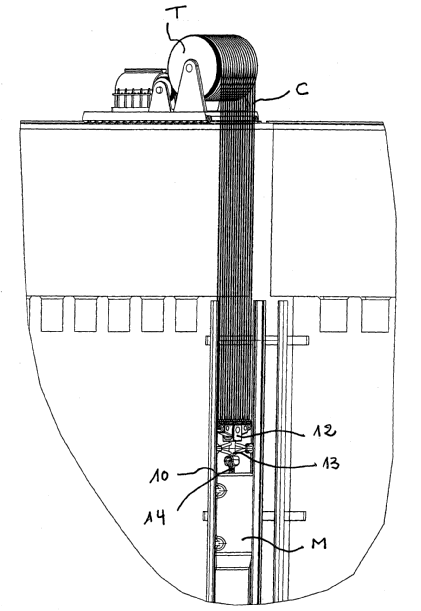
Attention is drawn to the following places, which may be of interest for search:
Muscle activated potential energy storage devices | |
Pump storage power plants | |
Rotary transmissions with mechanical accumulators | |
Systems for storing electric energy specially adapted for power networks |
This place covers:
Weight or inertia motors specifically adapted for pumping or conveying fluids.
This place covers:
Illustrative example of subject matter classified in this group:
The following illustrations show the purpose: To permit a propulsion plate to be transferred to an arbitrary position on a plane by installing each pair of vibration generating apparatuses opposed in the perpendicular directions on a same propulsion plate and adjusting the number of revolution of each eccentric motor.
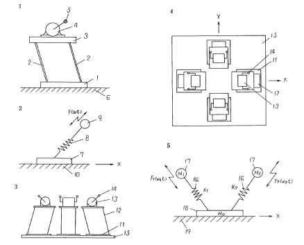
Attention is drawn to the following places, which may be of interest for search:
Vibrators involving rotary unbalanced masses | |
Vibrating plate compactors |
Attention is drawn to the following places, which may be of interest for search:
Geothermal collectors |
In this place, the following terms or expressions are used with the meaning indicated:
Steam | Water in the gas phase |
Vapour | Substance, not being steam, in the gas phase |
Working fluid | The fluid that converts heat into mechanical work in a turbine |
Source fluid | The fluid in thermal contact with the geothermal well. This fluid is either in direct fluid and thermal contact with the well or only in thermal contact with the well. |
Rankine Cycle | During conversion of heat into mechanical work, a phase change of the working fluid is involved. |
Brayton cycle | Open or closed thermodynamic cycle of a constant pressure heat engine, e.g. of the gas turbine |
Stirling Cycle | Closed, reversible and regenerative thermodynamic cycle with a gaseous working fluid |
This place covers:
Binary cycle plants whereby the source fluid is in contact with the geothermal well and whereby the working fluid forms separate circuits that are thermally connected to each other via a heat exchanger.
Illustrative example of subject matter classified in this group:
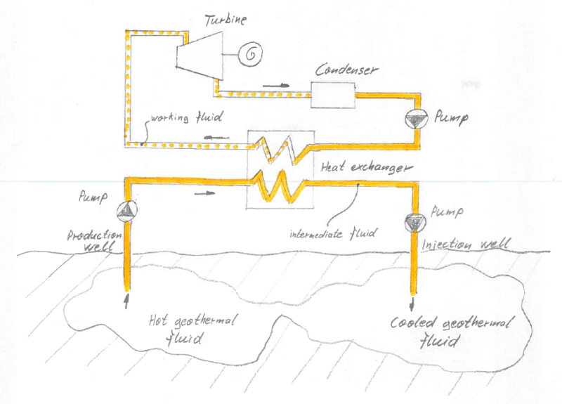
This place covers:
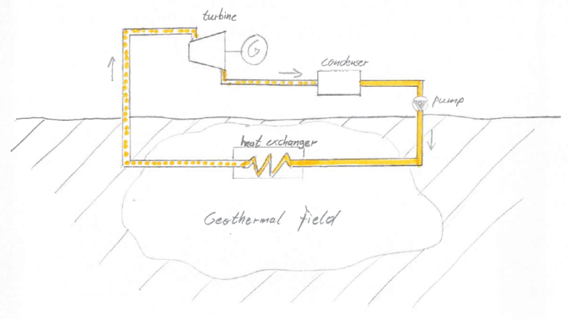
Single-cycle plants where the source fluid is the working fluid.
In such a single cycle power plant there is only one fluid cycle. This implies that the source fluid extracting the heat from the geothermal well and the working fluid typically driving a steam turbine are the same.
In this place, it is not relevant if the source fluid as such is in direct contact with the geothermal well rock or not. In this place, the source fluid can be either in direct contact with the rock or could flow through a piping that is only in thermal exchange with the rock.
Illustrative examples of subject matter classified in this place:
1.
2.
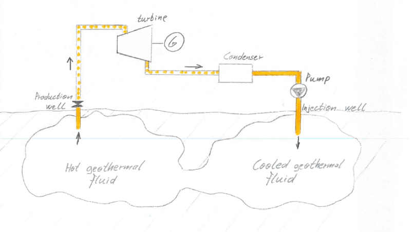
This place covers:
The geothermal collector with the source fluid is in contact with the geothermal well.
This place covers:
The source fluid in the geothermal collector is in fluid contact with the geothermal well.
Illustrative example of subject matter classified in this group:

This place covers:
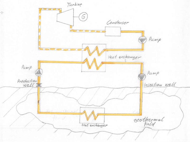
Closed-loop geothermal collectors. The source fluid flows through a piping that is in thermal exchange with the rock. There is no direct contact between the source fluid and (dry) rock in the geothermal well.
In this place, both closed-loop geothermal collectors being part of a binary-cycle-type (F03G 4/001) as well as of a single-cycle-type geothermal power plant (F03G 4/02) are covered.
Illustrative examples of subject matter classified in this place:
1. Closed-loop geothermal collector of the binary-cycle type

2. Closed-loop geothermal collector of the single-cycle type

This place covers:
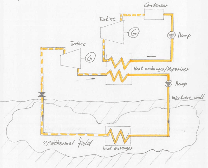
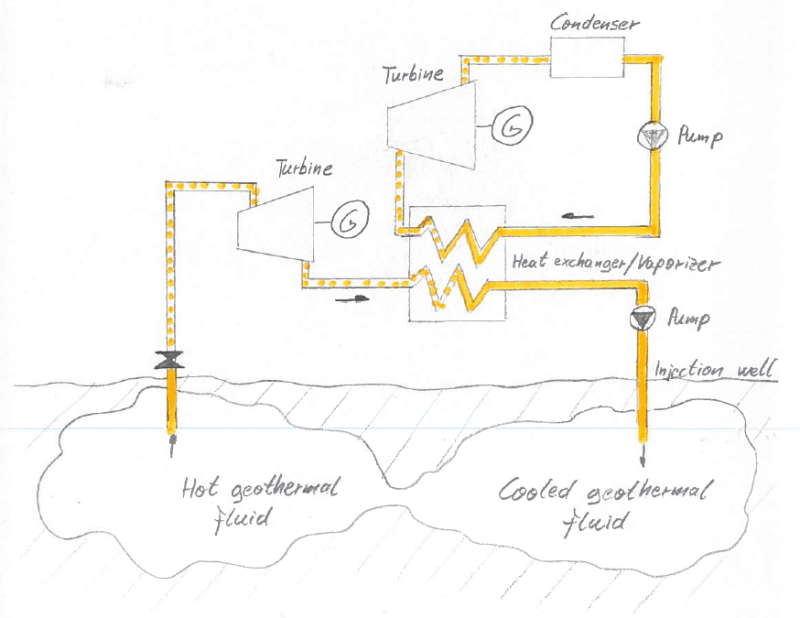
There are at least two working fluid circuits, which are fluidically separated but thermally connected via a heat exchanger.
Illustrative example of subject matter classified in this group:
This place covers:
The working fluid being subject to a phase change from liquid to vapour, e.g. water turning to steam.
This place covers:
An Organic Rankine Cycle uses an organic fluid, like CFC, HFC, HC, PFC, with a boiling point lower than the water boiling point.
In a Kalina cycle, the conversion of heat into mechanical power is realized by using a solution of two fluids with different boiling points, the most widely used combination being water and ammonia.
This place covers:
Illustrative examples of subject matter classified in this group:
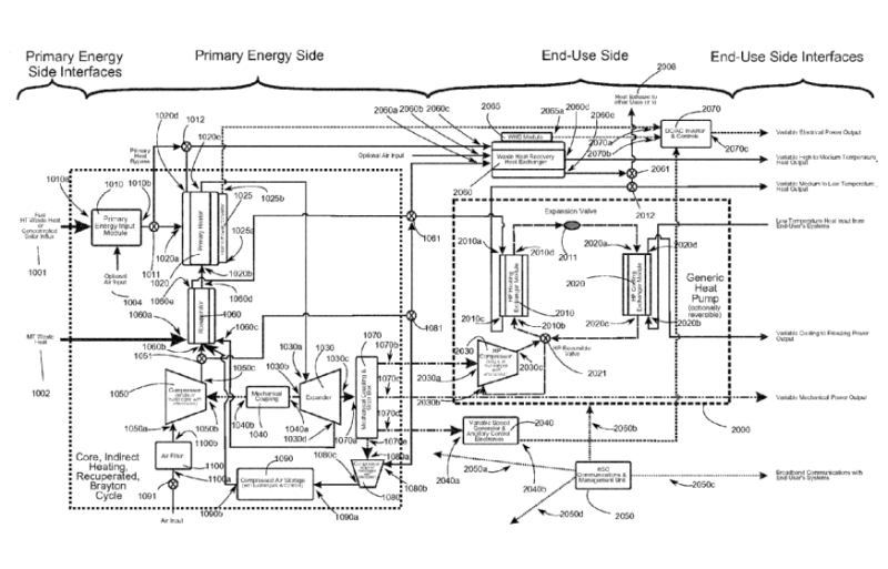
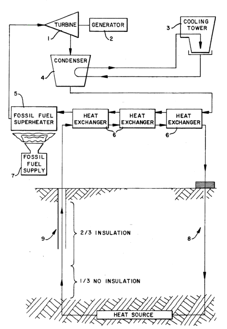
For combined geothermal power and solar power plants, search and classification in F03G 4/037 and F03G 6/0055 applies.
Attention is drawn to the following places, which may be of interest for search:
Hot or domestic water systems using heat pumps | |
Heat pumps |
This place covers:
Causing evaporation by lowering a fluid's pressure below its vapour pressure.
This place covers:
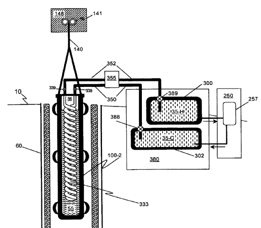
Geothermal power plants with thermal storage devices.
Illustrative example of subject matter classified in this group:
This place covers:
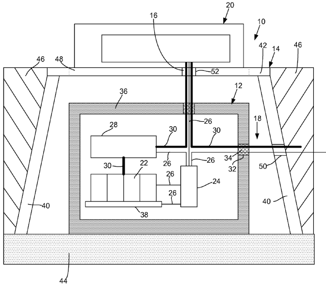
Geothermal power plants with non-thermal storage devices.
Illustrative example of subject matter classified in this group:
Attention is drawn to the following places, which may be of interest for search:
Geothermal plants with thermal storage devices | |
Gas turbine plants with means for storing compressed air | |
Storing energy using a fluid | |
Systems for storing electric energy specially adapted for power networks using storage of hydraulic energy | |
Systems for storing electric energy specially adapted for power networks using storage of pneumatic energy |
This place covers:
Treatment of accumulating brine (salt-water) or scale (chalky deposit caused by water evaporation).
Illustrative example of subject matter classified in this group:
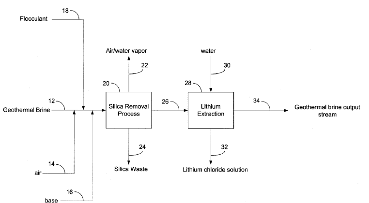
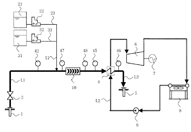
The following example shows a method for producing geothermal power using geothermal brines while producing a reduced silica and iron brine having improved injectivity. The resulting compositions include a composition with reduced silica, iron, and lithium having reduced quantity of total suspended solids.
Method for inhibiting scale and geothermal power generating device
This place covers:
Control or monitoring of geothermal power plants.
This place covers:
Safety arrangements of geothermal power plants.
This place covers:
Devices for producing mechanical power from human or animal muscle energy and being of the endless-walk type, e.g. treadmills, or other than of the endless-walk type, e.g. pedal generators.
Examples of places in relation to which this place is residual:
Driving cycles |
Attention is drawn to the following places, which may be of interest for search:
Charging batteries with a non-electric prime mover | |
Electric generator with motor driven by animals or vehicles |
This place covers:
Devices for producing mechanical power from muscle energy being of endless-walk type and used by humans or animals.
Illustrative example of subject matter classified in this group:
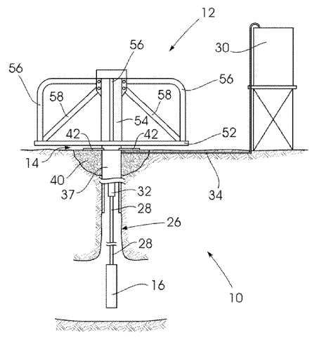
The following example shows a muscle-powered water pump installation which includes a drive formation (12) supported for rotation about a drive formation rotational axis by at least one animal or human, a water pump (16) drivingly connected to the drive formation for pumping water from a water supply in response to rotation of the drive formation, and an auxiliary rotary power take-off drivingly connected to the drive formation for providing rotational power in response to rotation of the drive formation.
This place covers:
Treadmills for producing mechanical power from muscle energy, these treadmills only being used by humans.
Illustrative example of subject matter classified in this group:
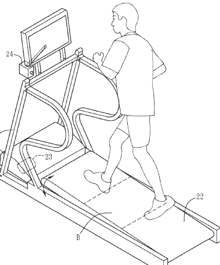
A sporting apparatus comprises a structure body, an endless belt, an electricity generating unit, a position sensing unit and a modulation unit for continuously outputting electricity as the sporting apparatus is continuously operated.
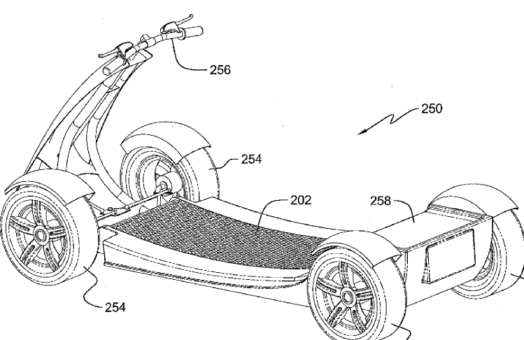
The figure illustrates a vehicle designs which derive their motive power from persons moving their legs on treadmill platforms built into the vehicle.
This place does not cover:
Horsemills or the like powered by animals |
This place covers:
Horsemills used by horses or any other animal for producing mechanical power from muscle energy.
Illustrative example of subject matter classified in this group:
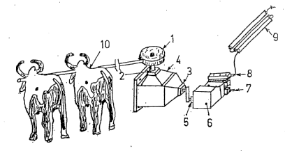
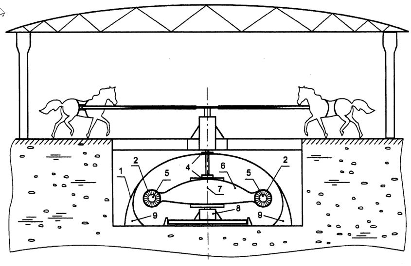
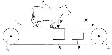
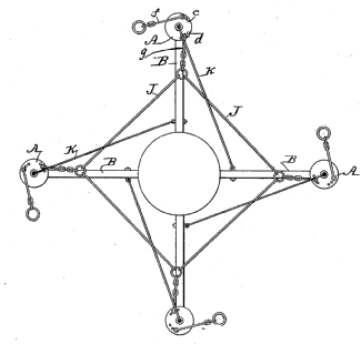
This place covers:
Illustrative example of subject matter classified in this group:
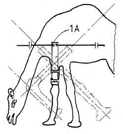
This place covers:
Devices for producing mechanical power from muscle energy other than of endless-walk type driven by animals.
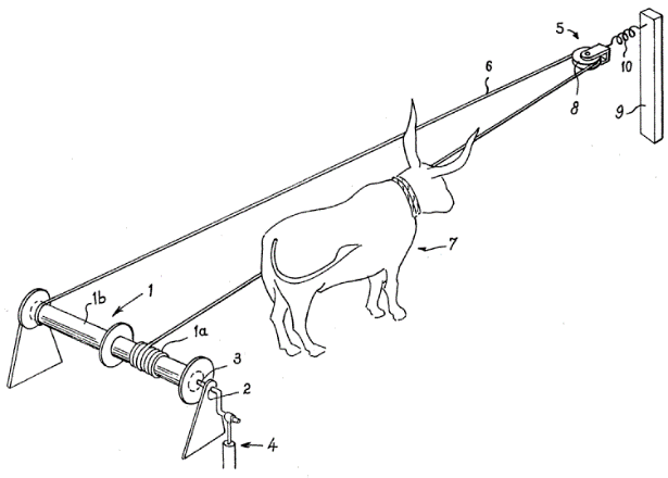
Illustrative example of subject matter classified in this group:
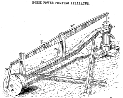
The following illustration shows an actuation device, particularly for a pump, using animal traction.
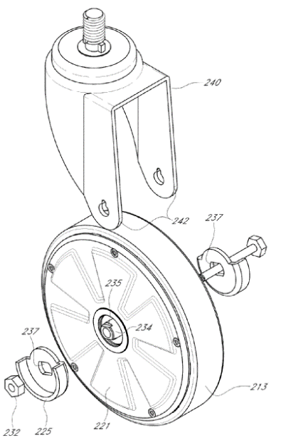
This place covers:
Devices for producing mechanical power from muscle energy other than of endless-walk type driven by humans.
Illustrative example of subject matter classified in this group:
The following illustration shows a system for managing electrical power generated by an electric generator placed on a human-propelled wheeled cart, i.e. shopping cart.
This place covers:
Devices for producing mechanical power from muscle energy other than of endless-walk type and being operated by the leg or foot/feet of humans.
Illustrative example of subject matter classified in this group:
The following illustration shows a foot-powered energy generator.
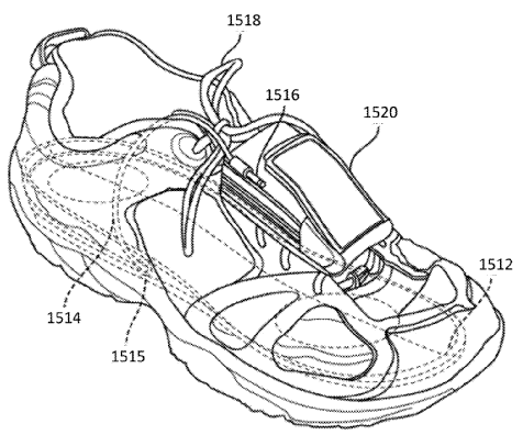
This place covers:
Illustrative example of subject matter classified in this group:
The following illustration shows an electricity-generation gymnasium bicycle.
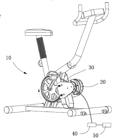
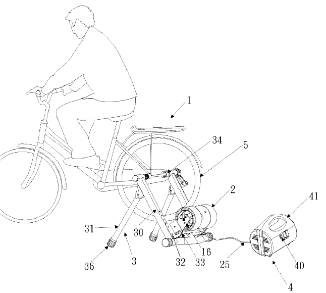
Attention is drawn to the following places, which may be of interest for search:
Exercising apparatus, the produced electric power being used as a source for other equipment |
This place covers:
Illustrative example of subject matter classified in this group:
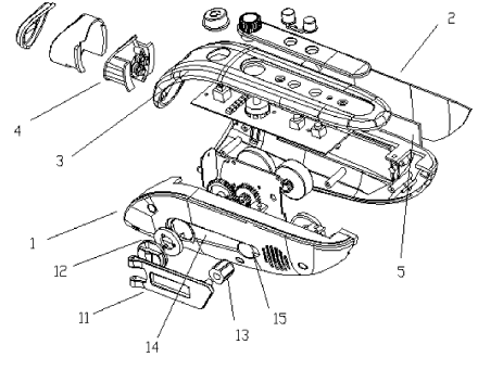
Hand-cranked charger
Attention is drawn to the following places, which may be of interest for search:
Self-winding caused by the movement of the watch | |
Electric power supply in watches |
This place covers:
Devices for producing mechanical power from muscle energy other than of endless-walk type driven by humans and having a combined motor-generator.
Illustrative example of subject matter classified in this group:
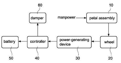
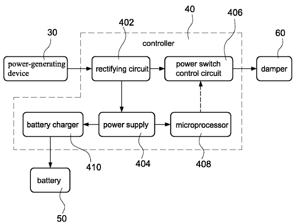
Illustrated is an electric bike with capability of self-charging. The electric bike is fixedly supported by supporting legs so as to be operated in a stationary point. A user steps on a petal assembly of the electric bike to drive a wheel to rotate. The electric bike further includes a power-generating device, a controller, a battery and a damper. The controller is used to receive a power source outputted by the power-generating device and convert the power source into a plurality of DC power sources to charge the battery. The damper consumes a portion of electricity generated by the power-generating device. With the above arrangement, the electric bike can be charged by itself while the user is exercising.
This place covers:
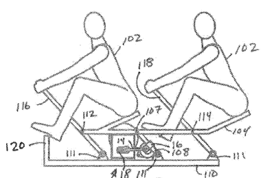
Illustrative example of subject matter classified in this group:
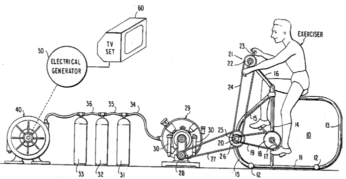
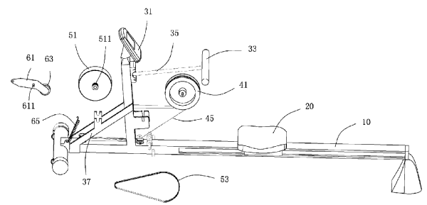
Exercise rowing machine with power generation
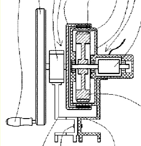
This place covers:
Devices for producing mechanical power from muscle energy using flywheels.
Illustrative example of subject matter classified in this group:
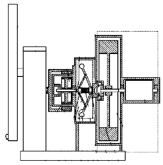
This place covers:
Devices for producing mechanical power from muscle energy using centrifugal or centripetal force.
Illustrative example of subject matter classified in this group:
This place covers:
Devices for producing mechanical power from muscle energy using potential energy storage.
Illustrative example of subject matter classified in this group:
This place covers:
Devices for producing mechanical power from muscle energy used for pumping or conveying a fluid.
Illustrative example of subject matter classified in this group:
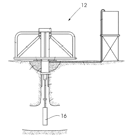
The following illustration shows a muscle-powered water pump installation which includes a drive formation (12) supported for rotation about a drive formation rotational axis by at least one animal or human, a water pump (16) drivingly connected to the drive formation for pumping water from a water supply in response to rotation of the drive formation, and an auxiliary rotary power take-off drivingly connected to the drive formation for providing rotational power in response to rotation of the drive formation.
This place covers:
Devices for producing mechanical power from muscle energy using springs.
Illustrative example of subject matter classified in this group:
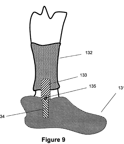
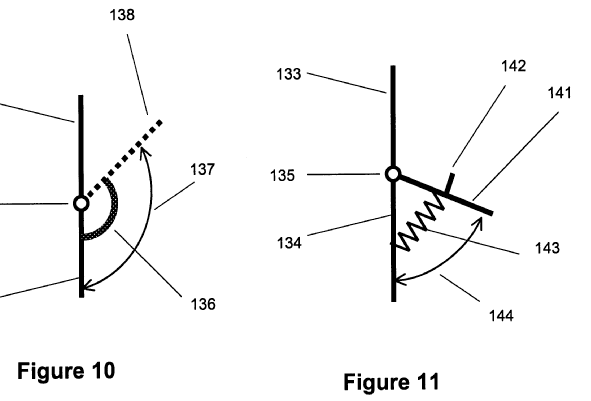
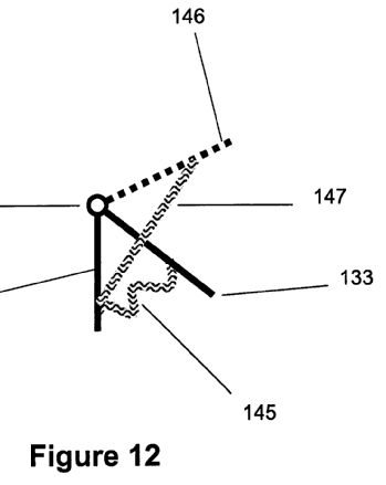
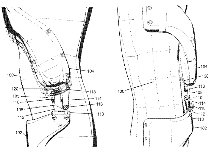
Figure 9 illustrates a schematic of an embodiment of a walk-assist device for use on an ankle.
Figures 10, 11 and 12 illustrate schematics of the embodiment of Figure 9 with a torsional spring, a linear spring and an elastic element, respectively.
This place covers:
Devices for producing mechanical power from solar energy, e.g. with photovoltaic cells, or solar collectors with or without concentration of solar rays, the devices using a single-state working fluid, e.g. Stirling cycle, or involving a phase change of the working fluid (Rankine cycle), e.g. a steam-water cycle.
Attention is drawn to the following places, which may be of interest for search:
Solar desalination | |
Gas-turbine plants with the working fluid being heated indirectly, e.g. by solar energy | |
Stirling cycle type engines | |
Up-wind power plants | |
Solar heat collectors | |
Machines using solar energy | |
Energy generation through solar thermal energy |
In this place, the following terms or expressions are used with the meaning indicated:
Steam | Water in the gas phase. |
Vapour | Substance, not being steam, in the gas phase |
Working fluid | The fluid that converts heat into mechanical work in a turbine. |
Heating fluid | The fluid in thermal contact with the solar collectors or concentrators. |
Rankine Cycle | During conversion of heat into mechanical work a phase change of the working fluid is involved. |
Brayton cycle | Open or closed thermodynamic cycle of a constant pressure heat engine, e.g. of the gas turbine. |
Stirling Cycle | Closed, reversible and regenerative thermodynamic cycle with a gaseous working fluid. |
This place covers:
Solar thermal power plant and with photovoltaic cells.
Illustrative example of subject matter classified in this group:

Attention is drawn to the following places, which may be of interest for search:
Pure photovoltaic installations |
This place covers:
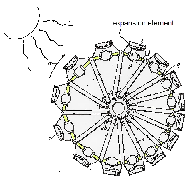
Solar power plants with expansion and contraction elements, no matter if there are means for concentrating the solar rays or not.
Illustrative example of subject matter classified in this group:
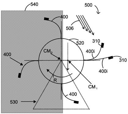
The figure illustrated above shows a solar-powered device (500) that includes a central hub (520); plural curved blades (400) attached to the central hub (520); and plural weights (310) connected to the plural curved blades (400). A curved blade (400i) of the plural curved blades (400) has a proximal end attached to the central hub (520) and a distal end attached to a corresponding weight (310), and wherein the curved blade (400i) is made of a material that changes its geometry when exposed to solar energy.
This place covers:
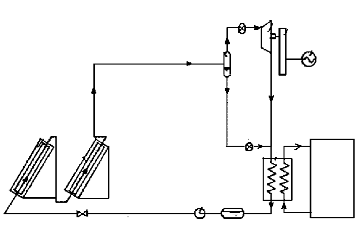
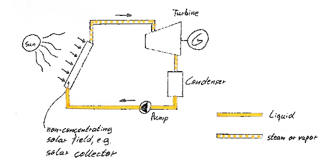
Devices for producing mechanical power from solar energy having a Rankine cycle and without means for concentrating the solar rays, e.g. solar collectors. There is only one fluid circuit for the collectors and the turbine.
Illustrative example of subject matter classified in this group:
This place does not cover:
Devices for producing mechanical power from solar energy with means for concentrating solar rays and having a Rankine cycle |
Documents dealing with solar power plants with a Rankine cycle that do not mention if the solar rays are concentrated or not are to be classified only under F03G 6/003 (single working fluid circuit) or F03G 6/005 (binary cycle plants with a heating fluid and a working fluid).
This place covers:
Devices for producing mechanical power from solar energy having an Organic Rankine cycle or a Kalina cycle and without means for concentrating the solar rays, e.g. solar collectors. There is only one fluid circuit for the collectors and the turbine.
An Organic Rankine cycle uses an organic fluid, like CFC, HFC, HC, PFC, with a boiling point lower than the water boiling point.
In a Kalina cycle, the conversion of heat into mechanical power is realized by using a solution of two fluids with different boiling points, the most widely used combination being water and ammonia.
This place covers:
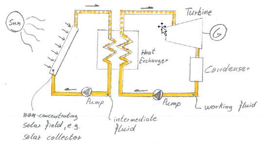
Devices for producing mechanical power from solar energy having a Rankine cycle and without means for concentrating the solar rays, e.g. with solar collectors. There are at least two fluid cycles involved (i.e. binary cycle). The heating fluid, sometimes also called the intermediate fluid, e.g. water or a molten salt, is the fluid transporting the heat from the solar field to at least one heat exchanger, e.g. a preheater or vaporizer, the heat exchanger transferring the heat to the separate working fluid cycle. The working mechanical/electrical power. The Rankine cycle refers to the working fluid circuit.
Illustrative example of subject matter classified in this group:
This place covers:
Devices for producing mechanical power from solar energy without solar concentration and having non-Rankine power cycles.
For combined geothermal power and solar power plants, search and classification in F03G 4/037 and F03G 6/0055 applies.
Attention is drawn to the following places, which may be of interest for search:
Stirling Cycle type engines |
This place covers:
Devices for producing mechanical power from solar energy using a single state working fluid, e.g. air or ammonia gas, with or without means for concentrating solar rays and with or without an intermediate fluid for heat transfer.
Illustrative example of subject matter classified in this group:
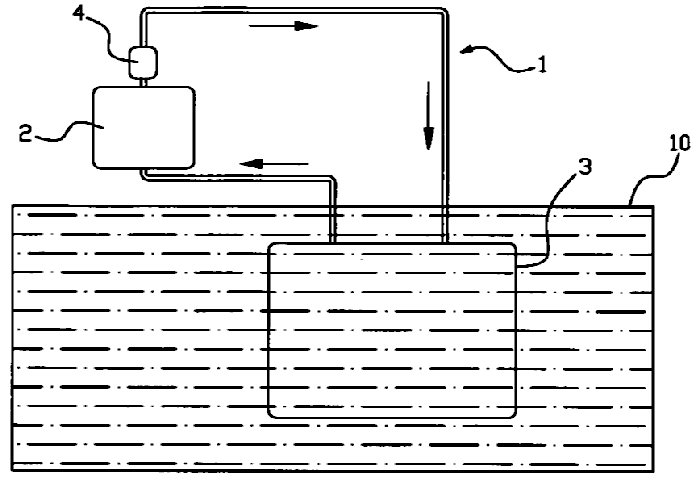
The following illustration showing an apparatus for generating electricity by using solar energy is provided. The main structure includes a circulation pipeline 1 and a hydroelectric generator 4. The circulation line 1 is filled with water or other convective water. The circulation line 1, partially submerged below the sea surface 10, is partially exposed above the sea surface 10. A portion of the circulation pipeline 1 submerged below the sea surface 10 forms a cooling water tank 3. A portion of the circulation pipeline 1 exposed above the sea surface 10 forms a heat-absorbing water tank 2 whose outer circumference is covered with a heat-absorbing layer. A water outlet is formed above the heat absorbing water tank 2, and a water inlet is formed below. A water turbine generator 4 is provided near the water outlet of the heat-absorbing water tank 2.
This place covers:
Devices for producing mechanical power from solar energy using a gaseous working fluid, e.g. a Stirling cycle, with or without means for concentrating solar rays and with or without an intermediate fluid for heat transfer.
Illustrative example of subject matter classified in this group:
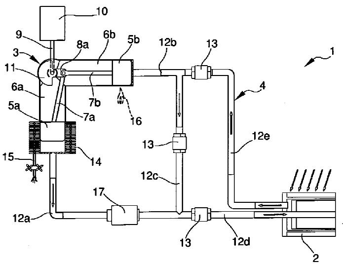
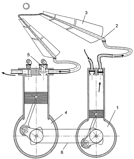
This place covers:
Solar up-wind tower power plants in the form of chimneys.
Illustrative example of subject matter classified in this group:
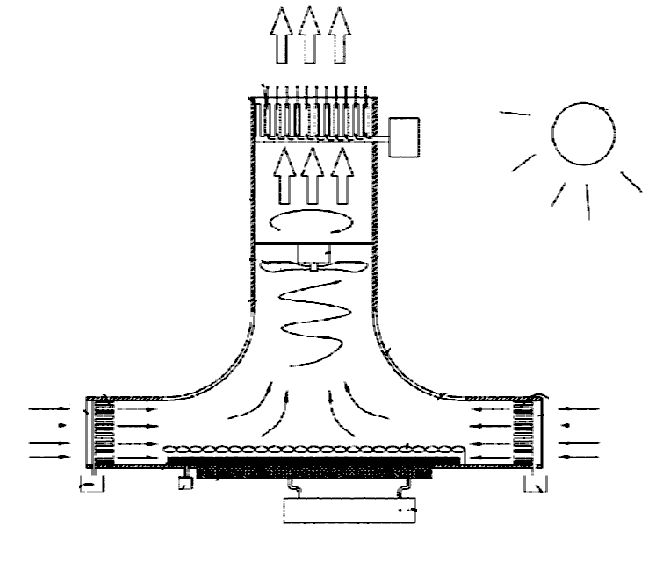
The tower concentrators under F03G 6/063 also use towers; these towers, however, are used to place the solar receivers or collectors on an elevated position in order to better receive the solar rays from the mirrors.
This place covers:
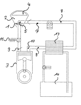
Devices for producing mechanical power from solar energy with means for concentrating solar rays.
Illustrative example of subject matter classified in this group:
Attention is drawn to the following places, which may be of interest for search:
Means for concentrating solar rays | |
Solar ray lenses |
This place covers:
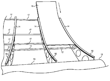
Solar power plants disclosed together with specific details of the parabolic linear concentrators.
Illustrative example of subject matter classified in this group:
Attention is drawn to the following places, which may be of interest for search:
Solar collectors with reflectors as concentrating elements |
This place covers:
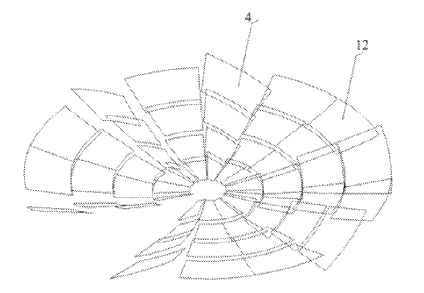
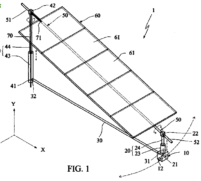
Solar power plants disclosed together with specific details of the parabolic point or dish concentrators.
Illustrative example of subject matter classified in this group:
Attention is drawn to the following places, which may be of interest for search:
Solar collectors with reflectors as concentrating elements |
This place covers:
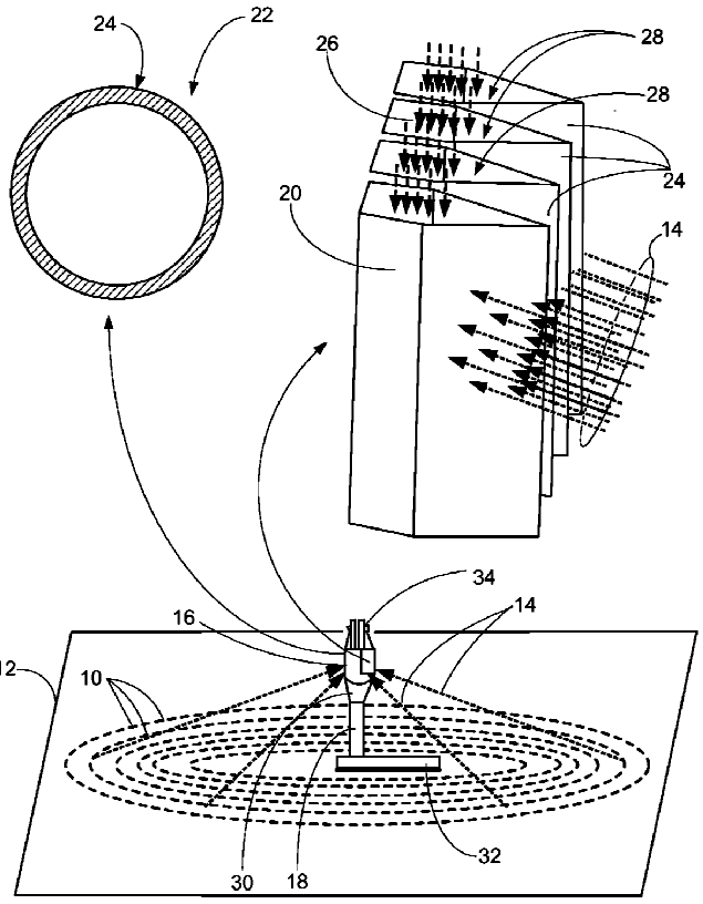
Solar power plants disclosed together with specific details of the tower concentrators. The towers are used to place the solar receivers or collectors on an elevated position in order to better receive the solar rays from the mirrors.
Illustrative example of subject matter classified in this group:
The upwind power plants under F03G 6/045 also use towers; these towers, however, are in the form of chimneys.
Attention is drawn to the following places, which may be of interest for search:
Solar tower or receivers |
This place covers:
Solar power plants with a gas turbine or Brayton cycle.
Illustrative example of subject matter classified in this group:
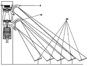
This place covers:
Devices for producing mechanical power from solar energy having a Rankine cycle and with means for concentrating the solar rays, e.g. parabolic linear or point concentrators. There is only one fluid circuit between the collectors and the turbine.
Illustrative example of subject matter classified in this group:
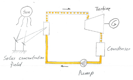
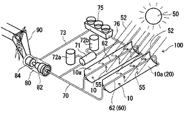
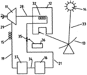
This place covers:
Devices for producing mechanical power from solar energy having an Organic Rankine cycle or a Kalina cycle and with means for concentrating the solar rays, e.g. parabolic linear or point concentrators. There is commonly only one fluid circuit between the collectors and the turbine.
An Organic Rankine cycle uses an organic fluid, like CFC, HFC, HC, PFC, with a boiling point lower than the water boiling point.
In a Kalina cycle the conversion of heat into mechanical power is realized by using a solution of two fluids with different boiling points, the most widely used combination being water and ammonia.
This place covers:
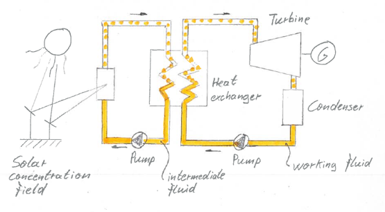
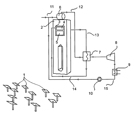
Devices for producing mechanical power from solar energy having a Rankine cycle and with means for concentrating the solar rays, e.g. with parabolic linear or point concentrators. There are at least two fluid cycles involved (i.e. binary cycle). The heating fluid, sometimes also called the intermediate fluid, e.g. water or a molten salt, is the fluid transporting the heat from the solar field to at least one heat exchanger, e.g. a preheater or vaporizer, the heat exchanger transferring the heat to the separate working fluid cycle. The working fluid is the fluid used in a working machine, e.g. a steam turbine, to generate the mechanical/electrical power. The Rankine cycle refers to the working fluid circuit.
Illustrative example of subject matter classified in this group:
This place covers:
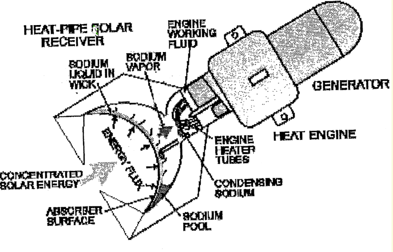
Devices for producing mechanical power from solar energy with solar concentration and having non-Rankine power cycles.
Illustrative example of subject matter classified in this group:
Attention is drawn to the following places, which may be of interest for search:
Stirling cycle type engines |
This place covers:
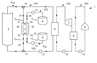
Devices for producing mechanical power from solar energy with thermal energy storage devices.
Illustrative example of subject matter classified in this group:
Attention is drawn to the following places, which may be of interest for search:
Heat storage plants |
This place covers:
Illustrative example of subject matter classified in this group:
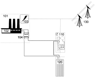
Illustrated is a combined thermal and compressed-gas energy conversion system comprising a compressed-gas energy conversion system configured for substantially isothermal storage and recovery of energy, a source of recovered thermal energy: and a heat-exchange subsystem in fluid communication with the compressed-gas energy conversion system and the source of recovered thermal energy. Optionally the source of recovered thermal energy comprises at least one of a fossil fuel power plant, a heat engine power plant, a solar thermal source, a geothermal source, an industrial process with waste heat, a heat pump, a heat source, a heat sink, or a source of environmentally chilled water.
Attention is drawn to the following places, which may be of interest for search:
Gas turbine plants with means for storing compressed air | |
Storing energy using a fluid | |
Systems for storing electric energy specially adapted for power networks using storage of hydraulic energy | |
Systems for storing electric energy specially adapted for power networks using storage of pneumatic energy |
This place covers:
Devices for producing mechanical power from solar energy with solar ponds for collecting the solar energy.
Illustrative example of subject matter classified in this group:

Waste salts and brines are disposed of by constructing salt water solar pond power plants, concentrating the waste salts and brines, and then introducing them into the heat storage layers of the solar ponds of the power plants. The basins in which such solar ponds are constructed are made deeper than needed to sustain operation of the power plant at its designed output, and after a deep basin is filled, the concentrated brine from the heat storage layer is available to construct another solar pond which is then available for storing additional waste salts. In concentrating the waste salts, sodium chloride will precipitate, and this material can be deposited at the bottom of the solar ponds to seal the same against leakage.
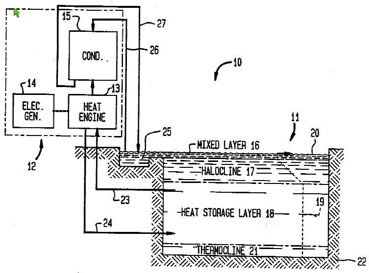
Method and apparatus for producing power from solar ponds
Attention is drawn to the following places, which may be of interest for search:
Salt gradient solar ponds |
This place covers:
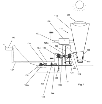
Devices for producing mechanical power from solar energy, the mechanical power used for pumping a fluid.
Illustrative example of subject matter classified:
This place covers:
Devices for producing mechanical power from solar energy using heat pumps. Heat pumps transfer thermal energy from a cold place to a warmer place, e.g. air conditioners or freezers.
Illustrative example of subject matter classified:
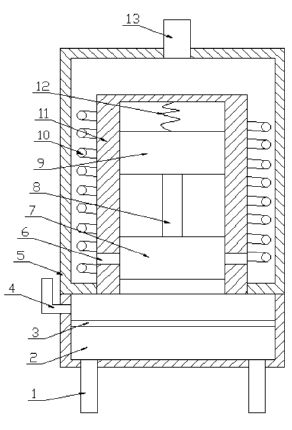
Solar heat pump for transforming solar energy into electrical energy
Attention is drawn to the following places, which may be of interest for search:
Hot or domestic water systems using heat pumps | |
Heat pumps |
This place covers:
Components, parts or details of solar power plants.
This place covers:
Components, parts or details of the heat transfer system of solar power plants.
This place covers:
Heat transfer fluids of the heat transfer system of solar power plants.
Illustrative example of subject matter classified:
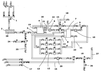
Facility for treating thermal oils in solar thermal plants
This place covers:
Use, composition or details of the molten salts used as heat transfer fluid in solar power plants.
Illustrative example of subject matter classified:
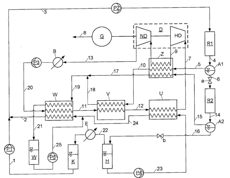
Operating solar thermal power plant with heat transfer medium circuit, comprises heating directly liquid, salt and melt comprehensive heat carrier by solar radiation, and cooling the working medium against in steam circuit of steam turbine.
Attention is drawn to the following places, which may be of interest for search:
Alkali salt compounds |
This place covers:
Details related to the solid-liquid phase change of the heat transfer fluid.
Illustrative example of subject matter classified:
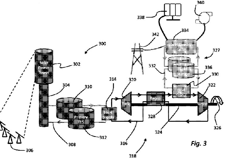
Concentrated solar power system, wherein the heat storage material is a phase change material which will undergo a phase change when the heat storage material is heated to an operational temperature.
This place covers:
Control or monitoring of solar power plants.
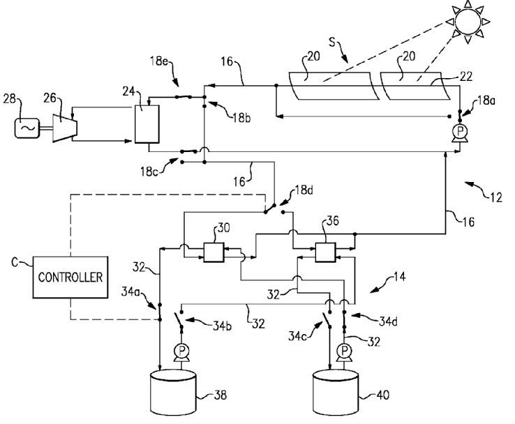
This place covers:
Features specifically related to the start-up control of solar power plants.
This place covers:
Features specifically related to the over-night operation of solar power plants.
Illustrative example of subject matter classified:
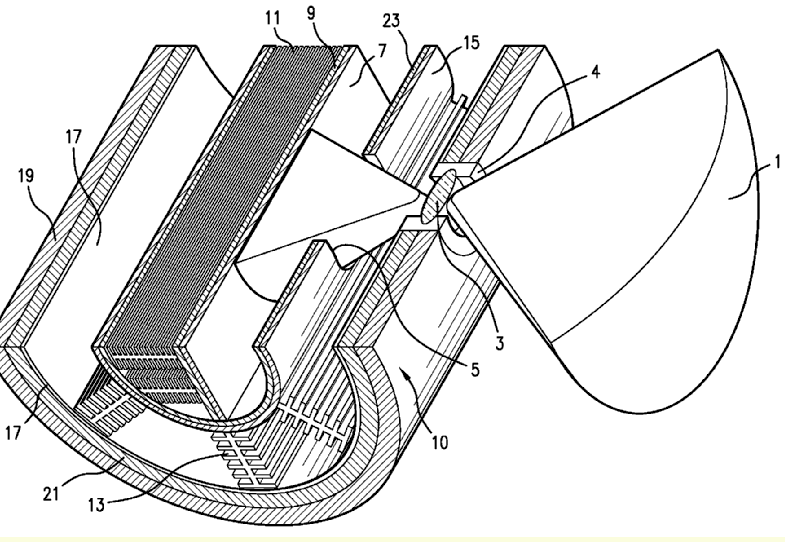
The figure above illustrates a solar chimney, comprising an enclosure defining a path for flow of a fluid to be heated, the enclosure containing a heat exchanger, a solar collector located outside the enclosure, a reservoir for storing a heat transfer fluid, and means for directing heat transfer fluid between the reservoir, the solar collector, and the heat exchanger, wherein, in a first position of the directing means, appropriate for use during daytime, heat transfer fluid can flow from the reservoir, then into the solar collector, then into the heat exchanger, and then back to the reservoir, and wherein, in a second position of the directing means, appropriate for use during nighttime, heat transfer fluid can flow from the reservoir, into the heat exchanger, and then back to the reservoir.
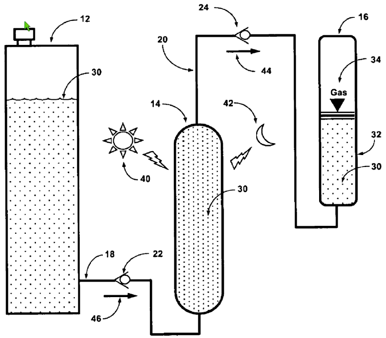
The figure above illustrates a thermal pump system energized by a daytime heating phase and a night time cooling phase associated with a naturally occurring environmental heating and cooling cycle that includes a hydraulic fluid source, a thermal fluid expansion chamber having a fixed internal volume, and a hydraulic accumulator at least partially filled by a compressible gas. A first unidirectional flow valve connected to a first duct permits flow only out of the hydraulic fluid source during the night time cooling phase. A second unidirectional flow valve connected to a second duct permits flow only out of the thermal fluid expansion chamber upon expansion of the hydraulic fluid trapped in the thermal fluid expansion chamber due to heating during the daytime heating phase. The thermal fluid expansion chamber has a thermally conductive wall communicating thermal energy from the naturally occurring heating and cooling cycle to the hydraulic fluid trapped in the fixed internal volume.
This place covers:
Features specifically related to safety arrangements of solar power plants.
This place covers:
Devices or mechanisms for producing mechanical power from vibrational energy, e.g. of a fluid or a machine, or from an electro-chemical process, or by using pressure differences or thermal differences occurring in nature, or from expansion or contraction of bodies.
This place does not cover:
Flexible endoscopes using shape memory elements | |
Electrothermal relays making use of shape memory materials |
Attention is drawn to the following places, which may be of interest for search:
Microstructural devices or systems, e.g. micromechanical devices | |
Perpetuum mobile cycles | |
Alledged perpetuum mobilia using liquids | |
Solar or artificial heating for draft enhancement of chimneys | |
Pumping of fluid by direct contact of another fluid or by using inertia of the fluid to be pumped | |
Temperature sensing elements | |
Actuators expanding and contracting in response to changes of temperature | |
Electric generator with mechanical motor driven by intermittent forces, e.g. by the wheel of a passing vehicle | |
Alleged dynamo-electric perpetuum mobilia | |
Motors not provided for elsewhere | |
Thermo-electric devices operating with Peltier or Seebeck effect |
This place covers:
Mechanical-power-producing mechanisms not otherwise provided for using the energy of vibration of fluid columns.
Illustrative example of subject matter classified:
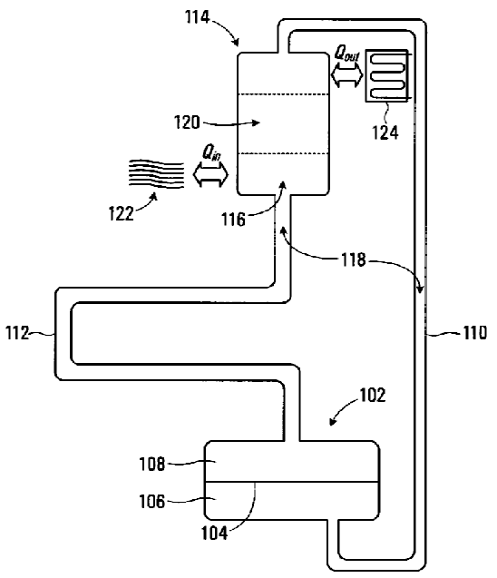
The illustration above shows a thermoacoustic transducer for converting between thermal energy and mechanical energy.
Thermo-acoustic heat engines:
- (a) Either use high-amplitude sound waves to pump heat, e.g. refrigeration machines under F25B 9/145, or
- (b) Use a heat difference to produce work in the form of sound waves, which for example are converted to electric power using a transducer.
Engines of type (b) are to be classified here.
Examples of places in relation to which this place is residual:
Refrigeration machines using waves |
This place covers:
Illustrative example of subject matter classified:

The figure above illustrates a device that generates an oriented flux of gas molecules and utilises said oriented flux for obtaining electric energy. The device comprises a housing (2) containing gas, a membrane (3) dividing the housing into compartments, wherein the membrane (3) is provided with a plurality of funnel-like through holes (6), a bypass (7) that links the said compartments, a turbine machine (8) with an electric current generator (9), arranged within the bypass (7), and a heat exchanger (10) supplying heat to the first compartment (4). Owing to the configuration of the holes in the membrane, the number of molecules that penetrate from the first compartment (4) to the last compartment (5) exceeds the number of molecules that return from the last compartment (5) to the first compartment (4). Due to the difference in pressures in the compartments, the gas flux flows through the bypass (7) and generates electricity by means of turbine machine (8) and the generator.
In this place, the following terms or expressions are used with the meaning indicated:
Thermophoresis or Thermodiffusion | Different particles in a mixture of mobile particles exhibit different responses to the force of a temperature gradient. |
This place covers:
Thermo-magnetic motors make use of the reduction of a magnetic force under thermal influence (Curie effect).
Illustrative example of subject matter classified in this group:
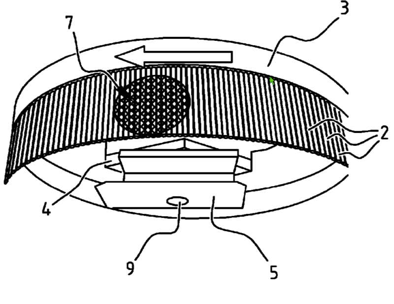
The illustration above shows a thermodynamic device based on a magnetic field and curie effect.
Attention is drawn to the following places, which may be of interest for search:
Electric motors using thermal effect |
This place covers:
Illustrative example of subject matter classified in this group:
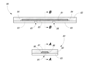
An actuation apparatus includes at least one magnetic shape memory (MSM) element containing a material configured to expand and/or contract in response to exposure to a magnetic field. Among other things, the MSM element may be configured to pump fluid through a micropump by expanding and/or contracting in response to the magnetic field. The magnetic field may rotate about an axis of rotation and exhibit a distribution having a component substantially perpendicular to the axis of rotation. Further, the magnetic field distribution may include at least two components substantially orthogonal to one another lying in one or more planes perpendicular to the axis of rotation. The at least one MSM element may contain nickel, manganese, and gallium. A polymerase chain reaction (PCR) may be enhanced by contacting a PCR reagent and DNA material with the MSM element.
Attention is drawn to the following places, which may be of interest for search:
Hydraulic or pneumatic fluid pressure actuators | |
Metal hydrides materials | |
Optical actuators | |
Piezoelectric actuators | |
Piezoelectric devices in general; Electrostrictive devices in general; Magnetostrictive devices in general | |
Bulk negative resistance effect devices |
Actuating elements for mechanical power producing mechanisms using expansion or contraction of bodies due to heating, cooling, moistening, drying or the like to be classified in F03G 7/061.
This place covers:
Illustrative example of subject matter classified in this group:
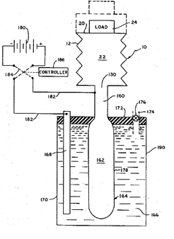
The illustrative example above shows an actuator incorporating an electrolytic gas generator-evacuator is disclosed. A membrane of material selectively permeable to a drive gas is inserted in a combined inlet-outlet of an expandable chamber. The membrane forms a portion of an electrolytic cell by being immersed in a body of electrolyte capable of transporting an ionic species of the drive gas between the membrane as one electrode and a counter electrode. By connecting the combined inlet-outlet of the chamber to the outside surface of the membrane and cyclically driving the electrolytic cell in a drive gas generation mode and a drive gas evacuation mode, the chamber will cyclically expand and contract.
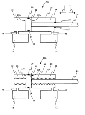
The illustrative example above shows a metal hydride actuator.
This place covers:
Illustrative example of subject matter classified in this group:
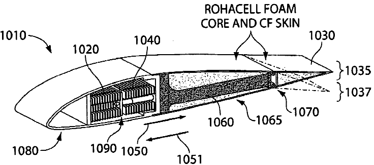
Illustrated is a device involving electrochemical actuation. The devices may comprise at least one component capable of exhibiting a volumetric or dimensional change upon application of a voltage. The volumetric or dimensional change may produce mechanical work. The devices may be capable of exhibiting high actuation rates and supporting high amounts of stress (e.g., in tensile and/or compressive loading). The device may provide morphing structures that may be useful in applications such as airfoils.
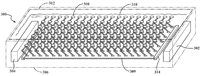
Illustrated is a protein array for converting chemical energy into mechanical energy.
This place covers:
Electroactive polymers not otherwise provided for, e.g. polymers with carbon nanotubes, ionic or responsive gels, integrated polymer metal composites (IPMC), like nafion or flemion.
Illustrative example of subject matter classified in this group:
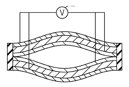
An expansion and contraction actuator has a first long actuator portion and a second long actuator portion that face each other and connection members that connect the long sides of each of the first long actuator portion and the second long actuator portion to each other, in which a part of the first long actuator portion and a part of the second long actuator portion are apart from each other to thereby form a hollow structure; the first long actuator portion and the second long actuator portion each have a pair of long electrodes and a long electrolyte layer having an electrolyte, long internal electrodes thereof are the same cathode or anode electrodes, long external electrodes thereof are counter electrodes thereto, and the actuator expands and contracts in the direction of the screw axis by voltage application.
Attention is drawn to the following places, which may be of interest for search:
Liquid crystal polymers | |
Touch screens or pads | |
Piezoelectric or electrostrictive devices |
This place covers:
Illustrative example of subject matter classified in this group:
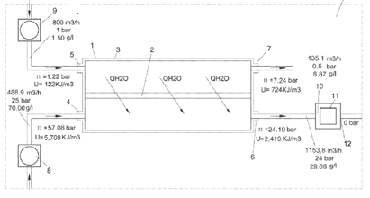
The illustrative example above is framed within the field of or depuration, such as desalination or depuration and the use of said processes to produce energy, specifically, hydroelectric energy, from the direct osmosis process used in the treatment of saline water and urban waste water.
Attention is drawn to the following places, which may be of interest for search:
Osmotic membranes | |
Desalination | |
Electrolysis of water |
This place covers:
Illustrative example of subject matter classified in this group:
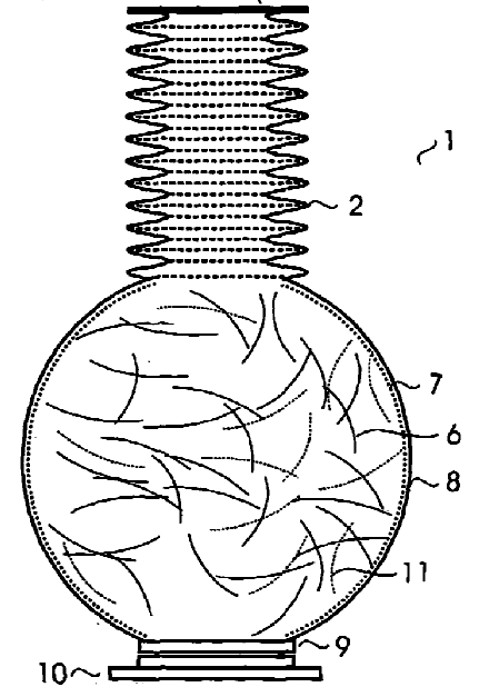
Illustrated above is an actuator (1), comprising a gas tight chamber (8) provided with expansion means (2) and having highly reflecting inner walls. The chamber (8) is filled with a gas and with carbon fibres (6). Light generating means are provided, the light of which may enter the chamber via a window (9), for heating the carbon fibres (6) and therewith the gas in the chamber (8), for generating a force and/or a movement by expanding the expansion means (2).
Attention is drawn to the following places, which may be of interest for search:
Transducers for transforming light into mechanical energy | |
Use of radiation pressure or radiometer effect | |
Photosensitive materials | |
Photoelectric discharge tubes |
This place covers:
Illustrative example of subject matter classified in this group:
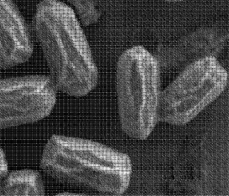
Illustrated in the figure above is a system for generating energy comprising, a hygroscopic material, a generator, a transmission coupled to the hygroscopic material and coupled to the generator to transfer energy from the hygroscopic material to the generator, whereby an application of a cycle of high relative humidity environment and low relative humidity environment to the hygroscopic material results in a change in size of the hygroscopic material and energy being transferred to the generator. The hygroscopic material can include microbial or bacterial spores.
This place covers:
Mechanical-power-producing mechanisms not otherwise provided for and characterised by a specific use, e.g. nano or micro scale applications for use in the human body.
This place covers:
Illustrative example of subject matter classified in this group:
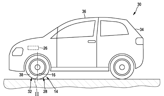
Wheel device for use as e.g. alternator, in car, has energy conversion element to convert mechanical energy into electrical energy in operating condition, where conversion element includes smart material designed as electroactive polymer.
This place covers:
Illustrative example of subject matter classified in this group:
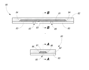
An actuation apparatus includes at least one magnetic shape memory (MSM) element containing a material configured to expand and/or contract in response to exposure to a magnetic field. Among other things, the MSM element may be configured to pump fluid through a micropump by expanding and/or contracting in response to the magnetic field. The magnetic field may rotate about an axis of rotation and exhibit a distribution having a component substantially perpendicular to the axis of rotation. Further, the magnetic field distribution may include at least two components substantially orthogonal to one another lying in one or more planes perpendicular to the axis of rotation. At least one MSM element may contain nickel, manganese, and gallium. A polymerase chain reaction (PCR) may be enhanced by contacting a PCR reagent and DNA material with the MSM element.
This place covers:
Illustrative example of subject matter classified in this group.
Control or monitoring related features of mechanical-power-producing devices not otherwise provided for.
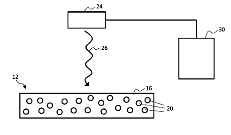
An electroactive material actuator device is provided having a controllable stiffness profile. An actuator member of the device comprises an electroactive polymer material having light absorbing filler elements embedded or contained therein. The light absorbing filler elements are adapted to absorb and convert incident light energy to heat energy to therefore heat surrounding sections of the electroactive material. By selectively controlling an intensity level or spectral composition of a light source directed at the actuator member, a specific degree and spread of heating can be achieved across the member and, as a result, a specific desired stiffness or flexibility profile realised across the body of the actuator member.
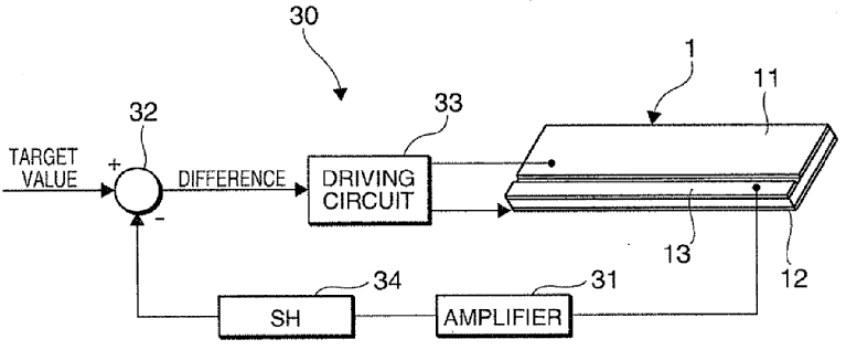
Illustrated is an actuator, and more particularly, the configuration of an actuator which can detect a direction of displacement or an amount of displacement.
This place covers:
Safety arrangements related features of mechanical-power-producing devices not otherwise provided for.
This place covers:
Illustrative example of subject matter classified in this group:
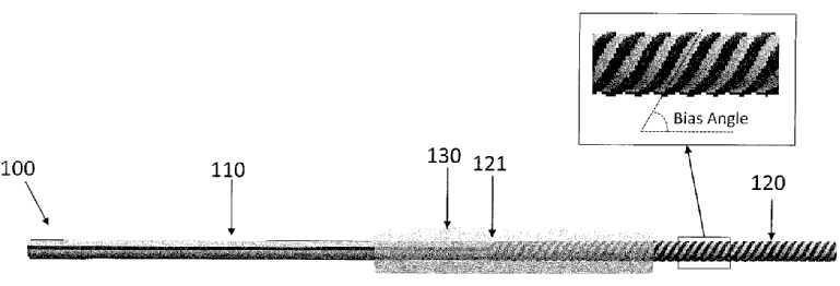
Manufacturing of artificial muscle actuators
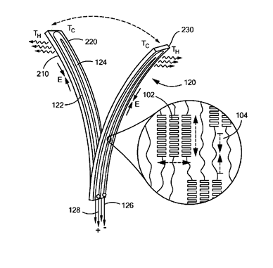
Illustrated above are bending actuators and, more particularly, to thermally activated polymer bending actuators.
This place covers:
Mechanical-power-producing mechanisms not otherwise provided for using pressure differences or thermal differences occurring in nature. Mechanisms using electrostatic charges occurring in nature (thunderbolts) also to be classified here.
Illustrative example of subject matter classified in this group:
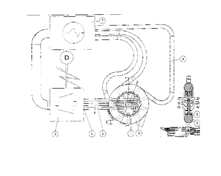
Converting ambient heat into a technical usable energy form
This place does not cover:
Using expansion or contraction of bodies due to heating, cooling, moistening, drying or the like |
This place covers:
Environmental heat plants using pressure or thermal differences occurring in nature or ocean thermal energy conversion (OTEC) plants using an Organic Rankine Cycle (ORC) or a Kalina cycle.
An Organic Rankine cycle uses an organic fluid, like CFC, HFC, HC, PFC, with a boiling point lower than the water boiling point.
In a Kalina cycle the conversion of heat into mechanical power is realized by using a solution of two fluids with different boiling points, the most widely used combination being water and ammonia.
This place covers:
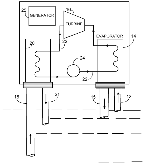
Environmental heat plants using pressure or thermal differences occurring in nature or ocean thermal energy conversion (OTEC) plants using heat pumps.
Illustrative example of subject matter classified in this group:
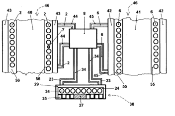
The figure above illustrates a cooling electric energy generator with Stirling engine (46) integrated in it that absorbs heat energy from environment through external heat collector (30), and it concentrates heat energy on heat side of Stirling engine (46) by internal heat pump device (8). Internal heat pump device (8) cools cold side of Stirling engine (46) as well as it absorbs heat energy from cool side and it concentrates heat energy on heat side of Stirling engine (46). Internal heat pump device (8) is initially started with electric energy from external generator. Stirling engine (46) starts rotation in electric generator (48), which further supplies internal heat pump devices (8), through programmed switcher. Heat energy from environment and from cold side of Stirling engine (46) is four to nine time higher quantity than electric energy necessary for functioning internal heat pump device (8).
This place covers:
Illustrative example of subject matter classified in this group:
Attention is drawn to the following places, which may be of interest for search:
Floating platforms adapted for special purposes | |
Tidal or wave energy | |
Large diameter hoses for OTEC plants |
This place covers:
Illustrative example of subject matter classified in this group:
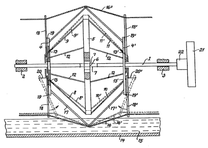
Device for generating driving force with a middle disc held in a cage-like manner by ropes between two coaxially mounted side discs, which is transferred into an unstable equilibrium position by moistening a rope under the then effective tensile force and achieves rotary motion, characterised in that the central disc (5) holding ropes (8, 9 and 10, 11) are guided as holding ropes in these side discs (4, 4 ') and are connected to lever-like tendons (18,18') mounted on these side discs, on the one hand, to which on the other side, the ropes (16, 16"), alternately subjected to moistening and drying, engage.
Systems using elasto-caloric or mechano-caloric effect, quasi the reversal of the shape memory alloy effect, should be searched and classified in F25B 23/00, not in F03G 7/06.
Attention is drawn to the following places, which may be of interest for search:
Mechanical actuators for fire prevention controlling mechanisms | |
Program-controlled manipulators, e.g. robots | |
Aircraft adjustable control surfaces | |
Aerospace actuators | |
Micromechanical actuators | |
Microelectro-mechanical systems (MEMS) | |
Actuators for locks | |
Locks with thermo-electric actuators, e.g. heated bimetals | |
Operating locks by bimetallic or memory-shape element | |
Locks with fusible element, bimetal, memory shape or swelling material | |
Using thermal expansion of non-vaporising liquids | |
Material properties, shape memory behaviour | |
Joints fasteners using shape memory alloys | |
Actuating mechanisms for brakes | |
Actuators for valves | |
Refrigeration machines, combined heating and refrigeration, heat-pump systems | |
Systems using electric or magnetic effect | |
Systems with a single mode of operation, e.g. elasto-caloric or magneto-caloric effect | |
Systems using electro-caloric effect | |
Systems using magneto-caloric effect | |
Adjusting means for optical elements | |
Imaging systems using optical elements for stabilisation of the lateral and angular position of the image | |
Power-operated focusing for cameras, projectors or printers | |
Adjustment of optical system | |
Temperature control by expanding bodies | |
Thermal operated switches for fire alarms | |
Sensitive elements capable of producing movement, bimetallic compound strips or plates | |
Thermally actuated switches, e.g. making use of shape memory material | |
Electro-thermal relays making use of shape memory material | |
Electric machines using piezoelectric effect | |
Electric motors using thermal effects | |
Thermoelectric devices using Seebeck or Peltier effect |
This place covers:
Mechanical-power-producing mechanisms or actuators, not otherwise provided for, characterised by the actuating element, e.g. thermal or humidity actuation.
Illustrative example of subject matter classified in this group:
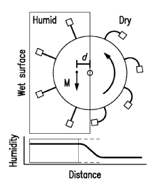
Illustrated is an evaporation-driven engine comprising a water source having a high humidity zone proximate a surface of the water source, a supporting structure and a hygroscopic material disposed on the supporting structure and configured to generate mechanical force in response to a changing relative humidity, wherein the hygroscopic material is repeatedly exposed to the high humidity zone and removed from high humidity zone thereby causing the hygroscopic material to generate mechanical force.
This place covers:
Illustrative example of subject matter classified in this group:
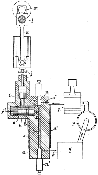
This invention relates to motors of the kind in which motion is produced by transmitting to a piston the expansion of a liquid due to the heating thereof in a temporarily closed space surrounded by a continuously heated body, said space having an inlet and outlet closable by valves, and wherein the expanded heated liquid is displaced through said outlet by the introduction of cold liquid through said inlet, the displaced liquid being led through a cooling device prior to being utilised again in the heated working space.
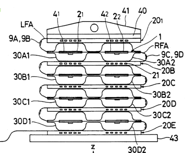
An actuator is composed of a plurality of three-dimensionally arranged containers each of which is constructed into deformable configuration and each of which is set to accommodate therein an amount of expandable fluid in response to the increase of the temperature, a heat supply device for supplying the heat to the fluid in each of the containers, a cooling device for cooling the fluid in each of the containers and a control device for controlling the heat supply device and the cooling device.
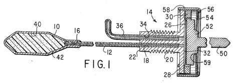
The invention relates to fluid pressure responsive devices and, in particular, to devices employing a member which is movable by a fluid pressure and volume change, such as fluid expansion and contraction in response to changes in temperature.
Attention is drawn to the following places, which may be of interest for search:
Stirling cycle type engines | |
Positive-displacement pumps pumping by heat expansion of the pumped fluid |
This place covers:
The enclosed fluid changes its phase when heated/cooled, e.g. wax actuators, liquid crystal actuators, low melting point alloy actuators, melting polymer actuators.
Illustrative example of subject matter classified in this group:
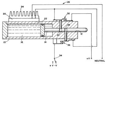
A piston (14) is slidably received in a chamber (10). The chamber is filled with an expandable medium (16), such as wax that expands and contracts significantly as it undergoes a phase change from a solid to a liquid state. A Peltier effect chip (20) selectively adds and removes heat energy from the chamber, hence the medium, to cause the medium to change phase. A temperature control (26) maintains the temperature of the medium substantially at the phase change temperature such that the addition of heat causes an isothermal melting (hence, expansion) and the removal of heat causes an isothermal solidification (hence, contraction). The chamber defines a plurality of thin branches such that the heat is transferred more effectively.
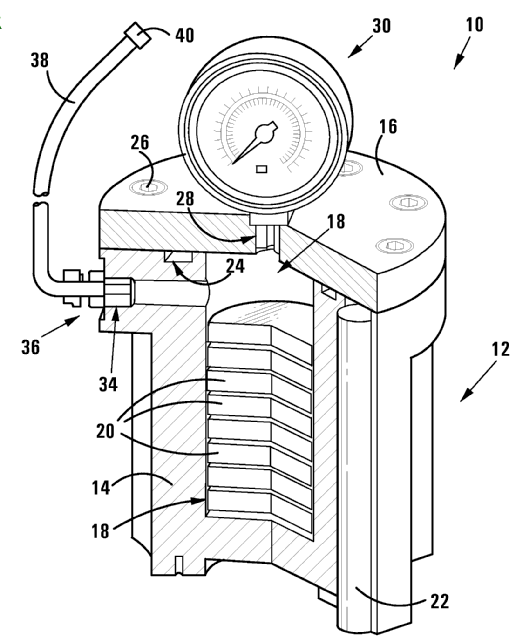
A wax actuator and a method of actuating by means of a wax actuator
Attention is drawn to the following places, which may be of interest for search:
Details of liquid crystal polymers | |
Temperature control by expanding bodies |
This place covers:
Illustrative example of subject matter classified in this group:
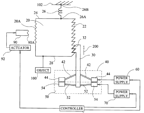
The illustration above shows a ratcheting micromotor with a ratchet bar defining ratchet teeth along an edge thereof, and first and second ends in opposition to one another. The first end is adapted to be coupled to an object to be moved. A spring is coupled on one end thereof to the second end of the ratchet bar and adapted to be fixed at another end thereof to a base. A bidirectional actuator configured for linear movement in one of a first direction and a second direction, and when energized has a common yoke coupled to a central portion thereof for movement in correspondence therewith.
The common yoke includes teeth formed along an edge and positioned such that its teeth engage a portion of the ratchet teeth. A control system energizes the bidirectional actuator to move, alternately, in the first direction and the second direction.
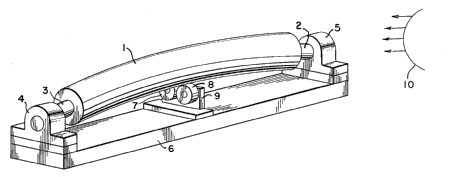
The illustration above shows a motor comprising a rotor supported to rotate freely about its longitudinal axis while the axis is confined to an elastically bowed configuration by internal or external means. Heat, cold or other stress inducing means applied to the side of the rotor causes local internal stresses that cause the rotor to rotate in the direction that allows relaxation of the induced stress.
This place covers:
Illustrative example of subject matter classified in this group:
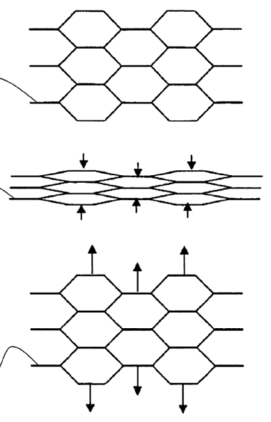
Illustrated above is a morphing cellular structure, comprising a group of unit cells with each unit cell having a cellular geometry, the group of unit cells formed of a first active material, where the first active material has a first state and a second state, and where each unit cell has a configuration where the configuration of each unit cell, while the first active material is in the first state, is different from the configuration of each unit cell while the first active material is in the second state, and where the first active material is responsive to a first actuation signal such that when the first actuation signal is actuated, the active material is deformed from the first state to the second state, thereby changing the configuration of each unit cell affected by the actuation of the first actuation signal and morphing the cellular structure, wherein the first actuation signal is a signal selected from a group consisting of a temperature change, redox reaction, pH change, electromagnetic field, chemical reaction, electric current, electric field, and magnetic field; and wherein the active material is deformable from both a first state to a second state and from a second state to a first state such that the deployment is a re-settable deployment where the active material is re-settable through an external reset signal, allowing for at least one additional deployment, the re-settable deformation being selected from a group consisting of deforming from the first state to the second state upon receiving the first actuation signal and deforming from the second state to the first state when the first actuation signal is removed, and deforming from the first state to the second state when the first actuation signal is removed and deforming from the second state to the first state when the first actuation signal is received.
This place covers:
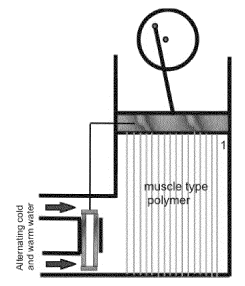
Thermally activated polymers, e.g. polymers with nanotubes, shape memory polymers.
Thermoresponsive polymers with low critical solution temperature (LCST).
Illustrative example of subject matter classified in this group:
Attention is drawn to the following places, which may be of interest for search:
Using non-thermally activated polymers |
This place covers:
Illustrative example of subject matter classified in this group:
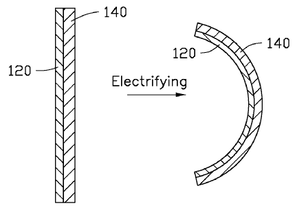
Illustrated is an electrothermal actuator comprising at least two operating portions electrically connected with each other to define at least one conductive path and at least two electrodes spaced from each other and configured to introduce a current to the at least one conductive path, wherein each of the at least two operating portions comprises a flexible polymer layer and a carbon nanotube paper stacked with each other, the carbon nanotube paper is at least partly embedded into the flexible polymer layer; a thickness ratio of the carbon nanotube paper and the flexible polymer layer is in a range from about 1:7 to about 1:10, a density of the carbon nanotube paper is greater than or equal to 0.5 g/cm3, a thermal expansion coefficient of the carbon nanotube paper is greater than or equal to ten times that of the flexible polymer layer; a conductivity of the carbon nanotube paper of each of the at least two operating portions along a current direction of the at least two operating portions is in a range from about 1000 S/m to about 6000 S/m.
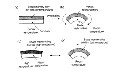
Attention is drawn to the following places, which may be of interest for search:
Temperature control by expanding bodies |
This place covers:
Illustrative example of subject matter classified in this group:
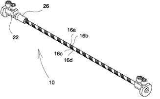
The actuator comprises a strand of shape memory material having a length that is variable between a first length corresponding to an undeformed state and a second length corresponding to a state of lengthwise deformation. The strand is arranged to return to the undeformed state when it is heated to a predetermined temperature. The strand comprises a fixed end and a mobile end arranged to move between a first and a second position when the variable length of the SMM strand changes. The actuator further comprises a heating wire coiled around the strand for heating the strand, the coiled heating wire forming a circular helix, the uniform slope of which is selected so as to avoid any substantial change of the arc length of the circular helix caused by the strand changing its length.
Attention is drawn to the following places, which may be of interest for search:
Electrically-conductive connections using shape memory materials |
This place covers:
Shape memory elements using wires.
Illustrative example of subject matter classified in this group:
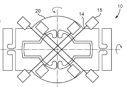
An SMA (scalable multi-element shape memory alloy) actuator is arranged to tilt the mirror in a zoom camera to effect optical image stabilization. The actuator may comprise four angled-V SMA wires. The actuator may alternatively comprise a gimbal flexure and SMA wires. In this case, there may be four SMA wires or two SMA wires and two springs. The SMA wires may be straight wires or wires hooked in a V shape.
This place covers:
Shape memory elements using springs.
Illustrative example of subject matter classified in this group:
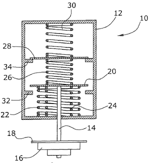
Actuators are known for operating a control element, with a control element (14) which is fastened to a force-transmitting member (20), an opening spring (26) made of a shape memory alloy which acts on the force-transmitting member (20) in a first direction, the spring force being dependent upon the temperature of the opening spring (26), and a restoring spring (22) which acts on the force-transmitting member(20) in a direction opposite to the first direction. In order to prevent unwanted opening at ambient temperatures above the structure conversion temperature, according to the invention, a closing spring (24) made of a shape memory alloy acts on the force-transmitting member (20) in a direction opposite to the first direction.
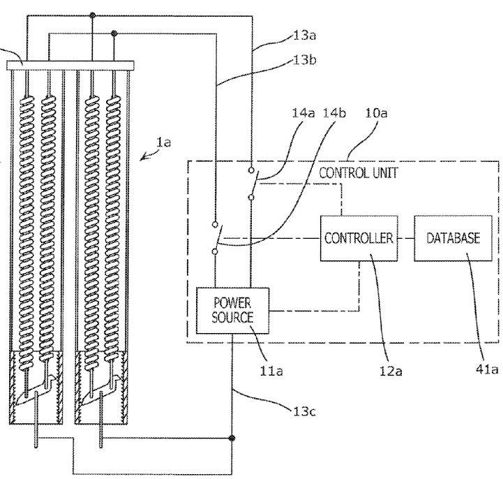
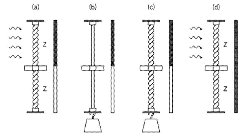
The present disclosure relates to an actuator and an actuator set that stretch or contract in accordance with a change in temperature.
This place covers:
Shape memory elements using torque tubes or torsion bars.
Illustrative example of subject matter classified in this group:
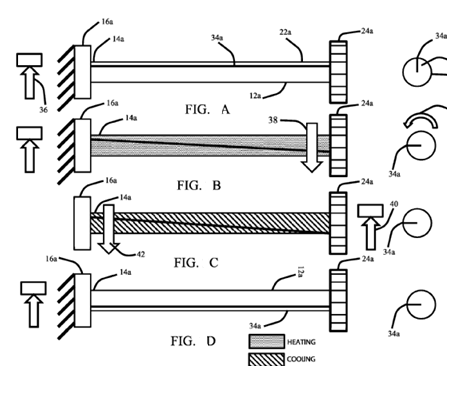
A scalable multi-element shape memory alloy (SMA) rotary motor employs a plurality of SMA tubes. A ratcheting gear transmission couples the plurality of SMA tubes in parallel to a common output. A controller provides power to a plurality of heaters associated with each of the plurality of SMA tubes, sequentially heating selected heaters to provide continuous rotational motion of the common output.
This place covers:
Shape memory elements using magnetic shape memory alloys.
Illustrative example of subject matter classified in this group:
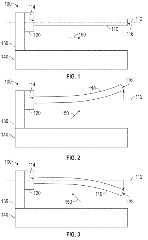
Illustrated is a method comprising:
Retaining, at an anchor, a first end of an actuation member, wherein a length of the actuation member is greater than a width of the actuation member and the length extends from the first end of the actuation member to a second end of the actuation member along a longitudinal axis when the actuation member is undeformed, and wherein the actuation member comprises a magnetic shape memory alloy; deforming the actuation member with a magnetic field to move the second end of the actuation member laterally to the longitudinal axis; and altering, at a magnetic field source, the magnetic field applied to the actuation member to alter the deformation of the actuation member.
This place covers:
Illustrative example of subject matter classified in this group:
This place does not cover:
Magnetic shape memory alloys |
Attention is drawn to the following places, which may be of interest for search:
Alloys based on nickel or cobalt and with a light metal, like titanium | |
Alloys based on nickel | |
Means for fastening cables (for SMA wires) |
This place covers:
Illustrative example of subject matter classified in this group:
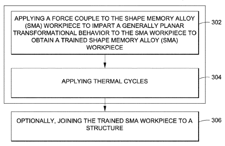
Illustrated is a method of activating a thermally actuated active material actuator defining an external surface, said method comprising the steps of:
- Producing a wireless transmission;
- Engaging a receptive element with the transmission, wherein the element is communicatively coupled to the actuator,
- Modifying the element as a result of engagement with the transmission: and
- Exposing the actuator to a heat energy activation signal or directly producing the signal, as a result of modifying the element.
This place covers:
Illustrative example of subject matter classified in this group:
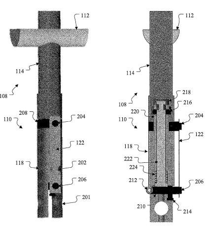
Illustrated is an apparatus comprising a latch comprising a first portion, a second portion, and a ball lock, wherein the ball lock is configured to hold the first and second portions of the latch together when the ball lock is engaged, wherein the ball lock is configured to allow the first and second portions of the latch to separate when the ball lock is disengaged and the latch further comprises a shape memory material member configured to fracture when exposed to an elevated temperature and thereby disengage the ball lock.
This place covers:
Illustrative example of subject matter classified in this group:
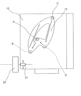
The illustration above shows a rotary actuator using shape memory alloy wires in traction.
This place covers:
Illustrative example of subject matter classified in this group:
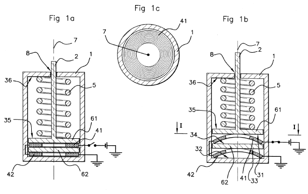
A shape memory actuator comprises a supporting body, a driven element pivotably mounted on the supporting body and in permanent contact with a driving element whose movement is determined by a SMA actuating member and by at least one resilient return member acting in opposition to the SMA actuating member, the driven element being able to take two stable positions under the action of a bistable moving system connecting the driving element to the driven element such that each toggling between said two stable positions is due to an activation of the SMA actuating member, the latter being arranged together with the bistable moving system, with the resilient return member, with the driving element and with the driven element on a same side of the supporting body in a substantially coplanar arrangement.
This place covers:
Illustrative example of subject matter classified in this group:
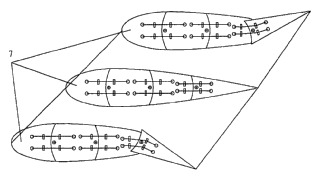
This place covers:
Illustrative example of subject matter classified in this group:
This place covers:
Mechanical-power-producing mechanisms or actuators, not otherwise provided for, using expansion or contraction bodies due to heating, cooling, drying, moistening or the like and characterised by the use, e.g. nano applications.
This place covers:
Illustrative example of subject matter classified in this group:
The illustration above shows a rotation-type actuator actuated by temperature fluctuation or temperature gradient and energy harvesting device using same.
Illustrative example of subject matter classified in this group:
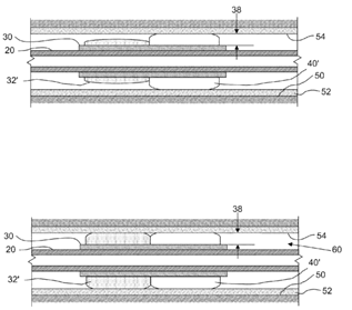
Wellbore devices for use in filtration, wellbore isolation, production control, lifecycle management and wellbore construction may include at least a first and a second shape-memory material each having an altered geometric position and each an original geometric position. Each shape-memory material may include a polyurethane material held in the altered geometric run-in position at a temperature below glass transition temperature (Tg), where the Tgs and/or the respective slope changes of the first and second polyurethane materials are different. Once the wellbore device is in place downhole and the first and second shape-memory materials are subjected to temperatures above their Tgs, the materials will deploy and expand to recovered geometric positions at or near their original geometric positions to perform their filtration, isolation, control or other function. These deployments or expansions may occur at different times or rates.
Illustrative example of subject matter classified in this group:
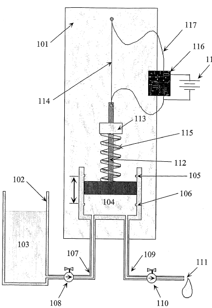
Pump useful for subcutaneous, long-term, automated drug delivery has actuator including shape memory alloy material to drive movable member from first to second position as the shape memory alloy material goes through dimensional change.
Attention is drawn to the following places, which may be of interest for search:
Pumping elements for medical purposes |
This place covers:
Control or monitoring related features of mechanical-power-producing devices or actuators not otherwise provided for and using expansion or contraction of bodies due to heating, cooling, moistening, drying or the like.
Illustrative example of subject matter classified in this group:
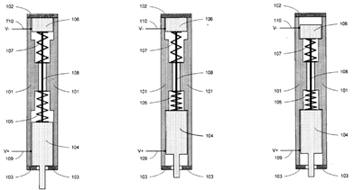
Illustrated is a pump comprising a reservoir having a maximum volume, an actuator comprising a shape memory alloy that moves a plunger, the plunger displacing liquid from the reservoir and a control system that utilizes linear feedback to sense the position of the actuator and to manipulate the actuator to provide doses of variable volumes less than the maximum volume.
The control system further comprises a microprocessor and means for position detection.
This place covers:
Illustrative example of subject matter classified in this group:
This place covers:
Safety arrangements related features of mechanical-power-producing devices or actuators not otherwise provided for and using expansion or contraction of bodies due to heating, cooling, moistening, drying or the like.
Illustrative example of subject matter classified in this group:
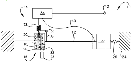
The illustrative example relates to systems for protecting actuators and the assemblies they compose from overload conditions, and more particularly, to a system for providing overload protection to same, which employs magnetorheological fluid mechanisms connected in series with or parallel to the load acting upon the actuator, so as to effect tunable protection.
This place covers:
Illustrative example of subject matter classified in this group:
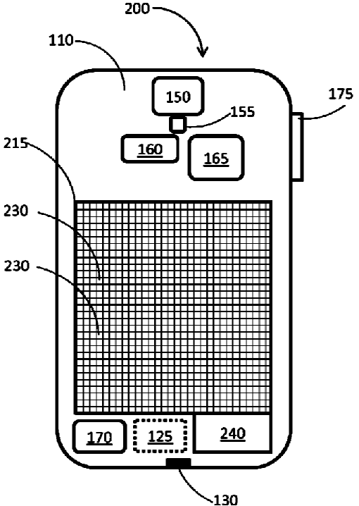
The illustration above shows a portable electronic devices requiring electrical power for their operation and specifically to those powered by harvesting kinetic energy.
Attention is drawn to the following places, which may be of interest for search:
Recovering energy from moving persons or animals | |
Brake elements for vehicles utilising wheel movement for accumulating energy | |
Devices for using the energy of the movements of the vehicles | |
Brakes storing energy during braking action | |
Speed bumps | |
Recovering energy from wave or tide energy | |
Wind motors with swinging wind-engaging parts | |
Brakes with means for making the energy available for use | |
Electric machines using piezoelectric effect, electrostriction or magnetostriction | |
Piezoelectric, electrostrictive or magnetostrictive devices in general |
This place covers:
Illustrative example of subject matter classified in this group:
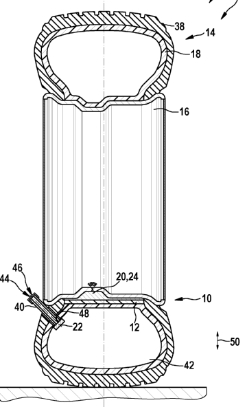
Wheel device for use as e.g. alternator, in car, has energy conversion element to convert mechanical energy into electrical energy in operating condition, where conversion element includes smart material designed as electroactive polymer.
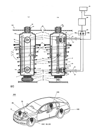
Attention is drawn to the following places, which may be of interest for search:
Making of tyres able to recover energy | |
Resilient suspensions having dampers accumulating utilisable energy, e.g. compression air | |
Vehicle auxiliary drives from oscillating movements due to vehicle running motion or suspension movement | |
Vehicle decelerating or arresting surfacings, e.g. arrester beds | |
Recovering energy from moving vehicles by aerodynamic devices, e.g. wind generators |
This place covers:
Illustrative example of subject matter classified in this group:

Illustrated is a kinetic energy collector mechanism for generating electric power from passing vehicles, using a main axle connected to a flywheel, wherein the main axle is supported on two bearings and/or rollers, said main axle having a half-cylindrical support section for the vehicle wheels, and having attached on each end at least one flywheel that is mounted so as to transmit load in only one direction while it can rotate freely in the opposite direction, said main axle rotating in an angle ranging between 0° and 120°, preferably 45°, equivalent to 1/8th of a turn as the vehicle wheels pass over the half-cylindrical section of the main axle, thus driving the attached flywheel; wherein the main axle is returned to its original resting position by means of springs, then repeating the rotational motion every time the main axle is driven by passing vehicle wheels; and wherein, the flywheel has enough driving force to rotate and drive a generator and its corresponding regulator by mechanical means that transmit the load to said generator with its corresponding regulator, which in turn generates electric power that is either delivered to a power network or charged in batteries.
This place covers:
Illustrative example of subject matter classified in this group:
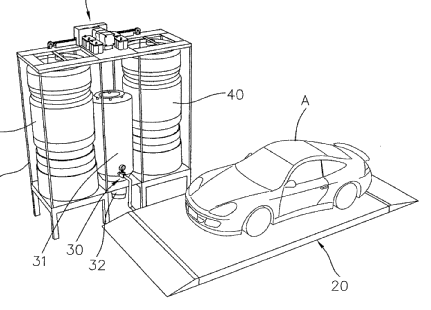
This place covers:
Illustrative example of subject matter classified in this group:
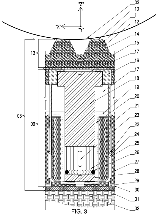
Illustrated is an apparatus to provide a means of generating electrical energy in an "environmentally clean" and efficient manner by recovering vehicular generated energy on a roadway surface comprising Modular Prefabricated Structural Sandwich Composite Panels comprised of a plurality of "spring-less" linear electromagnetic generators and a tri-axial differentially deformable composite tread comprised of crumb rubber and aggregate, an insert rod for increased "Y" axis stiffness and a foil layer to disperse heat generated by the plurality of Linear Electromagnetic Generators within the Modular Prefabricated Structural Sandwich Composite Panels.
Attention is drawn to the following places, which may be of interest for search:
Rotary generators driven by intermittent forces | |
Linear electric generators in general | |
Vibration harvesters using piezoelectric effect, electro- or magnetorestriction |
This place covers:
Illustrative example of subject matter classified in this group:
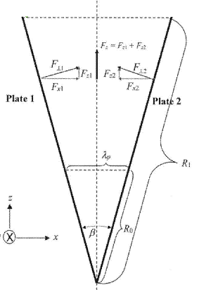
In the illustration above, a force cell provides propellant-less propulsion for linear thrust applications and fuel-less torque for rotary applications. Linear thrust applications include propulsion for aircraft, spacecraft, flying cars, construction equipment for use in low and zero gravity environments, stabilization for ultra-high buildings and realization of ultra-long unsupported spans. Rotary torque applications include engines to drive electric generators of all sizes—from mobile phone size to power station size. Force cells use radiation pressure originating from the zero-point fields in the vacuum of space—the force in the Casimir effect, to produce a macroscopic external force through use of a multiplicity of microscopic Casimir cavities consisting of wedge shaped non-charged conducting plates attached to a matrix of non-conducting material. Force cells arranged in balanced pairs can produce modulated external thrust. Force cells arranged circularly can produce modulated torque.
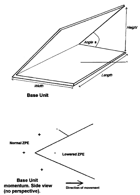
The illustration above shows two conducting plates are joined at an angle to produce a Vee or wedge shape of nanometer scale. It is claimed that this can use zero-point energy to produce a propulsive (Casimir) force or drive a machine such as a generator. The device may comprise a plurality of wedges in a zigzag shape, and may have a smooth plate ^ attached to one side, which is claimed to give rise to an asymmetric force. It is also claimed that the device, when positioned wholly or partly surrounding an object, can reduce the mass of the object.
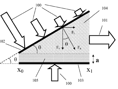
The illustration above shows methods, microstructures and devices for generating a transverse Casimir force by using an array of non-parallel conducting plates and an intervening dielectric or semiconductor material to provide propulsion in manned or unmanned space vehicles.
Attention is drawn to the following places, which may be of interest for search:
Unconventional spacecraft propulsion systems | |
Producing a reactive propulsive thrust not otherwise provided for | |
Generators or motors not provided for elsewhere |
This place covers:
Mechanical perpetua mobilia.
Examples of places in relation to which this place is residual:
Perpetua mobilia of closed loop liquid circulation | |
Perpetua mobilia of buoyancy principle | |
Dynamo-electric perpetua mobilia | |
Magnetic perpetua mobilia |
This place covers:
Illustrative example of subject matter classified in this group:
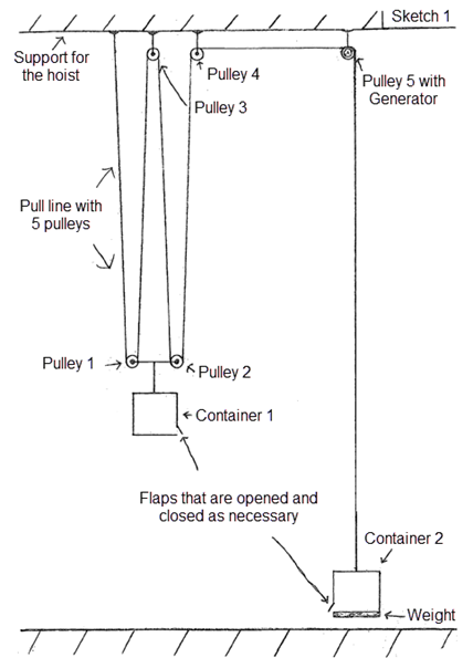
Device for producing renewable energy by pulley forces with guide rollers has reservoir and force of gravity for obtaining energy, where block and reservoir are suspended from pulley.
This place covers:
Illustrative example of subject matter classified in this group:
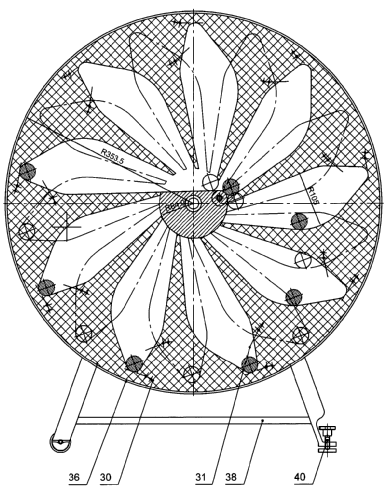
An out-of-balance drive has multiple rollers running on a common axis and multiple balls running through an effective short path via a bridge path, where balls are push-started by a starting spring.
This place covers:
Illustrative example of subject matter classified in this group:
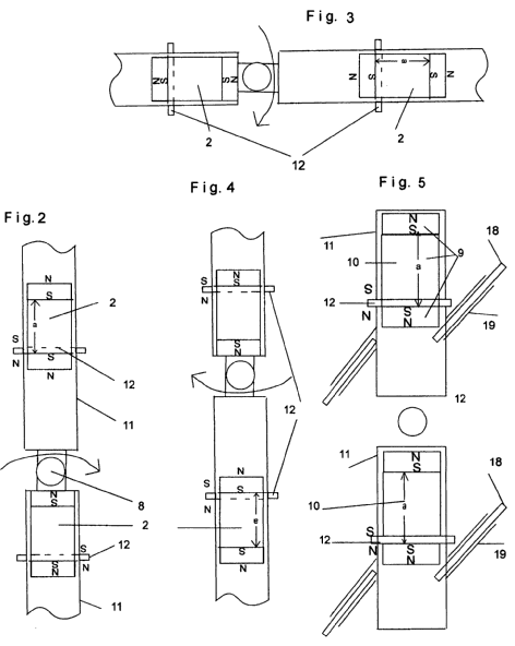
Attention is drawn to the following places, which may be of interest for search:
Magnets |
This place covers:
Illustrative example of subject matter classified in this group:
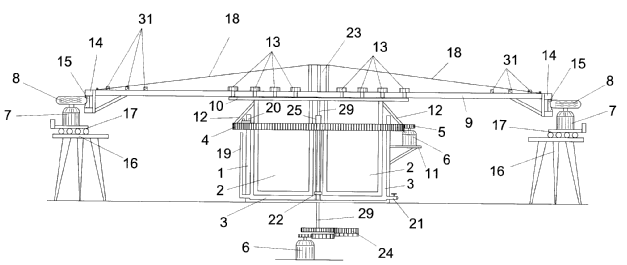
The illustration above shows an electrical generator for generating electrical energy from the kinetic energy associated with a rotating body, designed in the form of a heavy wheel. The generator includes a vertical cylindrical container housing a rotor float supported by a central attachment and a quantity of liquid in the space between the container and the rotor float. The rotor float includes a cover from which bars made from metal or another heavy metal extend, the ends of which bars support a circular ring bearing a non-slip band acted on by electric propulsion motors. In addition, a drive device, such as a ring gear, is associated with the cover and a toothed wheel is meshed therewith, said toothed wheel being associated with the rotation axle of an electrical generator.

Illustrated above is an apparatus for producing energy comprising a flywheel assembly arranged for rotation, drive means operatively coupled to the flywheel assembly, the drive means including biasing means connected to an actuator arranged to bias the biasing means providing stored energy in the biasing means, transmission means coupled between the flywheel assembly and the biasing means where release of the stored energy in the basing means provides a driving force which drives the transmission means to effect rotation of the flywheel assembly which gains momentum, extraction means operatively coupled to the flywheel assembly for rapid extraction of the momentum of the flywheel assembly as well as an energy generator associated with the extraction means for generating energy from the rapidly extracted momentum of the flywheel assembly.
This place covers:
Illustrative example of subject matter classified in this group:
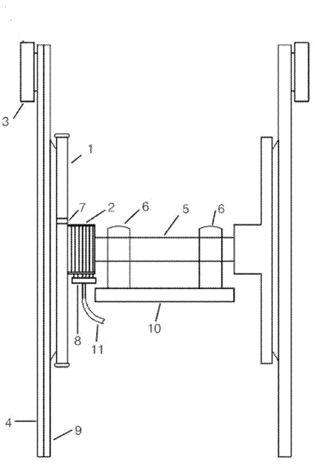
Illustrated is a torque multiplier device applicable in any machine for achieving a higher torque and for longer than currently known. For this purpose, it employs discs or plates whose diameters vary according to the number of revolutions per minutes required.
This place covers:
Illustrative example of subject matter classified in this group:
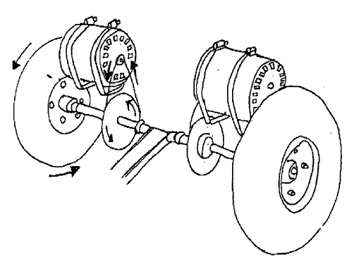
This method covers the utilization of alternators for recharging batteries and electric car mileage range improvement. It involves the usage of the rotors to charge and to extend range for an electric car, while the car is in motion. There are two methods that will be explained; these methods are called the Jent methods. The first method will be connecting the alternator to the rear axles. The second method is having an alternator rotor hybrid so that the car can still charge and have the ability to stop and apply brakes with full function.
Attention is drawn to the following places, which may be of interest for search:
Closed energy loop of the electric type |
This place covers:
Illustrative example of subject matter classified in this group:
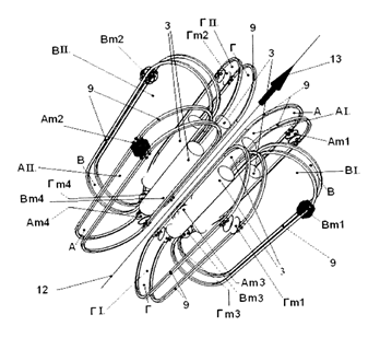
Propulsion mechanism of the dual-inertial-impulse
Attention is drawn to the following places, which may be of interest for search:
Use of propulsion power plant | |
Cosmonautic vehicles using inertia or gyro effect | |
Unconventional spacecraft propulsion systems | |
Jet propulsion plants not otherwise provided for | |
Gyroscopes in general |
This place covers:
Illustrative example of subject matter classified in this group:
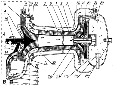
Method for converting low-grade energy and a fuelless jet engine for carrying out said method
This place covers:
Illustrative example of subject matter classified in this group:
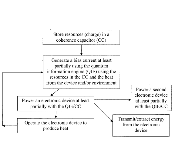
System for quantum energy storage can include a quantum information engine including topological insulator having at least one edge. A coherence capacitor can include nuclei of atoms within the topological insulator, and each nucleus can have a spin direction. An energy source can be electrically connected to the topological insulator and configured to supply a current along at least one edge of the topological insulator. The current can interact with at least one nucleus of the nuclei to flip a spin direction of the at least one nucleus.