CPC Definition - Subclass F28D
This place covers:
Heat exchangers having heat exchange media separated by a solid wall; Apparatus with heat accumulating medium.
This place does not cover:
Heated or cooled garments | |
Heat exchanger for medical treatment | |
Evaporators for separation | |
Absorbing units for separation | |
Apparatus for drying gases or vapours | |
Chemical reactors | |
Methods for manufacturing heat exchangers | |
Method for casting heat exchangers | |
Methods for brazing heat exchangers | |
Making heat exchangers by operations not covered by a single other subclass | |
Tempering units for temperature control of moulds | |
Heating, cooling or ventilating system of vehicles | |
Cooling of propulsion units | |
Radiator arrangements for aircrafts | |
Heat exchanger for aerosol containers | |
Reformers | |
Cooling cracked gas | |
Production of syngas | |
Thermal treatment for vintage | |
Lubricant cooling systems | |
Exhaust gas cooling systems | |
Exhaust gas heat recovery systems | |
Arrangements of liquid to air heat exchangers in engine cooling systems | |
Recuperators for gas turbines | |
Recycling of exhaust gas with cooler in recirculation duct (EGR) | |
Thermal treatment of combustion air, fuel, fuel-air mixtures | |
Cooling or heating regulation fluid | |
Steam generation | |
Combustion apparatus | |
Stoves or ranges | |
Domestic or space-heating systems | |
Air conditioning | |
Energy recovering systems with heat exchange between supplied and exhausted air | |
Fluid heaters having heat generating means and heat transferring means | |
Refrigeration or cooling systems | |
Evaporators for refrigerant | |
Cold exchangers for separating the constituents of gaseous mixtures involving the use of liquefaction or solidification | |
Drying | |
Furnaces; Kilns; Ovens; Retorts | |
Cooling computers | |
Nuclear reactors | |
Cooling transformers | |
Heat exchangers for fuel cells | |
Heating or cooling of secondary cells | |
Cooling solid state lasers | |
Ohmic resistance heating | |
Cooling electric apparatus | |
Cooling LEDs | |
Heat exchanging means at junction of thermoelectric devices | |
Cooling semiconductors | |
Cooling facilitated by shape of device | |
Cooling by air | |
Cooling by liquid | |
Cooling by change of state |
This place covers:
Radiator-type heat exchangers, e.g. with plate-like conduits or tubular conduits, e.g. for domestic heating (a heating medium flows inside the heat exchanger, for heating the outside air) or for engine cooling systems (a hot fluid flows inside the heat exchanger and is cooled by the outside air) ; Tanks with integrated heat exchange conduits.
F28D 1/02 relates to heat exchangers with conduits immersed in a large body of fluid,
e.g. heat exchangers immersed in a natural body of water
Example:
US 5931217 A :
Marine heat exchanger with low profile header construction
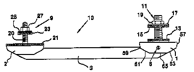
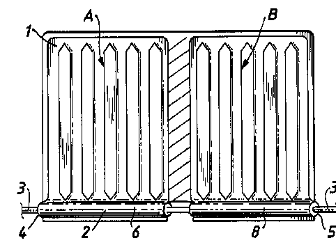
e.g. thermosiphon radiators
Example:
US 6009935 A:
Thermosyphon radiator comprising a sealed panel (1) formed into two discrete chambers A,B, each containing a reservoir of vaporising liquid (6) and a heating member (3).
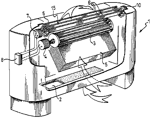
e.g. convectors having air flow channels, with an air driving element
Example: US 6120372 A
Fan convector (1) with adjustable air deflector elements (6) for space heating - uses thermostat (8) to control operation of fan (3) and deflectors (6) in air outlet to control temperature
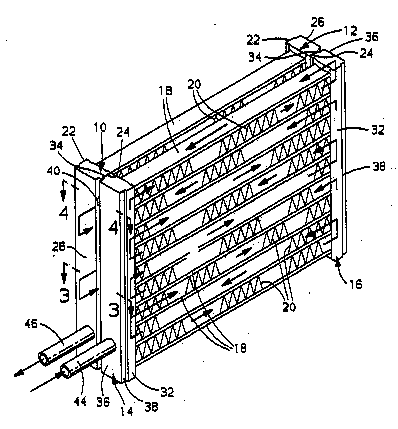
F28D 1/03 relates to heat exchangers with plate-like or laminated conduits
e.g having conduits formed by paired plates touching each other
Example:
US2011079378 A
Fluid/air heat exchanger, e.g. air cooled oil cooler comprising a first sheet metal plate (2) folded with tight folds to form fins (3) and placed over a second sheet metal plate (6) in order to form channels (4) for the passage of the fluid. 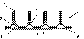
F28D 1/04 relates to heat exchangers with tubular conduits
e.g with bent conduits
Example:
US 4901791 A
Refrigeration fluid condenser assembly - has parallel flow passages (A, B) defining serpentine fluid paths with unequal length passages
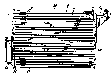
e.g. with straight conduits
Example:
US 5348081 A
Condenser for automotive air conditioning system, comprising, a first and second condenser module including two parallel tanks, (10,12, 14,16) interconnected by a plurality of extruded aluminum tubes (18) with fins (20)
F28D 1/06 relates to heat exchangers with conduits forming part or being attached to the tank containing the body of fluid
Example:
US5722487 A
Channelling members (6) on the outside surfaces of the ends of a large tank (2) for carrying heat transfer fluids and controlling the temperature of the tank contents, the channel member having straight sections (8) arranged in a spiral pattern and joined together by arcuately shaped fillets (10)
This place does not cover:
Evaporative cooler |
Attention is drawn to the following places, which may be of interest for search:
In this place, the following terms or expressions are used with the meaning indicated:
Large body of fluid | either an unlimited body of heat-exchange medium, e.g. ambient air, surrounding the stationary conduits assemblies for the first heat-exchange medium, also with conduits for the large body of fluid and circulation by means of a fluid-driving element, or a limited amount of heat-exchange medium, e.g. water, in a container, without mass-transfer with the outside during the heat transfer process |
This place covers:
Trickle coolers with indirect contact; Falling film heat exchangers; Distributing arrangements.
Example:
US 5709264 A
Falling film heat exchanger comprising a number of vertically oriented, spaced apart passage walls (10) defining a number of alternating first and second passages (12,14), with slotted dividing bars (54) located between the passage walls (10) defining the second passages (14). The slotted dividing bars (43) have spaced, vertically oriented slots (58) to cause the liquid to flow against the passage walls defining the second passages (14), thereby to enhance formation of liquid film on the passage walls (10). The
This place does not cover:
Evaporative cooler |
Attention is drawn to the following places, which may be of interest for search:
Film evaporators for separation | |
Chemical reactors of thin film type |
This place covers:
Indirect evaporative coolers.
Example:
US4976113 A
Indirect evaporating gas cooling system consists of a casing (1) with an inlet (2) for gas flow, outlets (3, 4) for main flow and an auxiliary flow travelling in the opposite direction to the main one. The casing contains moist channels (7) of a wetted capillary-porous material, and dry channels (8) of a water-impermeable material, joining at the outlet (3) end, and also a liquid feed system to moisten the capilary-porous material. The total gas stream gets cooled down to the dew point without changing its moisture content, while the auxiliary stream gets heated (due to heat withdrawal from the main gas stream) and humidified (due to evaporation of moisture from the wettable capillary-porous solid 6 thereinto).
This place covers:
- heat exchangers with conduits for one medium being in heat conductive contact with conduits for the other medium;
Example:
US 7438123 B
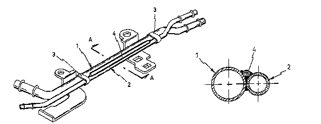
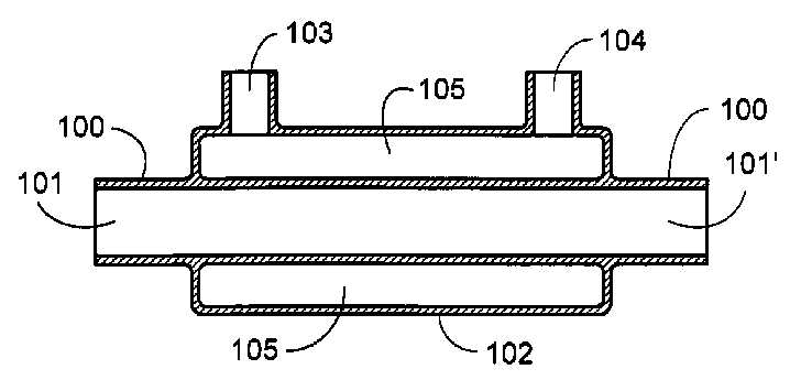
Blow-by gas pipe (1) is a pipe linking an engine crankcase and the downstream section of a carburetor; water cooling pipe (2) is a pipe linking an engine cooling passage outlet and a water pump; the pipes (1, 2) are attached to each other and a filled-in solid bar (4) is attached between pipes (1,2).The pipe-type heat exchange device is manufactured by brazing within a furnace.
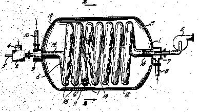
- tube and shell heat exchangers (the shell or casing is considered as a stationary conduit for one heat exchange medium): with helically coiled tubes; with spirally coiled tubes; with tubes having a single U-bend; with serpentine or zig-zag bent tubes; with conduits arranged one within the other (tube-in-tube heat exchangers); with return type tubes, with conduits arranged in parallel spaced relation (tube bundles).
Heat exchangers with helically coiled conduits are classified in F28D 7/02
e.g. having a cylindrical configuration:
Example:
US 4371036 A
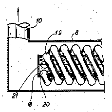
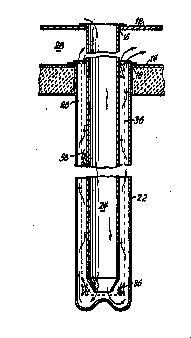
Heat exchanger functioning as an evaporator, used in a water/water heat pump, having a mantle-pipe (8) which is part of a closed water circuit which is placed in the ground in order to pick up heat from the ground. In the mantle-pipe (8) a centrally placed core pipe is part of the secondary circuit. Around this core pipe three parallel copper pipes (19, 20, 21) are coiled in helical shape.
Heat exchangers with spirally coiled conduits are classified in F28D 7/04:
Example:
US 6607027 B
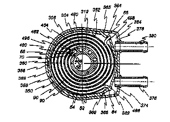
Heat exchanger usable as an oil cooler including an inlet (378) and an outlet (380) for flow of the first fluid, a pair of juxtaposed tube segments (52, 54) coiled about the central axis (56) to form a plurality of alternating concentric coils, wherein the tube segments have flattened cross sections and wherein the tube segments are spiraled about the central axis.
Heat exchangers with conduits having a single U-bend are classified in F28D 7/06:
Example:
US 2011132586 A
The heat exchanger (1), particularly exhaust gas heat exchanger comprises a tube bundle (15) fixed to a cover (4) and arranged in a jacket (5). The tube bundle includes a plurality of tubes (6) having a generally U-shaped bend region disposed between at least two straight tube ends, wherein at least a portion of the at least two straight tube ends includes flat tubes
Heat exchangers with conduits being otherwise bent, e.g. in a serpentine are classified in F28D 7/08:
Example:
US 2001039329 A
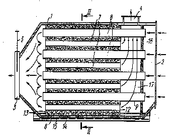
A polymer devolatilization preheater comprises an elongated, upright hollow vessel (12) defining a heating chamber (14). Heating tube bundles (26, 28, 30) are mounted in the chamber. Each bundle has elongated serpentine heating tubes arranged in configuration having a major axis that extends across the chamber in a direction transverse to the longitudinal axis of the vessel. Each tube (32, 34) includes curved tube portions and linking tube portions that interconnect the curved tube portions.
l
Heat exchangers with conduits being arranged one within the other (tube-in-tube heat exchangers), e.g. concentrically are classified in F28D 7/10:
Example:
US 2010018673 A
Thermal energy transfer device with thermal energy transfer fluid in underground water pipe (103) buried under earth layers, includes an integral structure by casting or welding.
Tube-in-tube heat exchangers with the surrounding tube being closed at one end, e.g. return type, are classified in F28D 7/12
Example:
US 4479534 A
A concentric tube type recuperative heat exchanger that includes an outer transparent tube (22) and an inner metallic tube (24) connected to headers (12,14)
Tube-in-tube heat exchangers with both tubes being bent are classified in F28D 7/14:
Example:
US 3976129 A
A composite tube composed of an inner tube (1) extending through and spaced from an outer tube (6) by radial partition walls is coiled helically. The helical composite tube coil is housed in a tank (12) having an interior silvered reflective surface and evacuated to minimize heat loss through the tank wall.
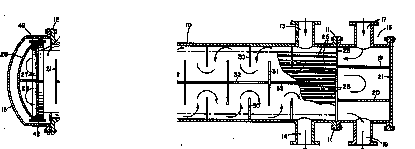
Heat exchangers with conduits being arranged in parallel spaced relation are classified in F28D 7/16:
Example:
US 4197907 A 1
Multiple pass shell-and-tube unit in which the tube-side fluid makes four passes through the unit and the shell-side fluid makes two passes, including an elongated cylindrical outer shell (10) having an external flange (11) at one end, a head (16) containing a tube-side fluid inlet (17) and a tube-side fluid outlet (18) located at the other end of the shell adjacent flange (11). Head (16) contains internal baffles (19, 20). The tube bundle in the exchanger comprises a plurality of elongated heat exchanger tubes (25) extending between a stationary tube sheet (26) and a floating tube sheet (27).
This place does not cover:
Blocks traversed by passages |
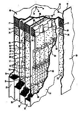
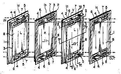
This place covers:
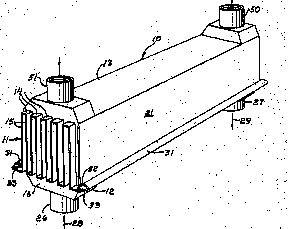
- heat exchangers of the type having superposition or juxtaposition of plate-like elements, e.g. paired plates touching each other or conduits formed by bent plates or spaced plates with inserted elements or single plate-like element, forming passageways for both heat-exchange media; the heat exchange media are distributed either by header arrangements or by openings formed in the plates for circulation from one conduit to another.
- heat-exchangers of the type having a core made by superposition or juxtaposition of plate-like elements, the core being enclosed within a casing, e.g. pressure vessel;
- multi-circuit heat exchangers, e.g. integrating different plate-like heat-exchange sections in same unit, or plate-like heat-exchange unit for more than two fluids;
- heat exchangers of the type having spirally-wound plates or laminates.
Examples:
US 3734177 A
Heat exchanger (10) exchanging heat between a first fluid which may be engine lubricating oil and a second fluid which may be a liquid coolant such as water, comprising a baffle sheet (11) of heat conducting metal arranged in serpentine section separating the first fluid that is confined by a first casing (12) from the second fluid that is confined by a second casing (13), the baffle sheet (11) having spaced folds (14) .
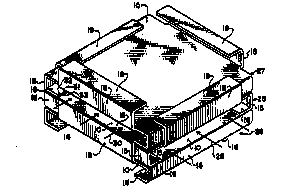
US 4848450 A
Heat exchanger including a core structure formed by a plurality of square or rectangular plate members (10) in stacked arrangement, each plate member (10) including along two opposed sides a portion (18) bent at right angles to the basic plate and then bent inwardly (19) to wrap around the next adjacent plate member (10).
US 5222551 A
A laminate-type heat exchanger having a plurality of plates (1) brazed to each other, each plate having a flange (2) and projection formed along the circumference thereof, raised portions (4) and hollowed portions (5) formed at both ends of an area surrounded by the projection and which define together reservoirs, communication holes (6, 7) formed through the raised portions (4) and the hollowed portions (5).
US 2007107889 A
Heat exchanger assembly including a core assembly (12) having passages that are closed off on at least one side by a closure bar (36). A reinforcing bar (40) is received within a channel of the closure bar to create an interface with substantially no gaps that may accumulate moisture within the core assembly.
Heat exchangers having conduits formed by spirally-wound plates are classified in F28D 9/04
Example:
US 2006124286 A
Heat exchanger having spiral shaped primary and secondary paths (10,12) separated by partition wall (14), inbetween end plates (16, 18) having individual inlet ports (22,30) and outlet ports (26,34) for respective paths
This place does not cover:
Elements constructed for building-up into stacks, e.g. capable of being taken apart for cleaning | |
Elements constructed in the shape of a hollow panel, e.g. with channels | |
Hollow panels formed by separating portions of a pair of joined sheets to form channels, e.g. by inflation |
Attention is drawn to the following places, which may be of interest for search:
Radiator type heat exchangers with plate-like of laminated conduits |
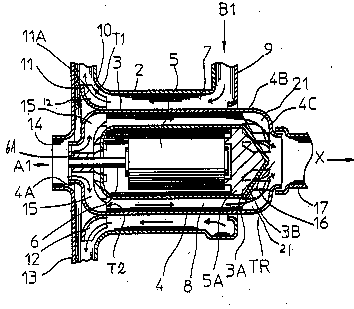
This place covers:
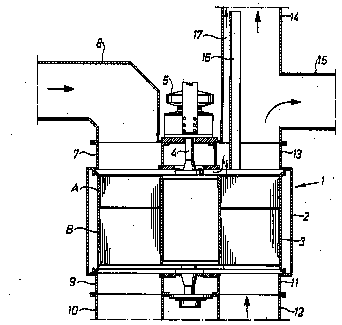
Heat exchangers with movable conduits, e.g. by rotary or reciprocating movement. The heat exchanger can move as a whole, e.g. rotary drum or roller.
Heat exchangers with moving conduits, the movement being rotary, are classified in F28D 11/02
Example:
US 5295533 A
A heat exchanger for exchanging heat between a first fluid and a second fluid comprises a moving partition member (4) for heat transmission between the first fluid and the second fluid, a housing partitioned by the moving partition member into a first chamber (7) for passing the first fluid and a second chamber (8) for passing the second fluid, and a power source for rotating the moving partition member.
Heat exchangers with rotating tubes are classified in F28D 11/04
Example:
US4596286 A
Rotary processor (10) including a shaft (12) supported by a housing (14). Mounted to the shaft (12) are a plurality of hollow helical coils (18). A fluid flow path is established serially among a reservoir (22), an inlet conduit (24), the interior of the shaft (12), the coils (18), back through the shaft to an outlet conduit (26) and to the reservoir (22). The reservoir 22 preferably includes a pump and heat exchange means to cool or heat the circulated fluid. The housing 14 has an inlet 28 and an outlet 30. Upon rotation of the shaft (12) a fluid medium in the housing (14) is conveyed from the volume at the inlet (28) toward the volume at the outlet (30).
Attention is drawn to the following places, which may be of interest for search:
Elements specially adapted for movement |
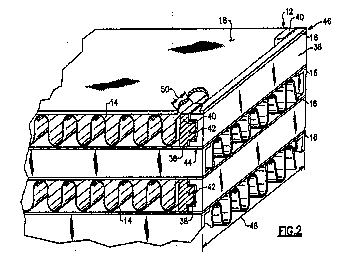
This place covers:
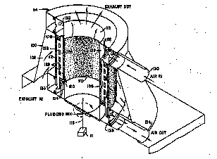
Indirect contact fluidised bed heat exchangers, e.g. with one heat-exchange medium flowing through conduits, the conduits being in contact with particles which are fluidised by another medium. The bed can be a circulating bed.
Example:
US 4313301 A
Rotating fluidized bed heat exchanger (54) particularly for recuperator section of gas turbine engines comprising an annular fluidized bed (114), defined by inner and outer spaced apart coaxial cylindrical, perforated walls (106, 108), which rotates about the longitudinal axis of the cylinders. The bed is comprised of pulverulent inert particulate material and includes fluid-containing heat exchange tubes (120) passing substantially longitudinally therethrough. Hot gases, such as turbine exhaust gases, enter the bed through the outer perforated wall, heat and fluidize the bed particles, heat the fluid, usually compressed air, in the tubes, and exit the bed through the inner perforated wall.
This place does not cover:
Fluidised bed reactors | |
Fluidised bed boilers | |
Fluidised bed combustors | |
Fluidised bed dryers |
This place covers:
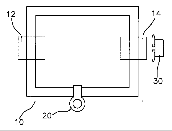
Heat exchange apparatus employing intermediate heat-transfer medium or bodies ("closed tubes" means either a sealed container or a closed loop, containing a heat exchange medium; the feature "passing into or through the conduit walls" is disregarded).
Example:
US 2008196858 A
Heat exchanger for removing heat from coolant of refrigeration system, has pump (20) connected to an enclosed pipe (10) which includes a heat absorbing section (12) and a heat dispersing section (14). A fan (30) is located close to the dispersing section. The dispersing section has a set of curved sections, where a set of fins are connected to the dispersing section.
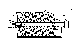
Heat pipes (the intermediate medium evaporates and condenses inside the sealed enclosure) The heat pipes can have a particular shape, e.g. flat tubes. the heat pipes can be formed as a loop, e.g. with separate evaporating and condensing chambers connected by conduits.
Heat pipes are classified in F28D 15/02
Example:
US 6026889 A
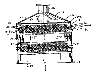
Single shell boiler (10) including a closed vessel (12) for containing a liquid heat transfer medium (14). A first bundle (20) of heat source tubes is located in the closed vessel and is adapted to be submerged within the liquid heat transfer medium for heating and vaporizing the liquid heat transfer medium. A second bundle (30) of tubes is located in the closed vessel in a position which is adapted to be above the level of the liquid heat transfer medium within the vessel to receive heat by condensation of vaporized heat transfer medium on the second bundle of tubes. A condensate distribution plate (40) is positioned between the first and second bundles of tubes. The condensate distribution plate is adapted to approximately evenly distribute condensate droplets released by the second bundle of tubes to break-up froth on the surface of the liquid heat transfer medium to enhance vapor release from the liquid heat transfer medium.
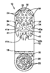
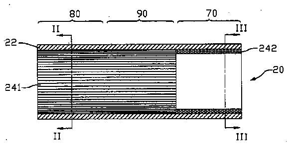
Heat pipes with capillary structures, e.g. with particular material or construction of capillary structures (wicks), or capillary pumped heat pipes.
Heat pipes having a capillary structure are classified in F28D 15/04
Example:
US 2006207750 A
A heat pipe ( 20 ) includes a metal casing ( 22 ) having an evaporating section ( 70 ) and a condensing section ( 80 ). A first type of capillary wick ( 241 ) is provided in the evaporating section and a second type of capillary wick ( 242 ) is provided in the condensing section
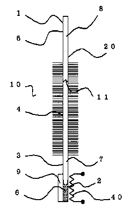
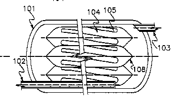
Heat pipes control means (e.g. variable conductance heat pipe).
Control arrangements for heat pipes are classified in F28D 15/06
Example:
US 2010051254 A1
Variable conductance heat pipe has a sealed container (1) including a heat receiving portion (2) for receiving an element (9) i.e. semi-conductor laser device, to be cooled. A cooler cools a heat radiating portion (4) of the sealed container. A heater (40) supplies a specific amount of heat to the heat receiving portion of the sealed container, where the heater and cooler cooperatively perform an output control operation.
This place does not cover:
Thermosiphon radiators | |
Regenerative heat exchangers | |
Refrigeration cycles with closed loops comprising evaporator and condenser |
Attention is drawn to the following places, which may be of interest for search:
Moulds with heat transfer elements, e.g. heat pipes | |
Cosmonautic vehicles using heat pipes | |
Glass melting furnaces with heat pipes | |
Apparatus for thermally treating air/fuel using heat pipes | |
Heat recovery in steam generators, using heat pipes | |
Solar collectors having heat pipes | |
Geothermal systems using heat pipes | |
Heating arrangement for dryers, using heat pipes | |
Thermal coupling by using conductive materials | |
Porous coatings | |
Intermediate heat exchange materials | |
Cooling nuclear reactors by using heat pipes | |
Cooling X-ray tubes by using heat pipes | |
Heating or cooling secondary cells with heat pipes | |
Cooling dynamoelectric machines with evaporation within casing | |
Cooling electrical apparatus using heat pipes | |
Cooling semiconductors using heat pipes |
This place covers:
Static Regenerators: a static body is first contacted by one heat exchange medium, e.g. hot gas, thereby accumulating heat, then is contacted by another heat exchange medium, e.g. fluid to be preheated, thereby transferring heat. Typical static regenerator: Rothemühle.
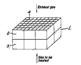
The subgroup F28D 17/02 covers regenerators using rigid bodies, e.g. granular particles, checker bricks, honeycomb body.
Example:
Honeycomb regenerator for recovering a waste heat in an exhaust gas by passing an exhaust gas and a gas to be heated alternately through the regenerator (1). Regenerator (1) is constructed by stacking honeycomb structural bodies (2, 3) made of ceramics having a main crystal phase of cordierite.
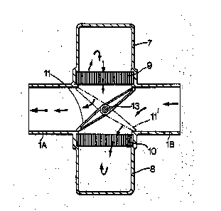
The subgroup F28D 17/04 covers distributing arrangements, e.g. valves.
Example:
US 3978912 A
Regenerative heat exchanger for gas turbine having a stationary heat-storing matrix (9, 10) in each of the flow-paths for the fluids between which heat exchange is to take place and at least one valve member (11) defining a common wall between the flow-paths and movable between two extreme operable positions,
This place does not cover:
Regenerators for Stirling engines | |
Arrangement of regenerators for preheating combustion air | |
Arrangement of regenerators for hearth-type furnaces |
Attention is drawn to the following places, which may be of interest for search:
Bricks shaped for use in regenerators |
This place covers:
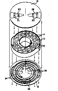
Moving regenerators: a body is moved to contact first one heat exchange medium, e.g. hot gas, thereby accumulating heat, then to contacted the oher heat exchange medium, e.g. fluid to be preheated, thereby transferring heat. Typical moving regenerator: Ljüngström.
Regenerators using movable granular particles.
Regenerators using movable rigid bodies, e.g. rotors, are classified in F28D 19/04. The flow through movable carrier can be e.g. radial or axial.
Example:
US 4047559 A
Rotating drum regenerative air pre-heater having a slowly-rotating drum (3), containing a honeycomb of metal sheets, passes first across the hot-waste-gas outlet (12, 13), then across the cold-fresh-air inlet (7, 9).
This place does not cover:
Arrangement of rotary type regenerators for heating combustion air in gas-turbine plants |
This place covers:
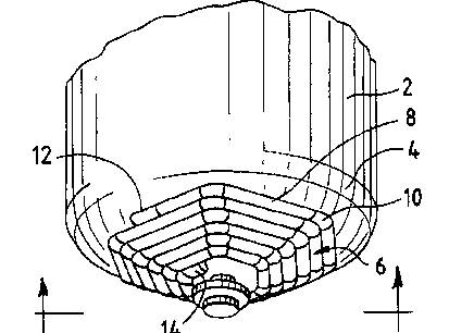
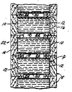
Thermal accumulators, e.g. using thermochemical reactions, using liquid heat storage material, e.g. with stratification of heat storage material, using the ground body as heat storage medium, using solid heat storage material.
Example:
US 4203489 A
Modular thermal energy storage system comprising individual thermal energy storage elements, each having a core (12) for storing thermal energy and an insulation layer (14, 16) surrounding the core,
Heat storage apparatus using latent heat (phase change materials) are classified in F28D 20/02.
Example:
US2012055661 A
High temperature thermal energy storage system comprising solid-liquid phase change material (106) that is fully encapsulated in helically grooved, sealed, metal tubes (104). Multitude of horizontally oriented, pressure-rated steam pipes or vessels (101) filled with PCM tube capsules form a battery of thermal storage system.
Control arrangements therefor, e.g. activators for initiating crystallisation of supercooled salt solution.
Attention is drawn to the following places, which may be of interest for search:
Arrangement of heat accumulators for vehicle heating, cooling or ventilating systems | |
Heat storage materials | |
Accumulating of heat within building walls | |
Gas-turbine plants having means for storing energy, e.g. for meeting peak loads | |
Radiant bodies for radiation heaters | |
Heat storage elements for stoves or ranges | |
Hot water storage tanks for hot-water central heating systems | |
Heating systems using heat storage with heat storage mass | |
Self contained storage heating units | |
Storage heaters | |
Solar collectors having heat storage mass | |
Devices using cold-storage bodies |
Attention is drawn to the following places, which may be of interest for search:
Heat storage plants using latent heat, the latent heat storage material being enclosed in granular particles or dispersed in porous, fibrous or cellular structure |
This place covers:
Residual group for F28D;
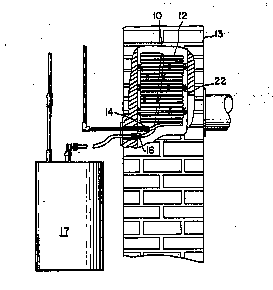
Also covers heat exchangers for particular use: recuperative heat exchangers, e.g. water heaters or air heaters for domestic or space-heating systems, the heat being derived from steam or hot-gas; heat exchangers having permeable walls for heat and mass transfer; Flooded core heat exchangers.
Example:
US 4484564 A
Preheater device (10) including a coil (12) formed from copper tubing, positioned in a flue (13) through which hot exhaust gases produced from the burning of fuel in a conventional furnace, flow. At the terminal end of the coil 12, the copper tubing passes through the intet. The inlet (14) is coupled to the main water line in a home. The outlet (16) is coupled to a domestic water heater 17.
Attention is drawn to the following places, which may be of interest for search:
Arrangements or adaptions of air-treatment apparatus for aircraft crew or passengers or freight space | |
Arrangements or adaptions of devices for temperature control of cosmonautic vehicles |
Attention is drawn to the following places, which may be of interest for search:
Heat exchange systems for engine or machine cooling systems |
Attention is drawn to the following places, which may be of interest for search:
Modifications to facilitate cooling, ventilating or heating of electric apparatus | |
Arrangements for cooling, heating, ventilating or temperature compensation of semiconductor or other solid-state devices |
Attention is drawn to the following places, which may be of interest for search:
Details of the cold heat exchange system of liquefaction equipment | |
Process for separating the constituents of gaseous mixture by rectification for air |
Attention is drawn to the following places, which may be of interest for search:
Radiators for space heating |
Attention is drawn to the following places, which may be of interest for search:
Drying gases or vapours by refrigeration or condensation |
Attention is drawn to the following places, which may be of interest for search:
Heat exchangers immersed in a natural body of water, e.g. marine radiators | |
Radiators for vehicles for recooling the engine coolant |
Attention is drawn to the following places, which may be of interest for search:
Auxiliary arrangements for fuel cells related to heat exchange |
Attention is drawn to the following places, which may be of interest for search:
Heat exchange apparatus using a fluidised bed |
Attention is drawn to the following places, which may be of interest for search:
Heat-exchange systems for vehicles or oil coolers |
Attention is drawn to the following places, which may be of interest for search:
Heating or cooling appliances for medical or therapeutic treatment of the human body |
Attention is drawn to the following places, which may be of interest for search:
Cooling arrangements within the pressure vessel containing the core; Selection of specific coolants |
Attention is drawn to the following places, which may be of interest for search:
Heat exchange for combustion apparatus, e.g. for boilers | |
Arrangements for using waste heat; Arrangements for using or disposing of waste gases |
Attention is drawn to the following places, which may be of interest for search:
Heat exchange apparatus in which the medium condenses and evaporates, e.g. heat pipes | |
Heat exchange apparatus for refrigerant cycles |
Attention is drawn to the following places, which may be of interest for search:
Steam or vapour condensers |
Attention is drawn to the following places, which may be of interest for search:
Condensers as heat exchange apparatus for vehicles | |
Condensers of refrigeration machines | |
Processes for separating the constituents of gaseous mixture involving the use of the liquefaction or solidification by partial condensation |
Attention is drawn to the following places, which may be of interest for search:
Evaporators as heat exchange apparatus for vehicles | |
Evaporators as refrigeration machines |
Attention is drawn to the following places, which may be of interest for search:
Cooling of cracked gases from thermal non-catalytic cracking, in the absence of hydrogen, of hydrocarbon oils |
Attention is drawn to the following places, which may be of interest for search:
Heat-exchange systems for aircrafts or cosmonautics |
Attention is drawn to the following places, which may be of interest for search:
Cooling of air intake supply of engines characterised by provision for charging or scavenging not provided for in groups F02B 25/00, F02B 27/00 or F02B 33/00 – F02B 39/00 |
Attention is drawn to the following places, which may be of interest for search:
Apparatus for thermally treating combustion-air, fuel or fuel-air mixture for cooling |
Attention is drawn to the following places, which may be of interest for search:
Heating, cooling or controlling temperature of lubricant |
Attention is drawn to the following places, which may be of interest for search:
Arrangements or mounting of liquid-to-air heat exchangers |
Attention is drawn to the following places, which may be of interest for search:
Heat exchangers for air-conditioning devices |
Attention is drawn to the following places, which may be of interest for search:
Heat-exchangers for foodstuffs |