CPC Definition - Subclass H03H
This place covers:
Apparatus or process specially adapted for the manufacture of impedance networks, resonating circuits or resonators, filters (H03H 3/00).
Impedance (matching) networks, resonating circuits or resonators and filters.
- Constructional (mechanical) details of impedance networks (H03H 1/00)
- Piezoelectric elements (with propagation of acoustic waves) (H03H 9/00)
- Electro-mechanical elements (H03H 9/00)
- Active elements (H03H 11/00)
- Sampled-data elements (H03H 15/00)
- Digital elements (H03H 17/00)
- Analog time varying elements, not digital (H03H 19/00)
- Adaptive techniques (H03H 21/00)
This place does not cover:
Waveguides, resonators, lines or other devices of the waveguide type |
Attention is drawn to the following places, which may be of interest for search:
Measuring or testing | |
Arrangements for producing a reverberation or echo sound | |
Resistors | |
Magnets, inductances, transformers | |
Capacitors, rectifiers, detectors, switching devices or light-sensitive devices of the electrolytic type | |
Electric power networks; Circuit arrangements or systems for supplying or distributing electric power; Systems for storing electric energy | |
Apparatus for conversion between AC and AC, between AC and DC or between DC and DC, and for use with mains or similar power supply systems | |
Impedance matching for amplifiers | |
Control of amplification, e.g. bandwidth control of amplifiers | |
Tuning resonant circuits, e.g. tuning coupled resonant circuits | |
Networks for modifying the frequency characteristics of communication systems | |
Arrangements for coupling to transmission lines | |
Impedance matching in integrated circuits |
This place covers:
Constructional details of impedance networks whose electrical mode of operation is not specified or applicable to more than one type of network (e.g. multilayered filters including lumped elements, feed-through filters. Mechanical details of filtering devices for medical equipment (A61) are to be classified in H03H 1/00.
This place does not cover:
Constructional details of electromechanical transducers |
Attention is drawn to the following places, which may be of interest for search:
Magnets, inductances, transformers per se, used as filter | |
Capacitors, rectifiers, detectors, switching devices or light-sensitive devices of the electrolytic type per se, used as a filter | |
Multilayered microwave filters including exclusively distributed elements like microstrip or transmission lines | |
Electric power networks; Circuit arrangements or systems for supplying or distributing electric power; Systems for storing electric energy | |
Apparatus for conversion between AC and AC, between AC and DC or between DC and DC, and for use with mains or similar power supply systems | |
Filters in multi-layer construction for PCBs |
In patent documents, the following abbreviations are often used:
RFI | radio frequency interference |
EMI | electromagnetic interference |
Attention is drawn to the following places, which may be of interest for search:
Printed circuits; Manufacture of assemblages of electrical components |
This place covers:
Networks using elements or techniques which are not provided for in groups H03H 3/00 - H03H 21/00
This place covers:
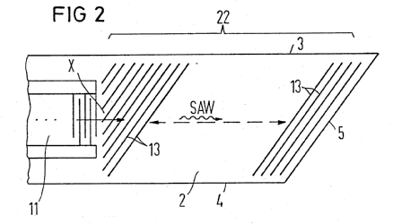
Manufacture of resonators, time-delay networks, phase-shifting networks, balanced/unbalanced networks and frequency selective networks, such as filters, splitters or duplexers -- all mainly built with surface or bulk acoustic wave devices, microelectromechanical system (MEMS) devices or electrostrictive or magnetostrictive devices. The devices per se are classified in H03H 9/00 and subgroups.
Attention is drawn to the following places, which may be of interest for search:
Manufacture of NEMS/MEMS details | |
Manufacture of constructional details involving semiconductor parts (e.g. layers, package, etc.) | |
Manufacture of transducers not involving resonance (e.g. ink dispatchers for printers) |
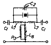
This place covers:
One-port networks comprising only passive electrical elements as network components, such as resistors, inductances, capacitances and diodes.
The group also covers LC resonators.
Attention is drawn to the following places, which may be of interest for search:
Simulation of reactances (e.g. active inductors, capacitor multipliers) with active elements | H03H 11/48 and subgroups |
Resistors | |
Magnets; Inductances; Transformers | |
Capacitors | |
Oscillators |
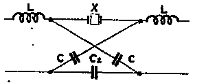
This place covers:
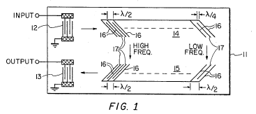
Gyrators, time-delay networks, phase-shifting networks, impedance matching networks, balanced/unbalanced networks, attenuators and frequency selective networks, such as filters, splitters or duplexers -- all mainly built with passive, lumped, electrical elements, such as resistors, capacitances, inductances and diodes.
When the time-delay networks, phase-shifting networks, impedance matching networks, balanced/unbalanced networks, attenuators and frequency selective networks, etc. are built mainly with passive, distributed, electrical elements, such as transmission lines, dielectric resonators, coaxial cables, then they are to be found and classified in H01P.
Examples of places where the subject matter of this place is covered when specially adapted, used for a particular purpose, or incorporated in a larger system:
Attention is drawn to the following places, which may be of interest for search:
RF interference and EMI filters | |
Hybrid couplers with passive lumped elements | |
Circulators, isolators with passive lumped elements | |
Simple balanced/unbalanced networks consisting only of coupled inductances (e.g. transformers) | |
Circulators, isolators with passive distributed elements | |
Balanced/unbalanced networks having lumped and distributed passive elements | |
Hybrid couplers with passive distributed elements | |
Electric power networks; Circuit arrangements or systems for supplying or distributing electric power; Systems for storing electric energy | |
Apparatus for conversion between AC and AC, between AC and DC or between DC and DC, and for use with mains or similar power supply systems | |
Attenuators for telecom transmission lines (phone, etc.) | |
Filters in audio frequency spectrum or in the sense of gain controlling | |
Attenuators in audio frequency spectrum or in the sense of gain controlling | |
Receiver input or transceiver output circuits for automatic impedance matching in telecommunications | |
Arrangements for coupling to transmission lines | |
CATV (power) splitters | |
Bandpass or bandstop filters for TV | |
In PCB embedded R, L, C elements for filtering | |
Manufacture/packaging of multilayer RLC filters |
In patent documents, the following abbreviations are often used:
Balun | BALanced/UNbalanced network |
This place does not cover:
Filters comprising mutual inductance |
Attention is drawn to the following places, which may be of interest for search:
Automatic control of bandwidth in amplifiers |
Examples of places where the subject matter of this place is covered when specially adapted, used for a particular purpose, or incorporated in a larger system:
For use in multiplex transmission systems |
This place covers:
Resonators, time-delay networks, phase-shifting networks, balanced/unbalanced networks and frequency selective networks, such as filters, splitters or duplexers -- all mainly build with surface or bulk acoustic wave devices, microelectromechanical system (MEMS) devices or electrostrictive or magnetostrictive devices.
This place does not cover:
Electro-acoustic transducers such as loudspeakers, microphones or gramophone pick-ups | |
Piezoelectric, electrostrictive magnetostrictive devices with mechanical input or output, e.g. actuators or sensors |
Attention is drawn to the following places, which may be of interest for search:
SAW tuning | |
MEMS transducers not involving resonance | |
Mirror of BAW devices - manufacture | |
SAW/MEMS/BAW devices for sensing applications (when no particular emphasis is made for the constructional details or filtering, and focus is on sensing) | |
RF ID tags | |
Constructional details involving semiconductor parts (e.g. layers, package, etc.) |
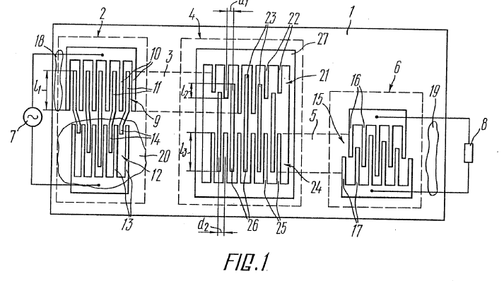
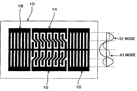
Further details of subgroups
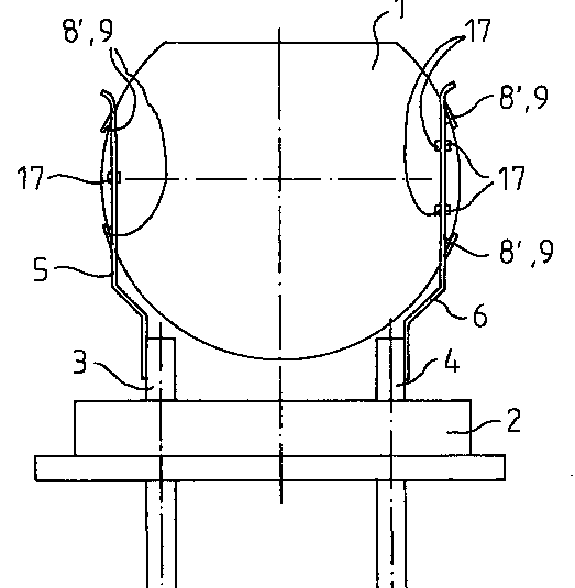
The documents classified in H03H 9/0023 relate to balance-unbalance or balance-balance networks.
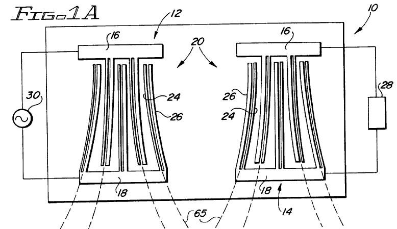
The main aspect present in BALUN device is the phase inversion. In a device presenting an unbalanced (non-differential) input and output, the output signal is referred to the ground. The BALUN device obtains additionally at the second terminal of the output port (this is why it needs a differential port) a signal presenting the same characteristics of the signal present on the first terminal of the output port, but in opposition of phase w.r.t the signal at the first terminal. The device generates therefore the phase inversion.
Devices presenting a "balanced input-balanced output" structure are also considered as BALUN as by connecting one of the terminals of one of the ports to the ground the whole device transforms in a BALUN according to the above definition.
BALUN are also to be seen as impedance matching devices (although not classified as such) as they perform in general an impedance transformation between input and output ports.
Only documents concerning BALUN networks comprising MEMS elements have to be found in H03H 9/0023.
Balance-unbalance or balance-balance networks using surface acoustic wave devices are classified in H03H 9/0028+.
Balance-unbalance or balance-balance networks using bulk acoustic wave devices are classified in H03H 9/0095.
If there are embodiments covering BALUN networks comprising different type of elements (e.g. one embodiment about a saw BALUN network, and another one about a baw BALUN network), the document should be classified in the respective classes.
BALUN = BALanced-UNbalanced
SAW BALUN devices are SAW devices presenting a unbalanced port (i.e. "hot" terminal + ground) and a balanced port (i.e. two "hot" terminals being responsive of generating/receiving signals in opposition of phase).
The main aspect present in BALUN device is the phase inversion. In a device presenting an unbalanced (non-differential) input and output the output signal is referred to the ground. The BALUN device obtains additionally at the second terminal of the output port (this is why it needs a differential port) a signal presenting the same characteristics of the signal present on the first terminal of the output port, but in opposition of phase w.r.t the signal at the first terminal. The device generates therefore the phase inversion.
As means for phase inversion one could mention:
- reversing the polarities of the IDTs (e.g. SA411059, DE19818038);
- using horizontally/vertically split IDTs (e.g. DE19818038, XP977738, XP977546);
- use of different gaps between IDTs or reflectors (EP02290698; EP0800270-fig. 7; WO0069069; EP01400393);
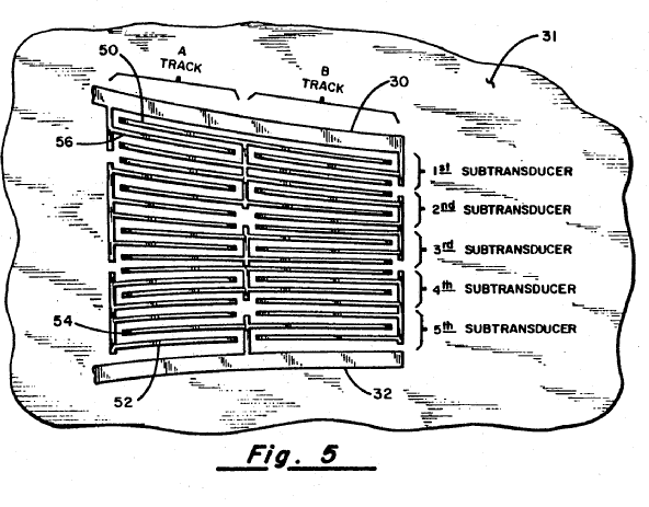
- shifted position of fingers (LAMBDA/2) in a multitrack configuration (EP1221769);
- producing an asymmetry w.r.t. the central line (EP02291909).
SAW devices presenting a "balanced input-balanced output" structure are also considered as BALUN as by connecting one of the terminals of one of the ports to the ground the whole device transforms in a BALUN according to the above definition.
BALUN are also to be seen as impedance matching devices (although not classified as such) as they perform in general an impedance transformation between input and output ports.
This class takes precedence before H03H 9/6433+, i.e. whenever a SAW coupled resonator filter presents the features of a BALUN device it is to be classified in H03H 9/0028. It goes without saying that a document disclosing also a separate embodiment dealing exclusively with matters specific to H03H 9/6433+ has to be classified in the corresponding H03H 9/6433+ class, too.
Indexing Codes or KWs describing other aspects related to the BALUN devices (like matching, etc.) also take precedence before corresponding Indexing Codes or KWs describing aspects related to the SAW coupled resonator filters
NOTE
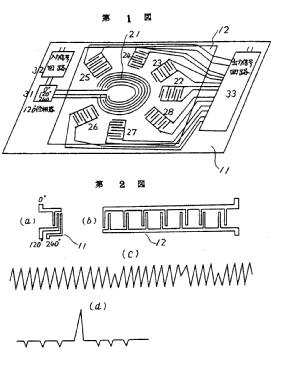
Horizontally split IDTs like in the figure below (3) although might fall under the scope of the present subclass need also to be classified according to the existing KW (09 split IDT horizontally).
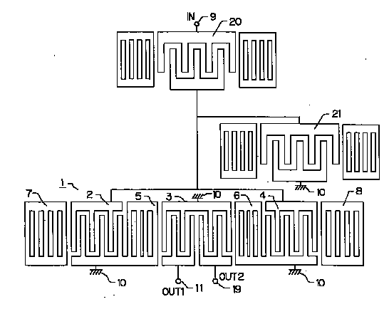
Fig. 1
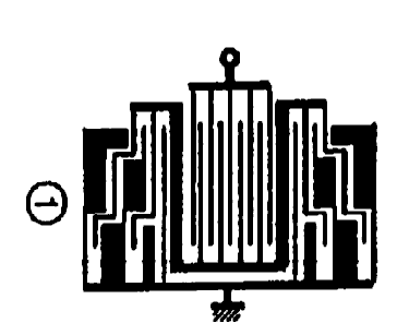
NOTE
Vertically split IDTs like in the figure below (1401) although fall under the scope of the present subclass need also to be classified corresponding to /KW (09 split IDT vertically) has to be assigned.
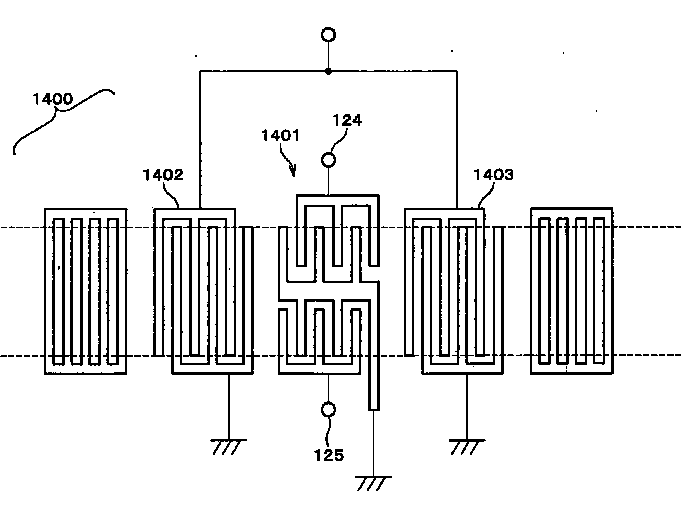
Fig. 2
The documents classified in H03H 9/0095 relate to balance-unbalance or balance-balance networks using bulk acoustic wave devices.
Note:
H03H 9/0095 takes precedence over H03H 9/566 and H03H 9/60.
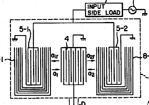
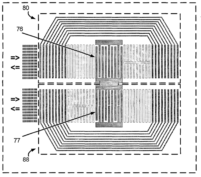
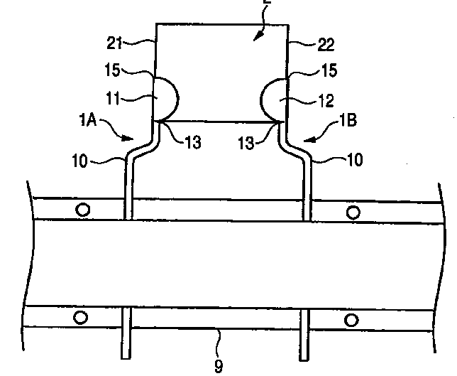
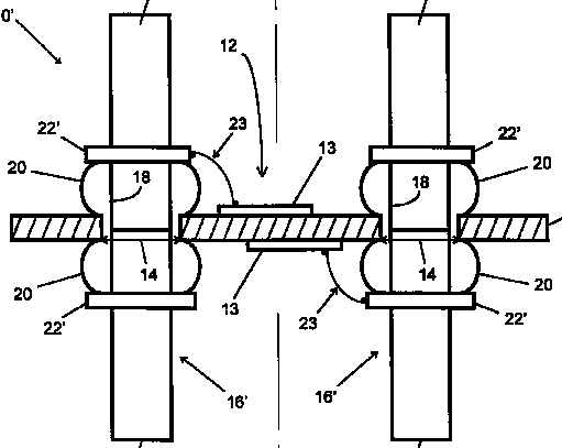
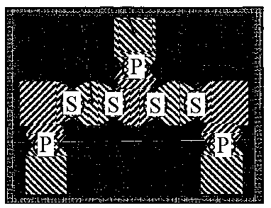
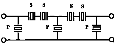
The lattice configuration of resonators is a balance-balance network, and is of this type:
There are various possibilities of such networks:
For general remarks concerning BALUN devices refer to the description of class H03H 9/0028 in the Definition Editor.
In the present class (H03H 9/0038) are classified documents having:
a) only one acoustic track performing the filtering; and
b) the (two) terminals of the balanced port(s) are on the same side of the acoustic track.
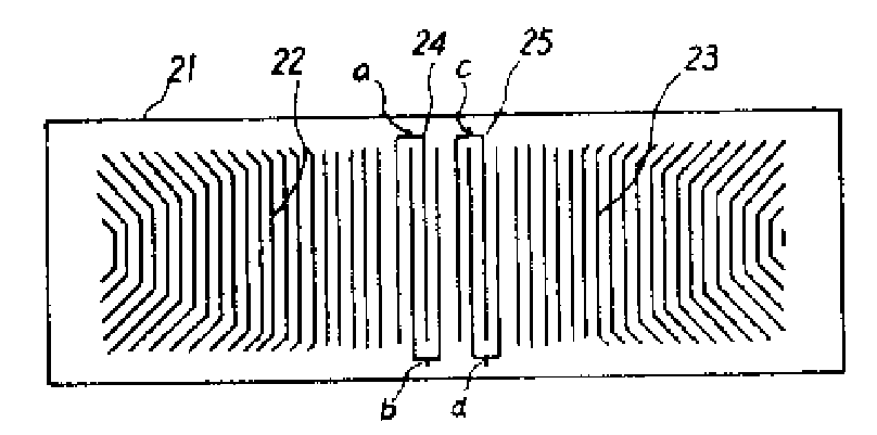
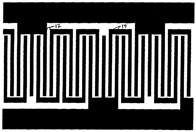
An example is to be found here below (balanced terminals are referenced with numerals 5 and 6):
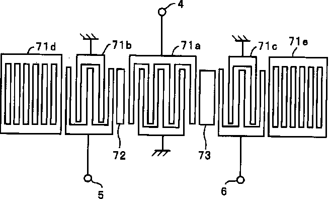
Fig. 1
The mere fact that the balanced and/or unbalanced port has serial connected resonators like "ser A" in Fig. 2 below does not change the attributes taken into account for the classification - BALUN structure having the terminals of the balanced port on the same side of the acoustic track.
The problem solved by the series resonators is most of the time one of improving the steepness of the transition band of the filter. For this purpose the series resonators have to be designed with the resonance frequency having a value which coincides with the beginning of the transition band and the end of the 3dB portion of the pass band.
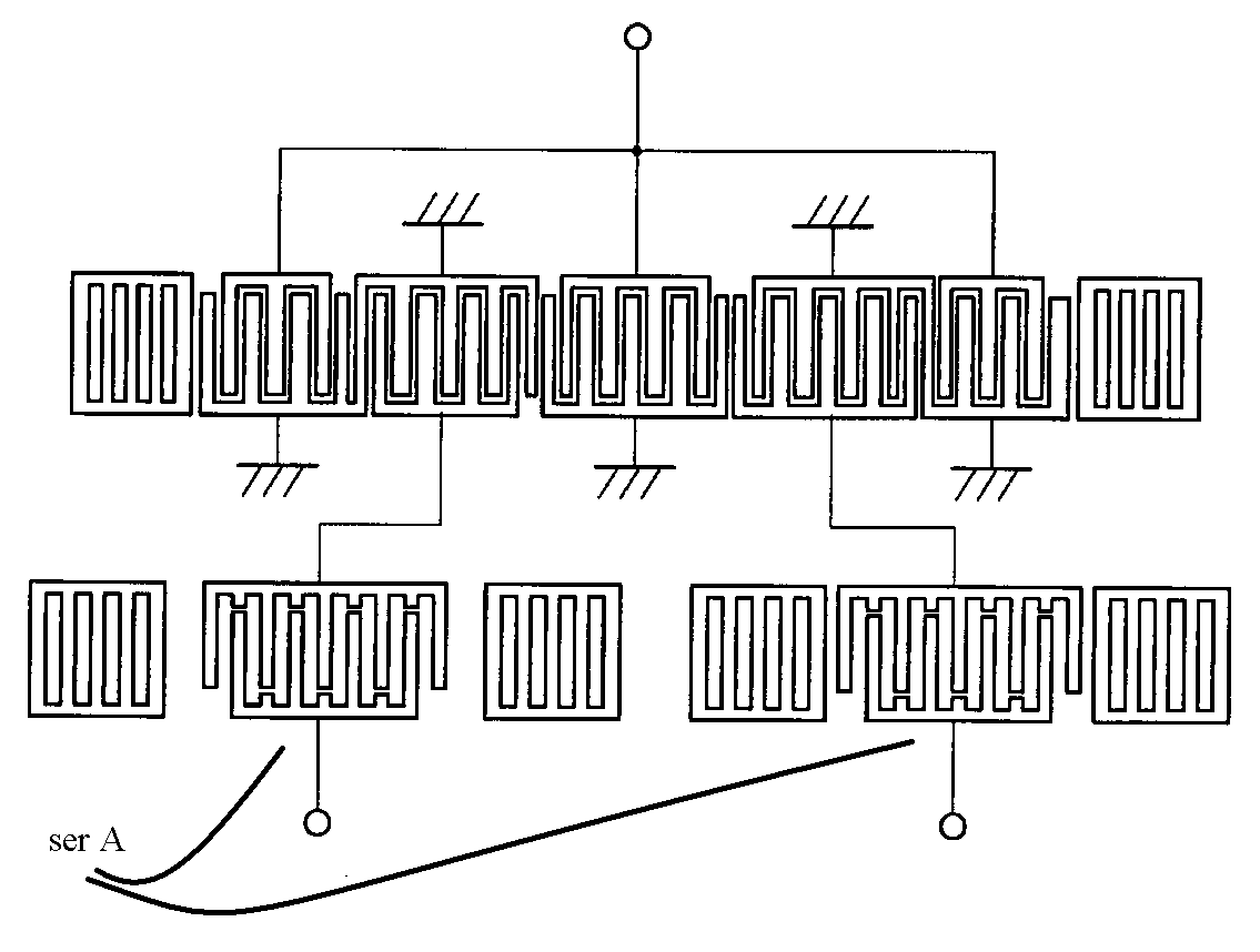
Fig. 2
For general remarks concerning BALUN devices refer to the description of class H03H 9/0028 in the Definition Editor.
In the present class (H03H 9/0042) are classified documents having:
a) only one acoustic track performing the filtering; and
b) the (two) terminals of the balanced port(s) are disposed on opposite sides of the acoustic track.
An example is to be found here below (balanced terminals are referenced OUT1 and OUT2):
Fig. 1
The mere fact that the balanced and/or unbalanced port has/have series connected resonators like those referenced with the numbers (5, 6) in Fig. 2 below does not change the attributes taken into account for the classification - BALUN structure having the terminals of the balanced port on opposite sides of the acoustic track.
The problem solved by the series resonators is most of the time one of improving the steepness of the transition band of the filter. For this purpose the series resonators have to be designed with the resonance frequency having a value which coincides with the beginning of the transition band and the end of the 3dB portion of the pass band.
Fig. 2
For general remarks concerning BALUN devices refer to the description of class H03H 9/0028 in the Definition Editor.
In the present class (H03H 9/0057) are classified documents having the following features:
a) two acoustic tracks performing the filtering;
b) the two acoustic tracks are electrically cascaded (between the input and output of the whole device); and
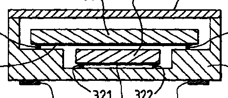
c) the (two) terminals of the balanced port(s) are disposed on the same side of the last acoustic track in the cascaded structure.
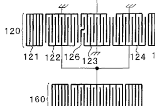
An example is to be found here below (balanced terminals are referenced (124) and (125)).
Fig. 1
The mere fact that the balanced and/or unbalanced port has/have series connected resonators like those referenced with number (R11+W1+R12) in Fig. 2 below does not change the attributes taken into account for the classification - BALUN structure having the terminals of the balanced port on the same side of the output acoustic track.
The problem solved by the series resonators is most of the time one of improving the steepness of the transition band of the filter. For this purpose the series resonators have to be designed with the resonance frequency having a value which coincides with the beginning of the transition band and the end of the 3dB portion of the pass band.
Fig. 2
BALUN structures of the type presented in Fig. 3 below are also to be classified in the present class (H03H 9/0057).
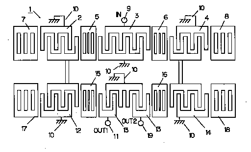
Fig. 3
For general remarks concerning BALUN devices refer to the description of class H03H 9/0028 in the Definition Editor.
In the present class (H03H 9/0071) are classified documents having the following features:
a) two acoustic tracks performing the filtering;
b) the two acoustic tracks are electrically parallel connected (between the input and output of the whole device); and
c) the (two) terminals of the balanced port(s) are disposed on the same side of the output acoustic track in the cascaded structure.
An example is to be found here below (balanced terminals are referenced (5) and (6)).
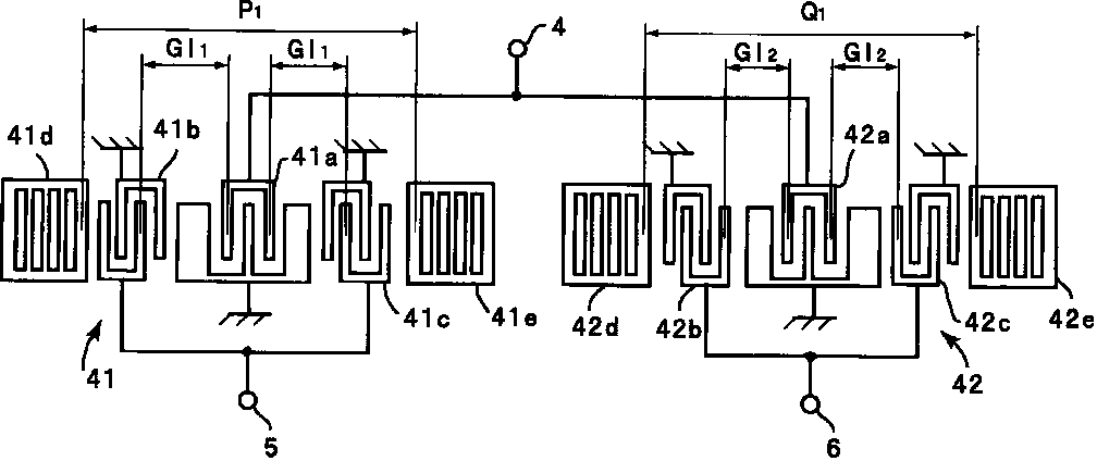
Fig. 1
The mere fact that the balanced and/or unbalanced port has/have series connected resonators like those referenced with the numbers (30, 40) in Fig. 2 below does not change the attributes taken into account for the classification - BALUN structure having the terminals of the balanced port on the same side of the output acoustic track.
The problem solved by the series resonators is most of the time one of improving the steepness of the transition band of the filter. For this purpose the series resonators have to be designed with the resonance frequency having a value which coincides with the beginning of the transition band and the end of the 3dB portion of the pass band.
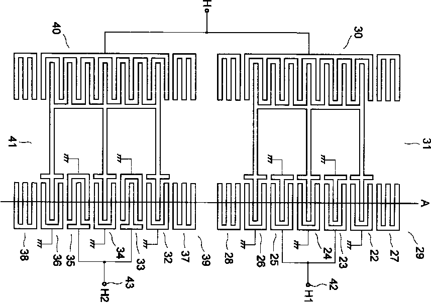
Fig. 2
For general remarks concerning BALUN devices refer to the description of class H03H 9/0028 in the Definition Editor.
In the present class (H03H 9/0061) are classified documents having the following features:
a) two acoustic tracks performing the filtering;
b) the two acoustic tracks are electrically cascaded (between the input and output of the whole device); and
c) the (two) terminals of the balanced port(s) are disposed on opposite sides of the output acoustic track in the cascaded structure.
An example is to be found here below (balanced terminals are referenced (out1) and (out2)). It is to be noticed that in this drawing the input (in1+in2) is also balanced having terminals on opposite sides of the input acoustic track.
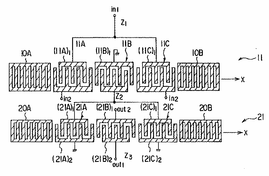
Fig. 1
The mere fact that the balanced and/or unbalanced port has/have series connected resonators like those referenced with number (324) in Fig. 2 below does not change the attributes taken into account for the classification - BALUN structure having the terminals of the balanced port on opposite sides of the output acoustic track.
The problem solved by the series resonators is most of the time one of improving the steepness of the transition band of the filter. For this purpose the series resonators have to be designed with the resonance frequency having a value which coincides with the beginning of the transition band and the end of the 3dB portion of the pass band.
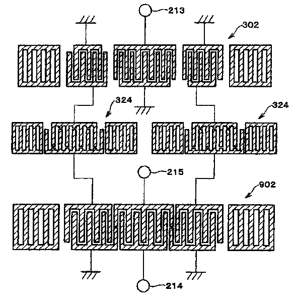
Fig. 2
BALUN structures of the type presented in Fig. 3 below are also to be classified in the present class (H03H 9/0061).
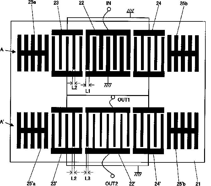
Fig. 3
For general remarks concerning BALUN devices refer to the description of class H03H 9/0028 in the Definition Editor.
In the present class (H03H 9/0076) are classified documents having the following features:
a) two acoustic tracks performing the filtering;
b) the two acoustic tracks are electrically parallel connected (between the input and output of the whole device); and
c) the (two) terminals of the balanced port(s) are disposed on opposite sides of the output acoustic track in the cascaded structure.
An example is to be found here below (balanced terminals are referenced (16) and (46)).
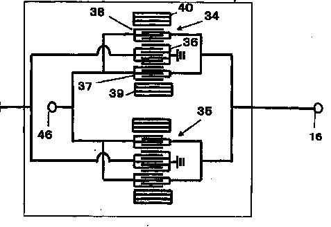
Fig. 1
For general remarks concerning BALUN devices refer to the description of class H03H 9/0028 in the Definition Editor.
In the present class (H03H 9/008) are classified documents having three acoustic tracks performing the filtering.
Most of the times the three acoustic tracks are electrically cascade-parallel connected (between the input and output of the whole device) as in Fig. 1.
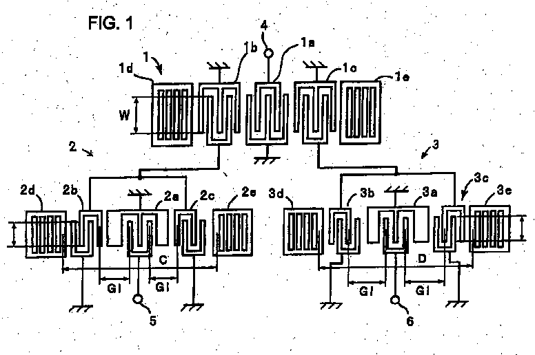
Fig. 1
For general remarks concerning BALUN devices refer to the description of class H03H 9/0028 in the Definition Editor.
In the present class (H03H 9/0085) are classified documents having the following features:
a) four acoustic tracks performing the filtering; and
b) the four acoustic tracks are electrically cascade-parallel connected (between the input and output of the whole device) as in Fig. 1-3 below.
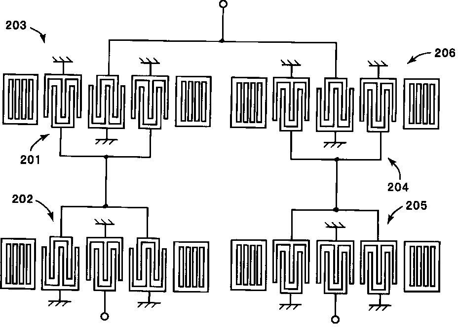
Fig. 1
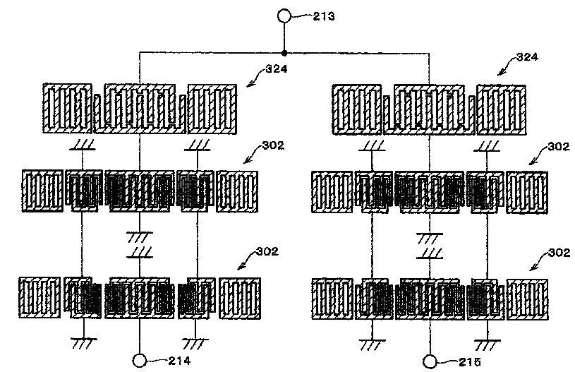
Fig. 2

The documents classified in H03H 9/02007 relate to details of bulk acoustic wave devices, especially about vibration mode or dimensional parameters of baw devices.
1/ Details about vibration mode of baw devices should be classified as follows:
a) Details about harmonic vibration
In some baw devices, instead of the fundamental, one or more harmonic (aka multiple of the fundamental frequency) are excited. Sometimes harmonic mode is also called overtone mode.
These documents should be classified in H03H 9/02007 and provided with the following keyword:
09 02b baw details vibration mode harmonic (H03H)
b) Details about overmoded vibration
Overmoded baw devices comprise a substrate with a thickness that is a multiple of the wavelength in order to operate at a large mode number and to exhibit a high Q impedance response.
In an overmoded resonator, multiple resonance occurs at frequency intervals determined by the fundamental resonant frequency.
These documents should be classified in H03H 9/02007 and provided with the following keyword:
09 02b baw details vibration mode overmoded (H03H)
There are different types of baw devices being considered as overmoded.
This type of overmoded resonators should also be classifed in H03H 9/172:
These types of overmoded filters should also be classifed respectively in H03H 9/585 and H03H 9/584:
2/ Details of dimensional parameters (length, width, thickness) of baw devices should be classified as follows:
Documents dealing with details about a ratio between two of the dimension parameters in order to improve the characteristics of the bulk acoustic wave device should be classified in H03H 9/02007 and provided with the following keyword::
09 02b baw details dimensional parameters (H03H)
Details about the characteristics of piezoelectric layers are classified in H03H 9/02015+.
Details about treatment of substrates are classified in H03H 9/02047+.
Details about means for compensation of undesired effects are classified in H03H 9/02086+.
Details about the electrodes of baw devices are classified in H03H 9/13 and especially provided with the keyword 09-13 baw formation (H03H).
The documents classified in H03H 9/02015 relate to characteristics of piezoelectric layers.
Documents dealing with cutting angles of the piezoelectric layers or with the properties of the piezoelectric layer have to be found in H03H 9/02015.
Documents dealing with the resonator or the filter itself are classified respectively in H03H 9/17+ and in H03H 9/54+.
Piezoelectric layers of the quartz type are classified in H03H 9/02023.
Piezoelectric layers of the ceramic type are classified in H03H 9/02031.
Piezoelectric layers of the group 32 type are classified in H03H 9/02039.
The documents classified in H03H 9/02023 relate to characteristics of piezoelectric layers of the quartz type.
The documents classified in H03H 9/02031 relate to characteristics of piezoelectric layers of the ceramic type.
Ceramic materials are::
LiTaO3 (lithium tantalate), LiNbO3 (lithium niobate), AlN (aluminium nitride),Ta2O5, (Ba,Sr)TiO3 (BST), Pb(Zr,Ti)O3 (PZT, lead zirconate, lead titanate), SrBi2Ta2O9(SBT), KNbO3 (potassium niobate), Perovskite type, Pb0.99Nb0.02(Zr0.85 Sn0.13 Ti0.02)0.98O3 (PNZST), Pb0.97La0.02(Zr0.65 Sn0.31 Ti0.04)O3 (PLZST, PLZT), Wurtzite type.
The documents classified in H03H 9/02039 relate to characteristics of piezoelectric layers of the group 32 type.
Materials of the group 32 are:
Langasite (La3Ga5SiO14), Pr3Ga5SiO14, Nd3Ga5SiO14, Langatate (La3Ga5.5Ta0.5O14), Langanite (La3Ga5.5Nb0.5O14), Sr3TaGa3Si2O14, Ca3Ga2Ge4O14, Ca3NbGa3Si2O14, GaPO4, AlPO4, Berlinite
The documents classified in H03H 9/02047 relate to the treatment of substrates of bulk acoustic wave devices in order to reduce spurious vibrations.
The documents classified in H03H 9/02055 relate to treatment of the back surface of the substrate of bulk acoustic wave devices.
For example, the bottom surface of the substrate is roughened to reduce the reflection of acoustic waves:

The documents classified in H03H 9/02086 relate to bulk acoustic wave devices with means for compensation or elimination of undesirable effects.
1/ Undesired effects caused by parasitic elements
The aim is to prevent cross-talk (image current) between bulk acoustic wave elements on the same substrate across parasitic capacitances. Also called capacitive coupling.
These documents should be classified in H03H 9/02086 and provided with the following keyword:
09 02b8 baw details undesired effects parasitic elements (H03H)
2/ Undesired effects caused by lateral leakage between adjacent resonators
The aim is to prevent unwanted laterally propagating waves generated by one resonator from interfering with an adjacent one.
These documents should be classified in H03H 9/02086 and provided with the following keyword:
09 02b8 baw details undesired effects lateral leakage (H03H)
3/ Undesired effects caused by adherence problems
The aim is to improve the adherence between two layers by:
- providing an adhesion layer
- modifying the orientation of at least one of the layers
For increase of adherence for mounting in enclosures, see H03H 9/10.
These documents should be classified in H03H 9/02086 and provided with the following keyword:
09 02b8 baw details undesired effects adherence (H03H)
Documents dealing with temperature compensation are classified in H03H 9/02102.
Documents dealing with compensation of reflections are classified in H03H 9/0211.
Documents dealing with compensation of stress are classified in H03H 9/02133.
Documents dealing with compensation of electric discharge due to pyroelectricity are classified in H03H 9/02141.
Documents dealing with compensation of ageing changes are classified in H03H 9/02149.
The documents classified in H03H 9/02102 relate to bulk acoustic wave devices with means for compensation of temperature influence.
Temperature compensation can be achieved in resonator devices by using
piezoelectric materials that already have a high degree of temperature stability or through
composite structures containing offsetting ratios of positive and negative coefficient materials.
One temperature compensation approach is to use a composite structure and balance positive TC and negative TC materials to obtain a satisfactory degree of temperature compensation. For example, the normally negative temperature coefficient of AlN (-25 ppm per deg C) and ZnO (-60 ppm per deg C) can be offset to a degree by the positive coefficient of silicon dioxide in film form (+85 ppm per deg C).
The documents classified in H03H 9/0211 relate to bulk acoustic wave devices with means for compensation of reflections.
The aim is to prevent unwanted vibration due to non horizontal vibration leakage, thereby suppressing occurrence of spurious components.
The documents classified in H03H 9/02133 relate to bulk acoustic wave devices with means for compensation of stress.
The aim is to prevent stress in order to avoid:
- internal stress by having it evenly applied
- formation of cracks
One possibility is the use of low tensile stress material.
The documents classified in H03H 9/02141 relate to bulk acoustic wave devices with means for compensation of electric discharge due to pyroelectricity.
The documents classified in H03H 9/02149 relate to bulk acoustic wave devices with means for compensation of ageing changes, e.g. atoms diffusion.
The aim is to prevent the problem of chemical interaction between two metals and specially the migration of atomic charges from one layer to an other (electromigration).
To avoid migration between different layer of a multiple layer electrode.
To avoid migration between the piezoelectric layer and an electrode layer, a diffusion barrier, or a barrier layer is provided.

Electrode corrosion or oxidation, due to humidity (air contact) has also to be classify here.
There is provided a protective layer or a passivation layer in order to protect the electrode.
The classes H03H 9/02637+ accommodate documents disclosing particular reflective or coupling entities for both SAW resonators and SAW filters.
Note:
Seen the relatively high degree of indentation it is meant to keep the root rather empty.
Redundancies:
1) H03H 9/643 appears to overlap the classes H03H 9/02637+. From now on, no new documents should be classified in H03H 9/643. This class will be deleted in the future and the documents still in there will be reclassified accordingly (it is expected to move most of them in H03H 9/02637+)
2) Idem for the SAW documents in H03H 9/48, H03H 9/50, H03H 9/52. These classes are already cleaned out now of any SAW devices.
BAW and MEMS are still to be classified in these classes and their subclasses if needed.
3) The is a certain overlap between H03H 9/44 and H03H 9/02637+ concerning in particular the reflective/pulse array compressors (RAC, PAC). Currently this overlap is not an issue, as apparently no new docs enters.
Reflector gratings are replaced with dot arrays better performing from the point of view of e.g. spurious/ripple.
For example, GB2060305 says:
"In most applications it is desirable to vary the strength of reflection from different grooves or strips within the array to provide amplitude weighting, and in the case of metallic strip array this cannot be done in a simple controllable manner.
To overcome this limitation of metallic strip arrays, while retaining its advantages, it has been proposed to replace each reflective metal strip with a row of metallic dots."
US4204178

GB2060305
The grooves could be empty, partially or totally filled with material, and they could be between (but not inside) IDTs or side-framing them. When they are inside the IDTs,
US4237433
US4204178
The grooves could be emptied of filled with material and should be only inside the IDTs.
US4454488
US4130813
US2004095038
SAW devices having no grating reflectors, but edges cut at the appropriate position in order to produce the reflection of the waves launched by IDTs and therefore to define a resonant cavity to which the SAW waves are confined.
It to be noticed that the former name of this class (originally under H03H 9/02669) was changed by removing from the list of examples the shear horizontal (SH), shear transversal (ST) and Love waves for which it is not granted that one has an edge reflective arrangement.
EP1030445
US5781083
Edge reflecting SAW devices whose propagation substrates have complex cutting at the reflective end in order to improve parts of the frequency characteristics (e.g. side lobe suppression, ripple, etc.).
WO2005050836

US2003034859 US2003071539
US5287036
The class accommodates documents disclosing particular reflective gratings for both SAW resonators and SAW filters.
When the reflector shape is apparently a common one, but is however of importance for the subject-matter of the document (e.g. dimensions and positioning of the reflector is of great importance for the inventions like in JP57063920, below), the document should also receive H03H 9/02685:
JP57063920
"Non-standard", complex shapes of reflective entities would also get a class in H03H 9/02637:
US4210883
US2004075511

JP61061512
The class accommodates documents disclosing partially circular, elliptic, hyperbolic, or more generally curved shapes.
US4013983
US4038614
CA966588
The class accommodates documents disclosing U-, V- or round L-shaped grating lines
CA966588
US2004096139
DE4228223
US4468642
JP61004316
JP55153418
The class accommodates documents disclosing grating lines which are piecewise linear, but not straight. These kind of reflective arrays improve the broadness of the band and reduce dispersion. See for analogy the corresponding class under H03H 9/145 for shifted transducers (currently the right entry in H03H 9/145 could not be given due to reorganisation works in there).
GB2175477
US2004096139

US2003193668
The class accommodates documents disclosing tilted, fan shaped or slanted grating lines. Sometimes the docs should be classified in the chirp reflectors class, too.

WO9717757
US4801836
DE3731309
US4801836 (see comb like gratings 16)
(see comb like gratings 54, 55)
The comb like reflectors have a median short circuiting line:
US2004096139

EP1926210
Grating lines are floating or grounded and disposed inside the IDTs:

JP60263505
WO8002090

EP1463200
Grating lines of meander form are floating or grounded and disposed inside the IDTs. Apparent overlaps subject-matter of H03H 9/14508 (polyphased IDTs), but there the meandering electrode(s) are connected to a hot wire phase (i.e. neither grounded nor floating).
XP000977542
US2003067370
EP0337703
The reflectors on the left and right side of the (filter) resonator are electrically connected on the substrate via a comb electrode which is part of the IDT (and obviously connected to ground or floating) (see US5363073), or via an intermediate reflector disposed inside the IDT arrangement (EP1276236), or otherwise (XP000439202).

EP1276236
US5363073
Sometimes U-shaped reflectors are "eligible" for the present class, too:
XP000439202
Reflector banks contain more than two reflective patterns in the same reflector unit, or the reflector unit has of at least two separated groups of identical patterns reflectors, which are mutually spaced.
CA966588
XP008032241
US4340834
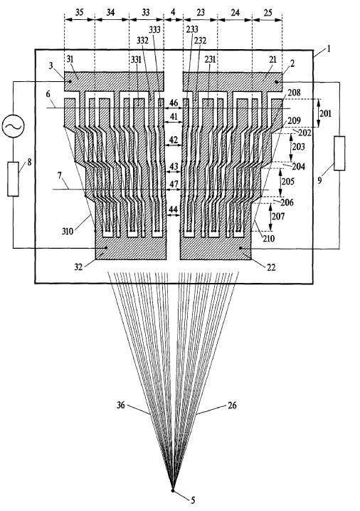
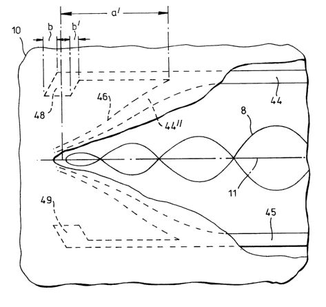
Continuous, "massive" (most of the times) metallic or electrically conductive deposition which is meant to reflect the SAW waves to a certain direction, and to attract the skimming component of the waves to the surface and therefore improve the directivity and frequency content of the surface acoustic waves by reflections and self cancellation of harmonic components.
It has not to be confounded with wave guides which have the dominant dimension (let's call it length) oriented in the direction of propagation of the useful SAW (see H03H 9/02661).

GB2000409
DE4313981

EP1926210
Sometimes the conductive deposition mentioned in H03H 9/02653 also has the role of focusing the surface acoustic waves in order to reduce the dispersion or simply to direct it to (usually) output IDTs. The shape should be adequately designed, that is the length of the metallic deposition, which also should be its dominant dimension, is oriented in the propagation direction of the waves.
FR2788176 (this wave guide is a track changer, too - see note below)
DE19822501
US5717274
Notes:
a) Confusion should be avoided with H03H 9/02795, where the track changers are made of strips:
US4336514
b) Documents in which the conductive deposition sets the goal of separating propagation path on the substrate are only to be classified in H03H 9/02905. For example:
US2005156687
JP57063921
Could be chirped, where another classification entry (e.g. H03H 9/02811 ) is also allocated:
US4336514
The couplers could be also dot arrays,
GB2060305
simple gratings,
GB2000409
arched gratings,
US4749971
or U-shaped gratigs:
CA966588
Inclined track changers, like US4336514 or GB2060305 above, are also classified in H03H 9/02716.
Weighing could be done by any method (i.e. apodisation, withdrawal, thickness etc.)
US2005001696
DE4213117

US4155056
The chirped arrangement is well know for its advantages on e.g. achieving broad band spectra, reducing the length of the substrate or the resultant ripple.
The chirped arrangement applies to dot arrays, multi-strip couplers (MSC), apparent floating or shorted strips reflectors or grooves:
GB2214020 (MSC type)
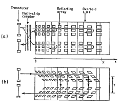
XP010075436

JP56078219 (shorted strips reflector type)
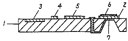
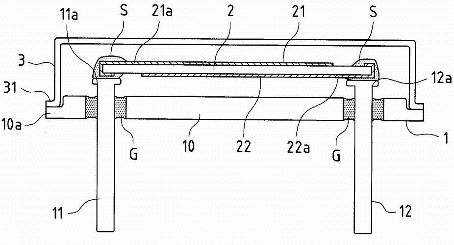
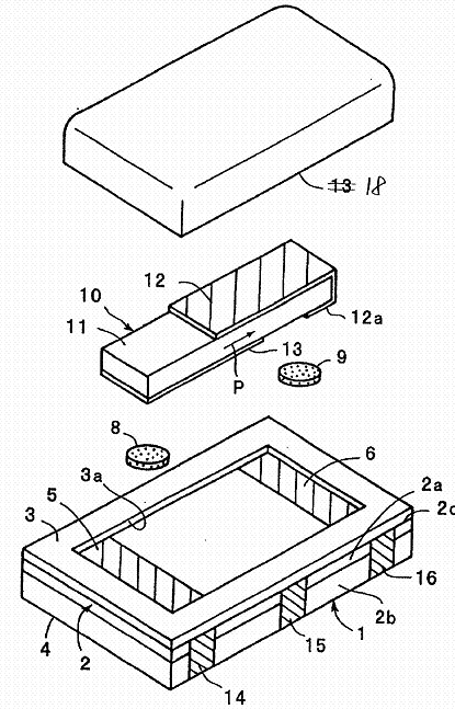
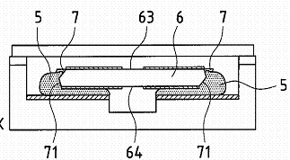
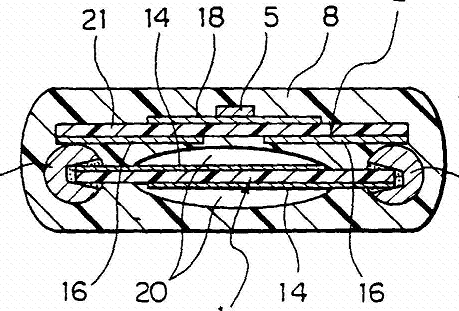
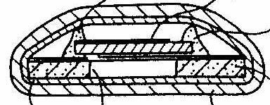
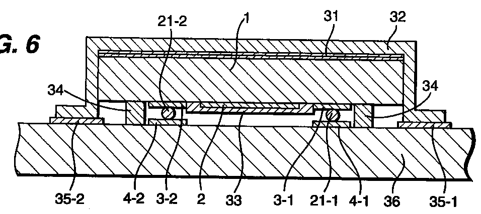
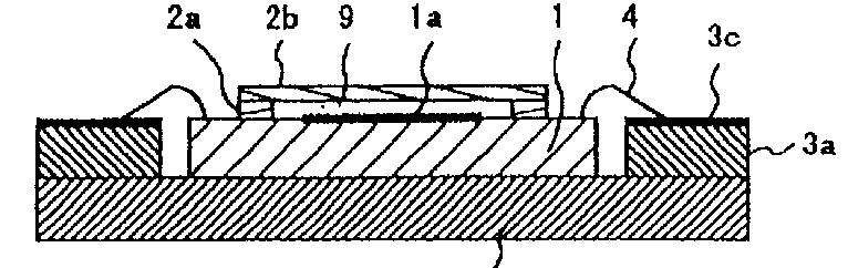
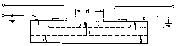
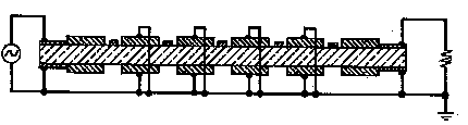
The documents classified in H03H 9/0504 relate to holder and supporting means details for BAW devices.
If the supporting means consist of temperature regulation means, then classify also in H03H 9/08.
If the supporting means consist of elastic or damping means, then classify also in H03H 9/09.
Note: Manufacture details about holder and supporting means details should not be classified in the manufacture classes. (i.e H03H 3/00 and subgroups)
The holder and supporting means consisting of adhesive.
JP 59144213
GB 1419680
In some cases, the adhesive is surrounding the side ends of the BAW device.
US 5945774
US 6141844
The holder and supporting means consisting of mounting pads or bumps.
US 5030876
EP 1067684
US 4486681
JP 59133721
WO 03100876
US 4967166
The holder and supporting means consisting of mounting pads or bumps for cantilever.
Note: H03H 9/1021 takes precedence over H03H 9/0519 (unless there is a lot of details about the supporting means of the cantilever).
EP 1187322
JP 53071597
WO 9831095
The holder and supporting means consisting of mounting pads or bumps for flip-chip mounting.
US 2003/186673
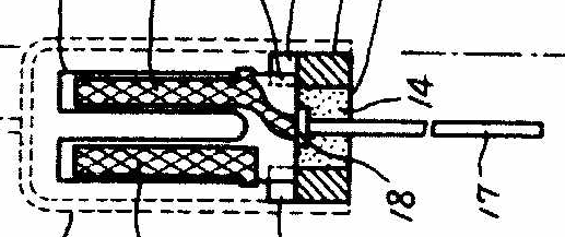
The holder and supporting means consisting of clips.
The piezoelectric device is held between two supporting means.
The two supporting means are shaped to exert a gripping pressure.
GB 1175244
DE 29900259U
US 2005140250
US 5834881
US 6087763
EP 0083237
The holder and supporting means consisting of wire.
GB 1219066
US 4065684
JP 56138315
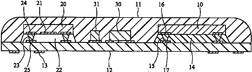
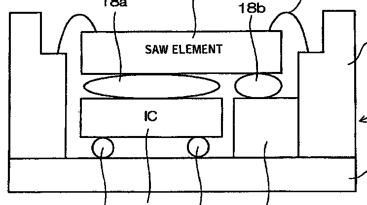
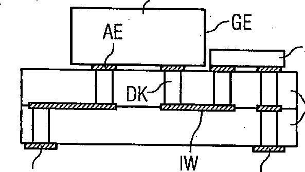
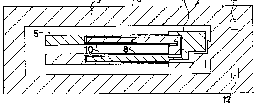
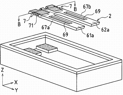
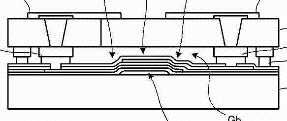
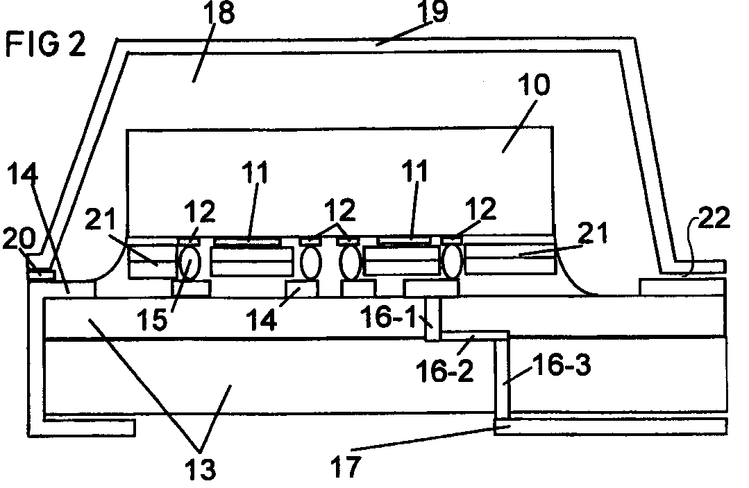
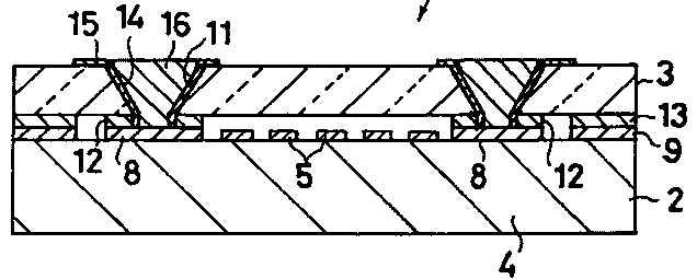
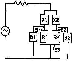
The documents classified in H03H 9/0538 relate to details of arrangement of electromechanical device(s) with other electronic component(s).
Documents classified in H03H 9/0538 and lower disclose details of the way the electromechanical devices and the other electronic components are arranged together.
Details about lateral arrangement are classified in H03H 9/0542+.
Details about vertical arrangement are classified in H03H 9/0547+.
Details about BAW/SAW duplexers arrangement are classified in H03H 9/0566+.
Note:
Documents concerning duplexers should not be classified in H03H 9/0538 and lower but in the duplexer classes (H03H 9/706 and H03H 9/725).
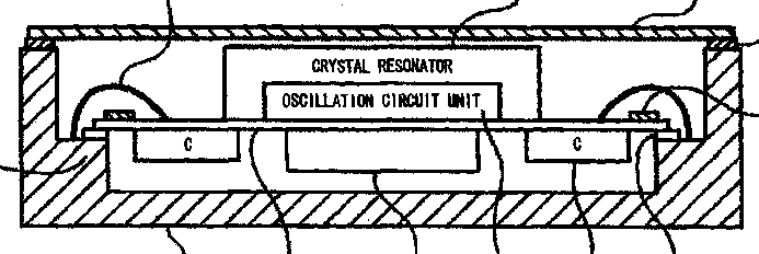
The documents classified in H03H 9/0542 relate to a lateral arrangement of the electromechanical device(s) and the other electronic component(s).
The components are disposed substantially on the same plane creating a lateral arrangement.
For the time being, documents should be classified in H03H 9/0538 and with the keyword: 09 05b1 lateral arrangement (H03H): lateral arrangement of the electromechanical device(s) and the other electronic component(s)
US2006/194370
US2006/099390
US2006/139121
EP0591918
EP1612930
US5594396
US5932950
Note:
In order to avoid double classification, documents will only be classified in H03H 9/0542.
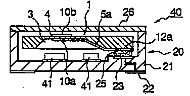
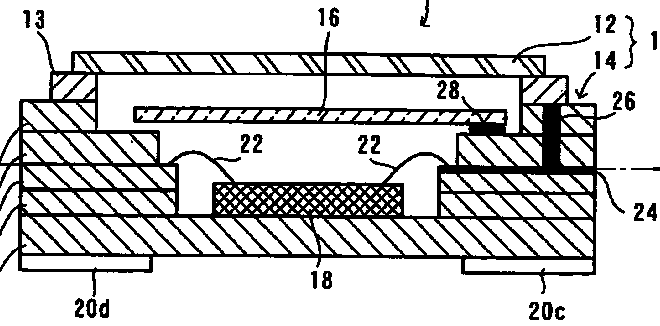
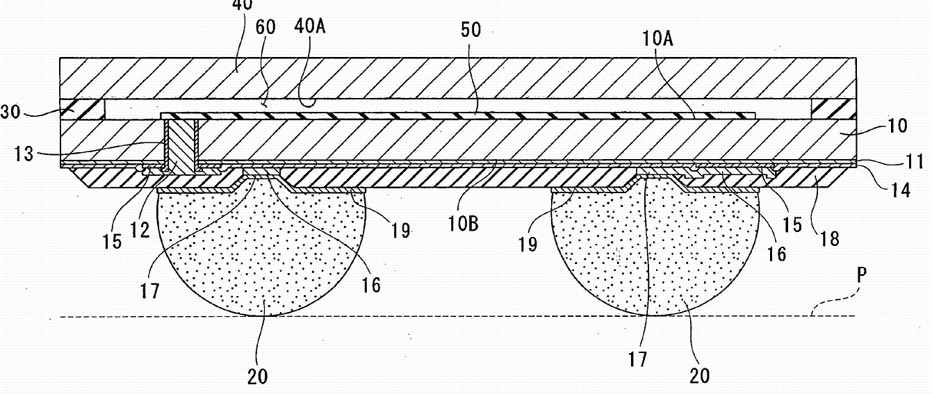
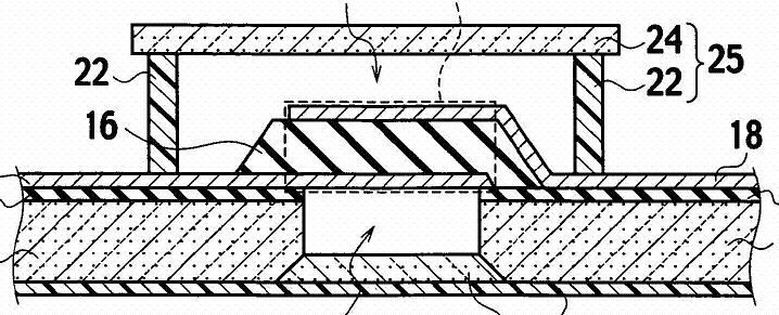
The documents classified in H03H 9/0547 relate to a vertical arrangement of the electromechanical device(s) and the other electronic component(s).
The components are disposed so as to be the one on top of the other one in a vertical plan.
For the time being, documents should be classified in H03H 9/0538 and with the keyword: 09 05b2 vertical arrangement (H03H): vertical arrangement of the electromechanical device(s) and the other electronic component(s)
EP1727275
EP0998038
US2005/093171
WO2007004137
US6087763
US2004/174092
US2005/269911
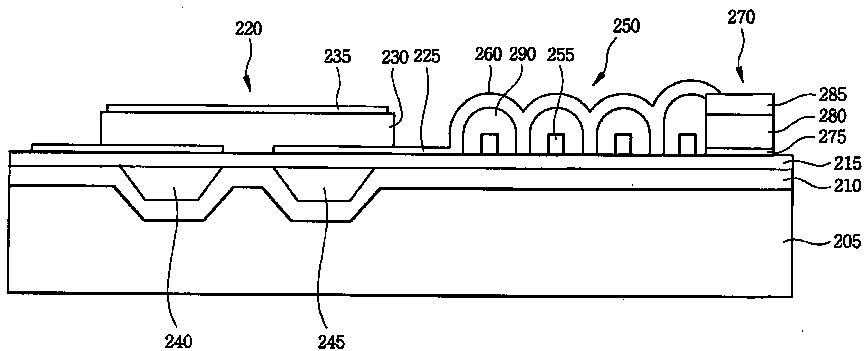
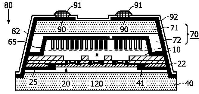
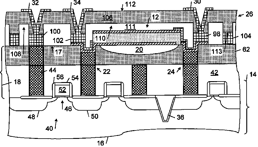
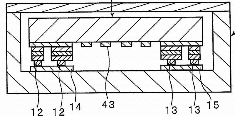
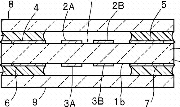
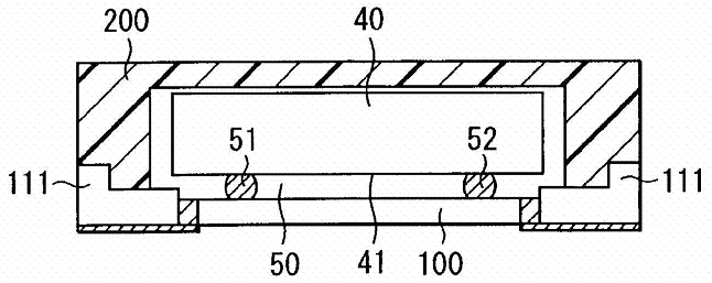
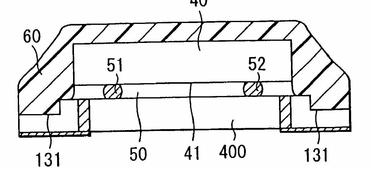
The documents classified in H03H 9/0552 relate to a vertical arrangement of the electromechanical device(s) and the other electronic component(s) wherein the different components are mounted on opposite sides of a common substrate.
For the time being, documents should be classified in H03H 9/0538 and with the keyword: 09 05b2a vertical arrangement dualface (H03H): vertical arrangement of the electromechanical device(s) and the other electronic component(s) wherein the different components are mounted on opposite sides of a common substrate
EP1612930
EP0998038
EP1689079
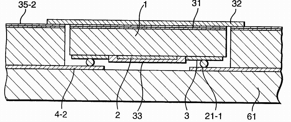
The documents classified in H03H 9/0557 relate to a vertical arrangement of the electromechanical device(s) and the other electronic component(s) wherein the other electronic component(s) are buried in the substrate.
For the time being, documents should be classified in H03H 9/0538 and with the keyword: 09 05b2b vertical arrangement buried (H03H): vertical arrangement of the electromechanical device(s) and the other electronic component(s) wherein the other electronic component(s) are buried in the substrate
US2005/230812
This document has also to be classified in H03H 9/0542
DE10060138
US2006/208833
US2006/202779
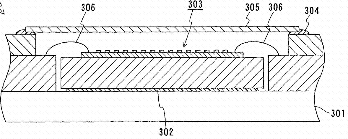
The documents classified in H03H 9/0561 relate to a vertical arrangement of the electromechanical device(s) and the other electronic component(s) wherein the whole component consists of a multilayered device.
For the time being, documents should be classified in H03H 9/0538 and with the keyword: 09 05b2c vertical arrangement multilayered (H03H): vertical arrangement of the electromechanical device(s) and the other electronic component(s) wherein the whole component consists of a multilayered device

EP0930701
US2002/005684
Note:
This technique is mostly employed for components including L or C elements.
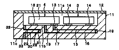
Documents relating to BAW duplexers packaging or disposal arrangements should ONLY be classified in H03H 9/706 and with the keyword (i.e. class H03H 9/0538 should not be allocated unless justified by other corresponding embodiments): 09 05b3b packaging aspects for baw duplexers (H03H)
EP1519485
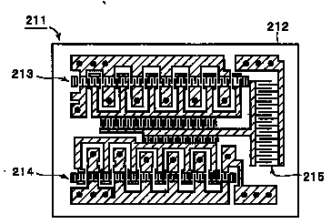
WO2005/050840 details of arrangement of parts of the duplexer on a chip part of the package
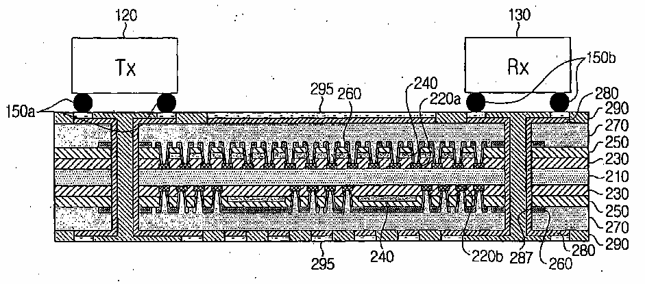
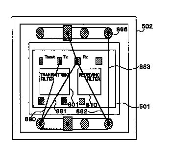
EP1508936 - Packaging aspects for BAW duplexer Note: in the doc it is also disclosed the BAW structure of Tx 120 and Rx 130
Documents relating to SAW duplexers packaging or disposal arrangements should ONLY be classified in H03H 9/706 and with the keyword (i.e. class H03H 9/0538 should not be allocated unless justified by other corresponding embodiments): 09 05b3s packaging aspects for saw duplexers (H03H)
US2004/227586
WO2005/088833
US2003/112094
US2004/116098 multilayer/exploded views of the packages are also classified
EXTRA KWs to allocate
For completeness, when relevant LC impedance matching aspects are disclosed in the document already disclosing a BAW/SAW duplexer, this one should be also classified in 09 impedance matching (H03H)
without allocating however a class in H03H 9/0004 and subgroups.
Like this, impedance matching aspects in duplexers could be easily retrieved by intersecting H03H 9/70 and subgroups class with the above mentioned KW, without overcharging the H03H 9/0004 and subgroups class.
Examples of impedance matching aspects:
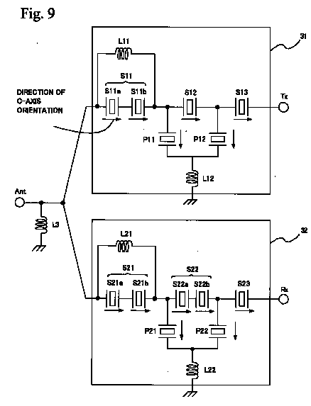
US2008055021 - Inductances L12, L22, L11, L3.
US2004/227586 capacitor 215 triggers the allocation of the present KW to this document
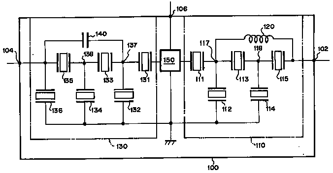
US2004130410 - Inductance 120, capacitance 140
EP1508936 - Integrating aspects for L and C

US2005046512 - Coil 7 and phase shifter 8
The documents classified in H03H 9/058 relate to holder and supporting means details for SAW devices.
If the supporting means consist of temperature regulation means, then classify also in H03H 9/08.
If the supporting means consist of elastic or damping means, then classify also in H03H 9/09.
Note: Manufacture details about holder and supporting means details should not be classified in the manufacture classes. (i.e H03H 3/00 and subgroups)
The holder and supporting means consisting of an adhesive layer.
WO 97/45955: adhesive 30
WO 2005/048449
US 2008/036094
The holder and supporting means consisting of mounting pads or bumps.
There should be either details of the mounting pads or bump or on the positioning of them on the substrate.
Almost all the SAW devices supported by bumps are flip-chip.
EP 1274167
EP 1635457
US 6222299

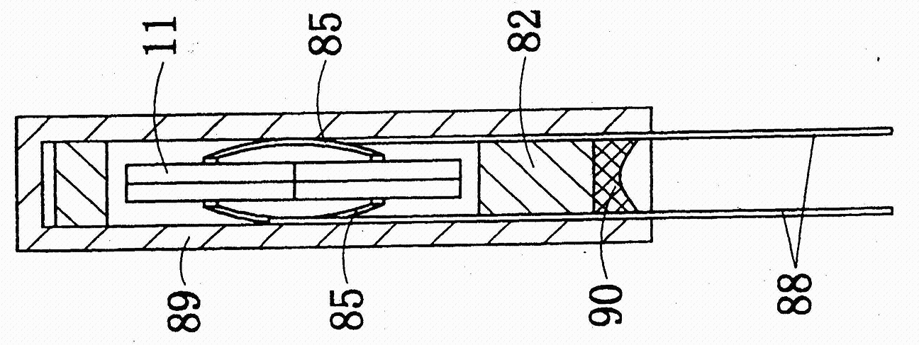
The documents classified in H03H 9/0595 relate to supporting means details for piezoelectric devices wherein the support and the resonator are formed in one body.
US 2006255691
JP 60189308
GB 1592010
JP 60070808
EP 1845616
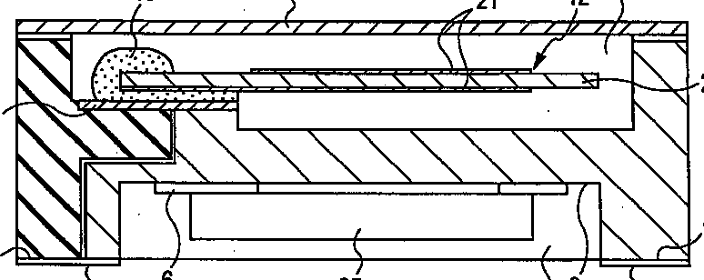
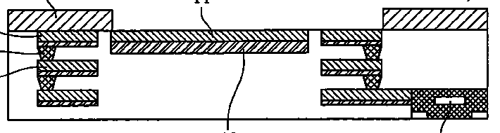
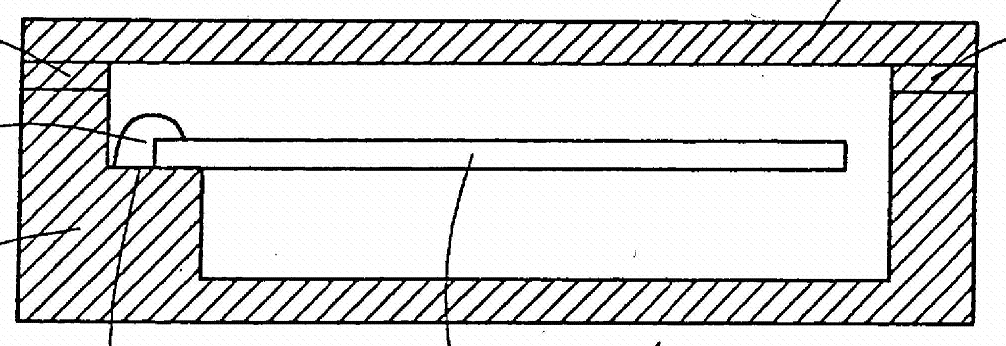
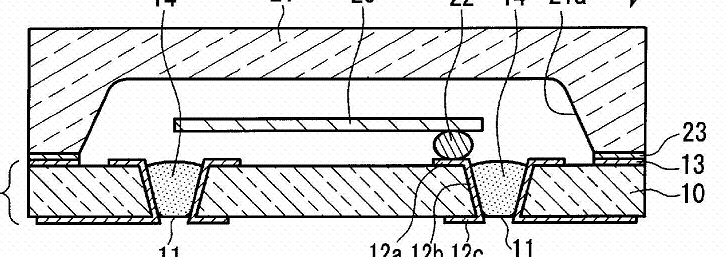
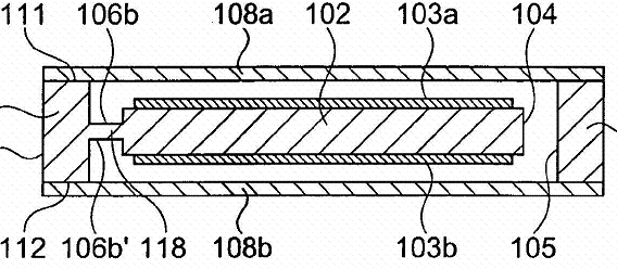
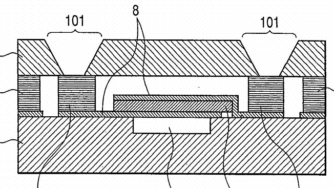
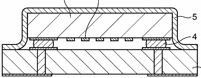
The documents classified in H03H 9/1007 relate to mounting in enclosures for BAW devices.
Note: Manufacture details about mounting in enclosures should not be classified in the manufacture classes. (i.e H03H 3/00 and subgroups)
The enclosure being defined by a frame built on a substrate and a cap, the frame having no mechanical contact with the BAW device.
(For completeness read also the definition of H03H 9/105)
WO 2008/099570
(the frame and the cap are made in a single piece)
US 2001/002807
US 2003/186673
The enclosure being defined by a frame built on a substrate and a cap, the frame having no mechanical contact with the BAW device and the BAW device is of the cantilever type.
Note: This group takes precedence over H03H 9/0519 (unless there is a lot of details about the supporting means of the cantilever).
US 2003/197566
WO 2006/114936
WO 2006/129354
JP 51134092
The enclosure being defined by a frame built on a substrate and a cap, the frame having no mechanical contact with the BAW device and the piezoelectric resonator is held between spring terminals.
DE 10035416
Spring Terminals: 85,88
DE 3148389
US 2002/003387
The enclosure being defined by two sealing substrates sandwiching the piezoelectric layer of the BAW element.
WO 2008152837: sealing substrates 5 and 7
WO 2008/102481
EP 1696561
 JP 59067710
The enclosure being defined by a housing formed by cavity in a resin.
US 3650003
EP 0978938

DE 19524881
JP 60256212
The enclosure being defined by a cover cap mounted on an element forming part of the BAW device.
The difference with H03H 9/1014 is that the cap is mounted directly on a layer (electrode, piezo) of the BAW device.

EP 1227581
DE 102007050865
WO 2008/093514
US 2007/057599
The documents classified in H03H 9/1064 relate to mounting in enclosures for SAW devices.
Note: Manufacture details about mounting in enclosures should not be classified in the manufacture classes. (i.e H03H 3/00 and subgroups)
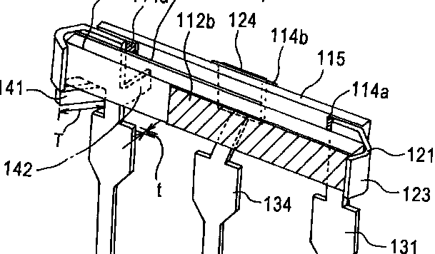
The enclosure being defined by a frame built on a substrate and a cap, the frame having no mechanical contact with the SAW device.
(For completeness read also the definition of H03H 9/1092)
US 2003/020373: frame + cap 200
GB 2334618: Cap 32
US 2002/149295
The enclosure being defined by a foil covering the non-active sides of the SAW device.
GB 2334618: Foil 32
WO 2006/106831: Foil 5
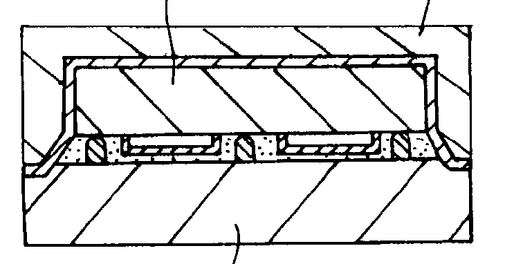
US 2003/009864
This doc is also classified in H03H 9/1085 for the sealing mass over thefoil
The enclosure being defined by a non-uniform sealing mass covering the non-active sides of the SAW device.

EP 1361657 : mass 10
WO 97/45955: mass 18
This doc is also classified in H03H 9/1078 for the foil (19)
US 2003/020373: mass 60
The enclosure being defined by a cover cap mounted on an element forming part of the SAW device on the side of the IDT's.
The difference with H03H 9/1071 is that the cap is mounted directly on the piezoelectric substrate on the side of the IDT's and not on a supporting substrate.
EP 1684423
EP 1672790
US 2001/011857
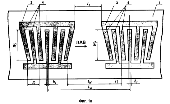
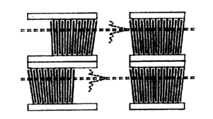
The classes H03H 9/14544+ accommodate documents disclosing "unusual/non-standard" shapes detected in the fingers or transducers for both SAW resonators and SAW filters.
Note:
Seen the relatively high degree of indentation it is wished to keep the root rather empty. It goes without saying that any document disclosing complex enough shapes which do not fall under the description of the subclasses of H03H 9/14544 are classified in the present root. It is not excluded that in the near future (testing period when only KW precursors are generated instead of real EC classes) new subclasses to appear.
Redundancies:
1) H03H 9/6426 appears to overlap the classes H03H 9/14544+. From now on, no new documents should be classified in H03H 9/6426. This class will be deleted in the future and the documents still in there will be reclassified accordingly (it is expected to move most of them in H03H 9/14544+)
Some examples:
DE102006042616
WO03038997
Notes:
1) Dog-legged fingers are to be classified under H03H 9/02637 as it is regarded as a particular case of dummy electrode structure:
EP1463200
Each finger is in split in at least two fingers
EP1115200
DE10057848
Chirped transducers present the feature of having uniformly variable distance between the fingers starting from one end till the other end of the IDT (up-chirp; down-chirp). Often the disposition of the IDTs is a plane-rotated or a diagonal one, which makes them also classifiable in H03H 9/14594 .
Chirp is necessary for compression/decompression of the waves (H03H 9/44) which makes them suitable for radar applications (G01S) or computing correlators, convolvers (G06G 7/195), for example:
US5113115 (correlator)
GB2114393 (compressor)
Broad band applications (some of the documents are still in H03H 9/14514) use also chirped structures:
JP53144646
Chirped is also used for reducing the negative effects (e.g. side lobe or ripple) of the imperfect radiation of the transducers (dispersion):
JP61032610
It should, however, hot be confounded with matched SAW devices usually used in spread spectrum coding/decoding and for which the KW
09 64m matched filters (H03H)
was created:
JP61136314
A wide band SAW filter using slanted transducer fingers has an advantage that the insertion loss is small, with respect to a SAW filter using the apodizing method or dispersion type electrodes. However, although the central pass band characteristics are adequately flat, it is generally inclined with frequency.
Some examples:
RU2171010
XP010612643
When the fan shape is a curved one, the next classification entry H03H 9/14561 and H03H 9/14564 takes precedence. For example, the following arrangement alone does not entitle the document to be classified under the present classification entry but on "Arched, Curved or Ring Shaped Transducers":
WO9710646 (incidentally, for this doc. another arrangement made it eligible, however for H03H 9/14558)
For a document to be classified in this entry it is enough to disclose a curved shape of at least one of the fingers.
Some examples:
DE102005009359
XP000208195
USRE27116E
FR2623348 (see finger 83)
US4908542
Exceptions are documents showing IDTs disposed on 3D surfaces, like (these documents are classified in the root - H03H 9/14544):
US2007241639
EP1453199
The class should contain only documents disclosing IDTs with bent asymmetrical fingers (i.e if one draws an axis in the middle of the IDT, parallel with the stretching direction of the fingers, the IDT would not be symmetric w.r.t. to that axis. For the symmetrical bent fingers H03H 9/14567 takes precedence
One of the achieved goals is reduction of TTE (triple transit echo) which makes the class close related to H03H 9/02842(1):

JP55112022
Phase coding in telecom or ID-tags is another application:
US3931597
Some other examples:
DE19943072
EP1619794
If in the fan like shape the fingers are stepped the document is to be classified here. The resultant effect is a superposition of the individual effects/radiation/excitation/frequency characteristics of the serially connected elementary IDTs (in US3727718: Fig. 3 below - 52, 53, 54, 55). Possible utilization in broad band devices is foreseen. For some applications, however, the superposition is not as important as squeezing of IDTs on the same piezoelectric surface, at the end the radiated mechanical wave being captured by individual IDTs specialized on specific bands (e.g. US3727718 below).
US3727718
Some other examples:
RU2171010
US2004108917
As the title suggests, along the finger length, the width of the finger varies (mostly stepwise).
Some examples:
EP0585863
EP1274169
the shape of the IDT gets pointed at the extreme end of the acoustic propagation track, and often one of the bus bars of the IDT is continued outside the IDT in the propagation direction and there formed in a shielding reflector with an tree like structure.
US4513262
EP0092290
JP59125113

EP0103932
The present sub-class accommodates documents disclosing relevant aspects concerning the last finger-electrodes of IDTs, and namely IDTs having only the last finger-electrodes different from the remaining fingers in the IDTs.
The document, anyhow, would receive a class in H03H 9/64+ or H03H 9/0028+ if the filter structure is of importance (i.e. not trivial).
The present sub-class accommodates documents disclosing relevant aspects concerning the last finger-electrodes of IDTs, and namely IDTs having only the last finger-electrodes of a special different from the rest of the IDT fingers.
The document, anyhow, would receive a class in H03H 9/64+ or H03H 9/0028+ if the filter structure is of importance (i.e. not trivial).
EP2066026
EP0088400
US2007024397
The present sub-class accommodates documents disclosing relevant aspects concerning the last finger-electrodes of IDTs, and namely IDTs having only the last finger-electrodes split.
The document, anyhow, would receive a class in H03H 9/64+ or H03H 9/0028+ if the filter structure is of importance (i.e. not trivial).
EP1175006
WO0039925
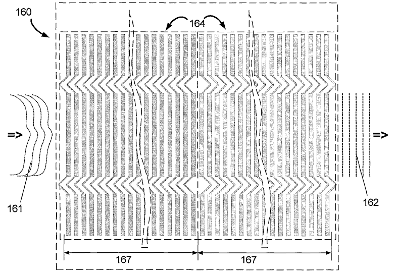
One of the IDTs in the filter is split into two longitudinally coupled electrically connected IDTs in order to cope with necessary impedance match (mostly used in balun devices).
WO2007049754
One of the IDTs in the filter is split into two stack like arranged IDTs in order to cope with necessary impedance match (mostly used in balun devices).
GB2387495
Basically this geometrical shape was adopted in order to increase the efficiency of the SAW filters by reducing the insertion loss. As a bonus, the ripple is also reduced. Some applicants bring as an (additionally) solved problem the compensation of the variation with the temperature of the frequency characteristics (e.g. US4379274).
Phenomena: Piezoelectric substrates have anisotropic characteristics, and the excitation efficiency is negatively affected by the propagation direction of the surface acoustic wave. As shown in US2007046394, the excitation efficiency is reduced by the deviation (dispersion) of the propagation direction of the surface acoustic wave from the direction perpendicular to the fingers.
As a consequence the output IDTs do not to "catch" all the SAWs emitted by the input ones and the insertion loss increases.
As a solution a plane rotated IDT (somehow one side slanted as in the figure below) brings an improvement by increasing the "amount" of the received waves.
Some examples:
US6373353
EP1542361 - plane rotated IDT/resonator.
The documents classified in H03H 9/17 relate to single resonators consisting of piezoelectric or electrostrictive material.
A resonator is a one port device having two terminals, whereas a filter is a device having at least two ports.
For example, this is a resonator:
but this is a filter:
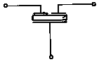
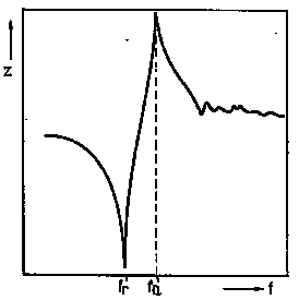
A resonator presents a frequency response like this:
fr being the resonance frequency and fa the anti-resonance frequency.
Details of bulk acoustic wave devices (e.g. vibration mode, dimensional parameters, characteristics of piezoelectric layers, treatment of substrate, compensation of undesired effects) are classified in H03H 9/02007+.
Piezoelectric resonators implemented with thin-film techniques are classified in H03H 9/171+.
Piezoelectric resonators comprising a ceramic piezoelectric layer are classified in H03H 9/176.
Piezoelectric resonators of the energy-trap type are classified in H03H 9/177.
Piezoelectric resonators comprising a laminated structure of multiple piezoelectric layers with inner electrodes are classified in H03H 9/178.
Note:
There are no documents classified in H03H 9/15 as there is no use of this class for the moment.
There are various resonator structures which are classified in H03H 9/17, as for example:
- Cantilever Resonators:

These documents should be provided with the following keyword:
09 baw cantilever resonators (H03H)
- Lateral Field Resonators:
In lateral-field excitation resonators a single pair of electrode is formed on a surface of the piezoelectric plate. The electrodes are separated by a narrow gap across which is generated an electric driving field by the application of an excitation voltage applied to the electrode extremities at the peripheral edge of the piezoelectric plate.
- And a lot of other types:

The documents classified in H03H 9/171 relate to resonators implemented with thin-film techniques presenting a structure which comprises no means for mounting on a substrate (see H03H 9/172+).
The group contains a lot of different resonator structures implemented with thin-film techniques, as for example:
The documents classified in H03H 9/172 relate to resonators implemented with thin-film techniques with emphasis on the means for mounting on a substrate.
There are a lot of possibilities for mounting a thin-film resonator on a substrate, different from the one associated to the air-gap type (see H03H 9/173), the membrane type (see H03H 9/174) and the acoustic mirror type (see H03H 9/175), as for example:
- Suspended thin film resonators (STFR) or resonators having a bridge structure:
- Most of the microelectromechanical resonators (MEMS) comprising a piezoelectric layer:

For more details about piezoelectric mems, see Note on FBAR versus MEMS.
- Overmoded resonators (see also H03H 9/02007):
- And a lot of other resonators:

Note:
The last figure has also to be classified in the keyword 09 baw cantilever resonators (H03H).
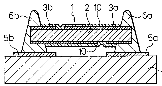
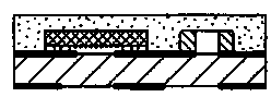
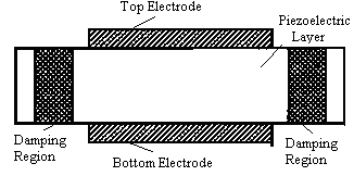
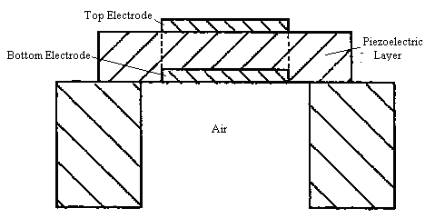
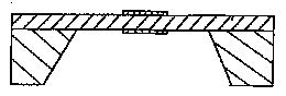
The documents classified in H03H 9/173 relate to air-gap type resonators.
In the air-gap type resonators, there is a cavity formed between the resonant part and the substrate.
This cavity is often formed by etching a sacrificial layer (also called temporary layer).
Forming a cavity under the resonant portion is one way of confining the bulk acoustic waves to a volume usually comprised between the overlapping area of the electrodes, i.e. of providing the required acoustical isolation between the resonant structure and the supporting substrate.
It has to be noted that structures with the cavity inside the substrate have also to be classified in H03H 9/173, as for example:

Note:
If details about membrane and/or mirror type resonators are provided, the document should also be classified in H03H 9/174 and/or H03H 9/175.
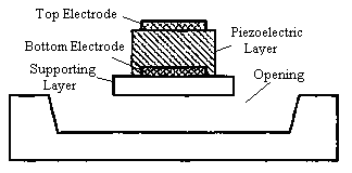
The documents classified in H03H 9/174 relate to membrane type resonators.
In the membrane type resonators, there is a cavity (a via hole) formed under the resonant part through the substrate.
Forming a cavity under the resonant portion is one way of confining the bulk acoustic waves to a volume usually comprised between the overlapping area of the electrodes, i.e. of providing the required acoustical isolation between the resonant structure and the supporting substrate.
There are two main types of membrane resonators (both classified in H03H 9/171).
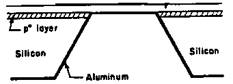
1/ Edge supported membrane resonators:
The resonating structure comprises, in the cavity area, a piezoelectric layer which is supported on the substrate by its edges.
These membrane resonators are further characterized by a direct interface bottom electrode / air.
2/ Composite membrane resonators:
The resonating structure comprises, in the cavity area, a piezoelectric layer which is supported on a non-piezoelectric layer (e.g. a semiconductor or dielectric layer).
These documents should be provided with the following keyword:
09 17a1b composite membrane (H03H)
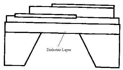
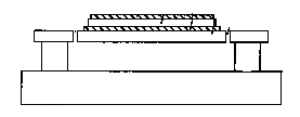
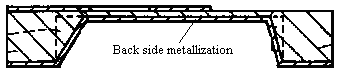
A last detail applicable to the two types of membrane resonator is the bottom side metallization.
The metallization forming the bottom electrode of the resonator completely covers the bottom surface of the membrane in the cavity area, and extends in a seamless way so as to cover also the adjacent walls of the substrate defining the cavity.
These documents should be provided with the following keyword:
09 13 bottom side metallization (H03H)
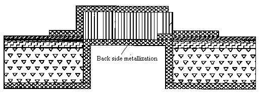
The last figure represents a composite membrane resonator with the bottom side metalization. So it has to be classified in H03H 9/174 and under the two keywords described before.
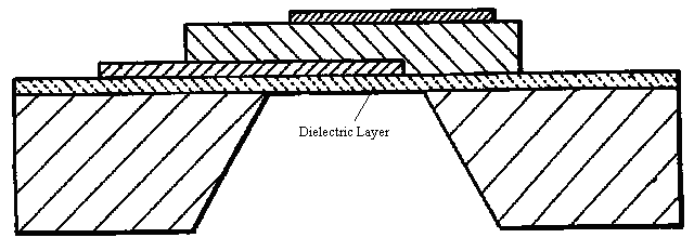
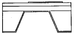
This last membrane resonator presents a bottom side metallization but is not a composite membrane resonator, as the dielectric layer is not present in the resonant part.
Note:
If details about air-gap and/or mirror type resonators are provided, the document should also be classified in H03H 9/173 and/or H03H 9/175.
The documents classified in H03H 9/175 relate to mirror type resonators (aka solidly mounted resonators).
In the mirror type resonators, there is an acoustic reflector (aka acoustic mirror, Bragg reflector...) composed of alternatively arranged high and low acoustic impedance layers. Usually the thickness of these layers is λ/4 or λ/2. The acoustic reflector is disposed between the resonant part and the substrate.
Forming an acoustic reflector under the resonant portion is one way of confining the bulk acoustic waves to a volume usually comprised between the overlapping area of the electrodes, i.e. of providing the required acoustical isolation between the resonant structure and the supporting substrate.

If he alternating laminated layers of high and low acoustic impedance are disposed on top of the top electrode, the document should not be classified in H03H 9/175 but accordingly to the other characteristics of the structure of the resonator, as for example:

Note:
If details about air-gap and/or membrane type resonators are provided, the document should also be classified in H03H 9/173 and/or H03H 9/174.
The documents classified in H03H 9/176 relate to single resonators comprising a ceramic piezoelectric layer, which is polarized.
This polarization is required in order to exploit the specific piezoelectric properties of the ceramic piezoelectric layer.
Note:
H03H 9/177 and H03H 9/178 take precedence over H03H 9/176.
There are two groups of ceramic materials:
* Non spontaneous polarized materials:
Ta2O5, (Ba,Sr)TiO3 (BST), LiTaO3 (lithium tantalate), LiNbO3 (lithium niobate), AlN (aluminium nitride)
* Spontaneous polarized materials:
Ferroelectric:
Ferroelectrics exhibit a spontaneous dipole moment which can be reoriented.
Pb(Zr,Ti)O3 (PZT, lead zirconate, lead titanate), SrBi2Ta2O9(SBT), perovskite type.
Antiferroelectric:
Antiferroelectrics have antiparallel dipoles which can be transferred into a parallel state (ferroelectric state) under an applied field. As a consequence, antiferroelectrics exhibit a double hysteresis loop in their P-E curve.
Pb0.99Nb0.02(Zr0.85 Sn0.13 Ti0.02)0.98O3 (PNZST), Pb0.97La0.02(Zr0.65 Sn0.31 Ti0.04)O3 (PLZST, PLZT).
The documemts classified in H03H 9/176 disclose resonators comprising:
- Non spontaneous polarized materials being polarized.
- Spontaneous polarized materials taking advantage of the intrinsic piezoelectric properties of these materials, wherein in some cases, the direction of the polarization will be reoriented.
Also if the ceramic piezoelectric layer comprises a plurality of stacked piezoelectric layers, with no embedded electrodes, as for example:
Documents dealing with the properties of the ceramic piezoelectric layer (e.g. cutting angles) are classified in H03H 9/02031.
The documents classified in H03H 9/177 relate to energy-trap type resonators.
Note:
As most of the time the substrates of the energy-trap type resonators are made of ceramic, H03H 9/177 takes precedence on H03H 9/176.
This type of resonator is constituted of a piezoelectric layer and a pair of electrodes formed on opposite surfaces of the piezoelectric layer.
The vibration energy is produced and mainly confined to the volume determined in the piezoelectric layer by the overlapping area of the electrodes. However, it can not be avoided that this energy propagates outside this virtual volume, resulting in an increase of the insertion loss (see last figure).


In the last figure, the vibrating part is at the center, and then we have reflective layers and holding members.
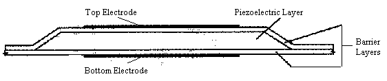
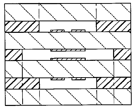
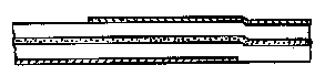
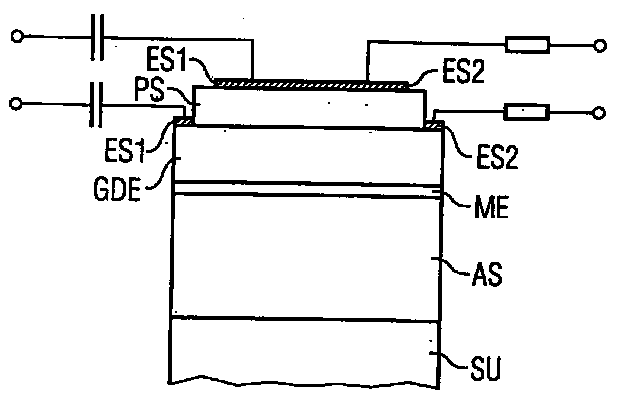
Documents classified in H03H 9/178 relate to single resonators comprising a laminated structure of multiple piezoelectric layers with inner electrodes.
Note:
H03H 9/178 takes precedence over H03H 9/176.
The electrode layers and the piezoelectric layers, which are made of ceramic materials are alternately stacked. (see definition of H03H 9/176 for more details about ceramic materials)
The stacked piezoelectric layers are interleaved with electrodes. Any two adjacent layers have opposite polarities.
There are two main groups of resonators of this type.
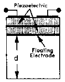
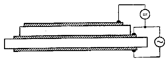
1/ In the first group, the electrodes are alternately connected to two different external bus-bars electrodes.
2/ In the second group, each adjacent pair of piezoelectric layers sandwiches a floating electrode entirely embedded in the multilayer structure.
There are also some other resonators not falling under the two previous group, which have still to be classified in H03H 9/178 as they also comprised two piezoelectric layers made of ceramic material and inner electrodes.

Details about a ladder or lattice structure of resonators of this type are classified respectively in H03H 9/568, H03H 9/605 and H03H 9/0095.
Filters of the laminated structure are classified in H03H 9/562 or in H03H 9/581.
The documents classified in H03H 9/54 relate to filters comprising resonators consisting of piezoelectric or electrostrictive material, which are not of the surface acoustic waves type, since H03H 9/64 takes precedence.
A filter is a device having at least two ports, whereas a resonator is a one port device having two terminals.
For example, this is a filter:
but this is a resonator:
Filters comprising piezoelectric resonator(s) and passive elements are classified in H03H 9/542.
Filters comprising piezoelectric resonator(s) and active elements are classified in H03H 9/545.
Piezoelectric monolithic filters are classified in H03H 9/56+.
Piezoelectric polylithic filters are classified in H03H 9/58+.
Details of bulk acoustic wave devices (e.g. vibration mode, dimensional parameters, characteristics of piezoelectric layers, treatment of substrate, compensation of undesired effects) are classified in H03H 9/02007+.
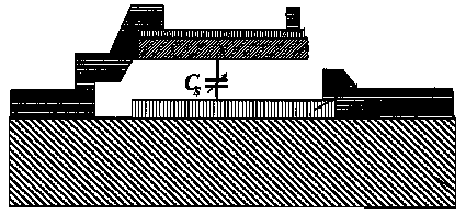
The documents classified in H03H 9/542 relate to filters comprising piezoelectric resonator(s) and passive elements (R, L, C).
Note:
H03H 9/545 takes precedence over H03H 9/542.
There are various possibilities:


Note:
The last figure has also to be classified in H03H 9/0095.
Note:
If the passive elements are only coupling capacitances, as for example:

Then the documents should not be classified in H03H 9/542, but in H03H 9/56 or H03H 9/58 depending if the structure is monolithic or polylithic.
The documents classified in H03H 9/545 relate to filters comprising piezoelectric resonator(s) and active elements.
Note:
H03H 9/545 takes precedence over H03H 9/542.
There are various possibilities:
Note:
Oscillators using amplifier with the frequency-determining element being an acoustic wave piezoelectric resonator are classified in H03B 5/326, as for example:
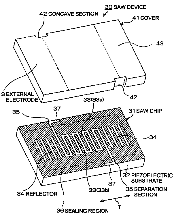
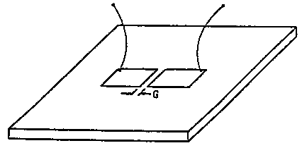
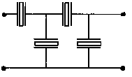
The documents classified in H03H 9/56 relate to monolithic crystal filters consisting of piezoelectric or electrostrictive material.
Monolithic filters comprise a single piezoelectric layer sandwiched between at least three electrodes, so as to form at least two resonators.
To be classified in H03H 9/56 and lower, details about the structure of the piezoelectric filter should be given.
![]()
![]()
Monolithic filters comprising a ceramic piezoelectric layer are classified in H03H 9/562.
Monolithic filters implemented with thin-film techniques are classified in H03H 9/564.
Monolithic filters including details of electrical coupling means are classified in H03H 9/566 or H03H 9/568 if the electrical coupling means are arranged in order to form a ladder configuration.
The documents classified in H03H 9/562 relate to monolithic filters comprising a ceramic piezoelectric layer, which is polarized.
This polarization is required in order to exploit the specific piezoelectric properties of the ceramic piezoelectric layer.
There are two groups of ceramic materials:
* Non spontaneous polarized materials:
Ta2O5, (Ba,Sr)TiO3 (BST), LiTaO3 (lithium tantalate), LiNbO3 (lithium niobate), AlN (aluminium nitride)
* Spontaneous polarized materials:
Ferroelectric:
Ferroelectrics exhibit a spontaneous dipole moment which can be reoriented.
Pb(Zr,Ti)O3 (PZT, lead zirconate, lead titanate), SrBi2Ta2O9(SBT), perovskite type.
Antiferroelectric:
Antiferroelectrics have antiparallel dipoles which can be transferred into a parallel state (ferroelectric state) under an applied field. As a consequence, antiferroelectrics exhibit a double hysteresis loop in their P-E curve.
Pb0.99Nb0.02(Zr0.85 Sn0.13 Ti0.02)0.98O3 (PNZST), Pb0.97La0.02(Zr0.65 Sn0.31 Ti0.04)O3 (PLZST, PLZT).
The documents classified in H03H 9/562 disclose monolithic filters comprising:
- Non spontaneous polarized ceramic materials being polarized.
- Spontaneous polarized ceramic materials taking advantage of the intrinsic piezoelectric properties of these materials, wherein in some cases, the direction of the polarization will be reoriented.
Ceramic monolithic filters with a laminated structure like the one of the resonators of H03H 9/178 are classified in H03H 9/562, as for example:
Documents dealing with the properties of the ceramic piezoelectric layer (e.g. cutting angles) are classified in H03H 9/02031.
The documents classified in H03H 9/564 relate to monolithic filters implemented with thin-film techniques.
Most of them disclose details related to mounting on a substrate (see H03H 9/172+ for more details about the known structure types), as for example:
- Air-gap type:
- Membrane type:
- Mirror type:
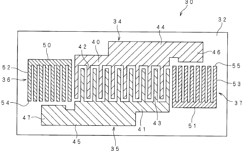
The documents classified in H03H 9/566 relate to monolithic filters including details of electrical coupling means.
The electrical coupling means are understood as means interconnecting the electrodes of the piezoelectric monolithic filter. Coupling capacitances are not understood as electrical coupling means (see example at the bottom of the page).
Note:
H03H 9/0095 takes precedence over H03H 9/566.
The electrical coupling means can be implemented in a variety of ways:
Electrical coupling means arranged in order to form a ladder configuration are classified in H03H 9/568.
Electrical coupling means arranged in order to form a BALUN network are classified in H03H 9/0095.
Note:
If the coupling means are only coupling capacitances, as for example:
Then the documents should not be classified in H03H 9/566, but in H03H 9/56.
The documents classified in H03H 9/568 relate to monolithic filters including details of electrical coupling means arranged in order to form a ladder configuration.
A ladder configuration is of this type:
Only documents disclosing specific details about the ladder are classified in H03H 9/568.
Note:
If the ladder filter is not a monolithic filter (see the definition in H03H 9/56), see H03H 9/605.
The documents classified in H03H 9/58 relate to multiple crystal filters (aka polylithic crystal filters) consisting of piezoelectric or electrostrictive material.
Polylithic filters comprise multiple piezoelectric layers, each sandwiched between electrodes.
To be classified in H03H 9/58 and lower, details about the structure of the piezoelectric filter should be given.
Polylithic filters comprising ceramic piezoelectric layers are classified in H03H 9/581.
Polylithic filters implemented with thin-film techniques are classified in H03H 9/582+.
Polylithic filters comprising electrical coupling means are classified in H03H 9/60 or in H03H 9/605 if the electrical coupling means are arranged in order to form a ladder configuration.
The documents classified in H03H 9/581 relate to polylithic filters comprising ceramic piezoelectric layers, which are polarized.
These polarizations are required in order to exploit the specific piezoelectric properties of the ceramic piezoelectric layers.
There are two groups of ceramic materials:
* Non spontaneous polarized materials:
Ta2O5, (Ba,Sr)TiO3 (BST), LiTaO3 (lithium tantalate), LiNbO3 (lithium niobate), AlN (aluminium nitride)
* Spontaneous polarized materials:
Ferroelectric:
Ferroelectrics exhibit a spontaneous dipole moment which can be reoriented.
Pb(Zr,Ti)O3 (PZT, lead zirconate, lead titanate), SrBi2Ta2O9(SBT), perovskite type.
Antiferroelectric:
Antiferroelectrics have antiparallel dipoles which can be transferred into a parallel state (ferroelectric state) under an applied field. As a consequence, antiferroelectrics exhibit a double hysteresis loop in their P-E curve.
Pb0.99Nb0.02(Zr0.85 Sn0.13 Ti0.02)0.98O3 (PNZST), Pb0.97La0.02(Zr0.65 Sn0.31 Ti0.04)O3 (PLZST, PLZT).
The documents classified in H03H 9/581 disclose polylithic filters comprising:
- Non spontaneous polarized ceramic materials being polarized.
- Spontaneous polarized ceramic materials taking advantage of the intrinsic piezoelectric properties of these materials, wherein in some cases, the direction of the polarization will be reoriented.
Ceramic polylithic filters with a laminated structure corresponding to the one of the resonators of H03H 9/178 are classified in H03H 9/581, as for example:
Documents dealing with the properties of the ceramic piezoelectric layer (e.g. cutting angles) are classified in H03H 9/02031.
The documents classified in H03H 9/582 relate to polylithic filters implemented with thin-film techniques.
There are various possibilities:
Means of acoustical coupling between the piezoelectric layers are classified in H03H 9/583+.
Means for mounting on a substrate are classified in H03H 9/586+.
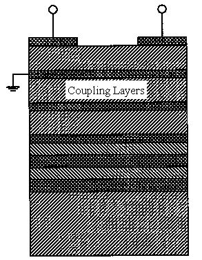
The documents classified in H03H 9/583 relate to thin-film polylithic filters with emphasis on the means of acoustical coupling.
Documents having unusual acoustical coupling details, not corresponding to the definitions of the coupled resonator filter (H03H 9/584) or the stacked crystal filter (H03H 9/585), are classified in H03H 9/583.
There are various possibilities:
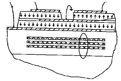
The documents classified in H03H 9/584 relate to thin-film polylithic filters comprising stacked piezoelectric layers acoustically coupled through acoustic coupling layers.
A coupled resonator filter (CRF) comprises two or more stacked piezoelectric resonators (consisting each of a piezoelectric layer sandwiched between two electrodes) that are coupled by an acoustic coupling layer located between the piezoelectric resonators.

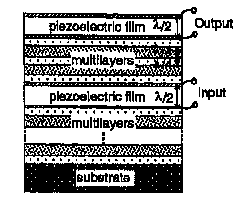
Sometimes these filters are called HBAR for High-overtone Bulk Acoustic Resonator.
These filters are of the overmoded type and should also be classified in H03H 9/02015 and provided with the keyword 09 02b baw details vibration mode overmoded (H03H), as for example:
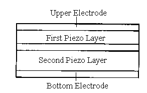
The documents classified in H03H 9/585 relate to thin-film polylithic filters comprising stacked piezoelectric layers acoustically coupled according to the stacked type.
A stacked crystal filter (SCF) comprises a first piezoelectric layer sandwiched between a top electrode and an intermediate electrode, and a second piezoelectric layer sandwiched between the intermediate electrode and a bottom electrode. Most of the time, the intermediate electrode is grounded.
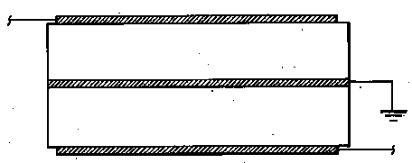
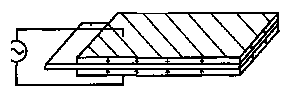

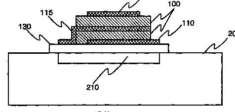
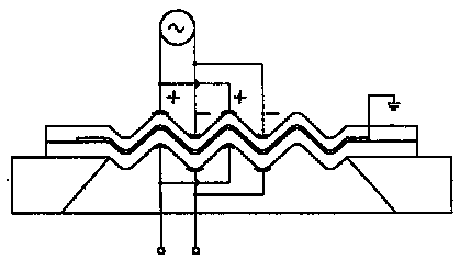
Sometimes these filters are called HBAR for High-overtone Bulk Acoustic Resonator.
These filters are of the overmoded type and should also be classified in H03H 9/02015 and provided with the keyword 09 02b baw details vibration mode overmoded (H03H), as for example:
Note:
Resonators that comprise three electrodes and two piezoelectric layers, but where the electrodes are connected so that the device behaves as a resonator and not as a filter, having quite the same structure as Stacked Crystal Filter should be classified in H03H 9/178, as for example:
In case there are no electrodes between the at least two piezoelectric layers, then the document should not be classified here, but in the resonator classes (H03H 9/17+), as for example:
The documents classified in H03H 9/586 relate to polylithic filters implemented with thin-film techniques with emphasis on the means for mounting on a substrate.
Polylithic filters with means for mounting on a substrate, which are different from the one associated to the air-gap type (see H03H 9/587), the membrane type (see H03H 9/588) and the acoustic mirror type (see H03H 9/589) are classified in H03H 9/586, as for example:
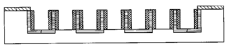
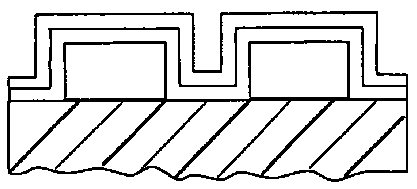
Documents comprising a mix of the known types have also to be classified in H03H 9/586, as for example:
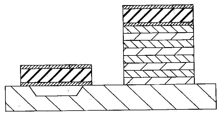
The documents classified in H03H 9/587 relate to thin-film polylithic filters of the air-gap type.
In the air-gap type thin-film polylithic filters, there are one or more cavities formed between the resonant part and the substrate.
The cavities are often formed by etching a sacrificial layer (also called temporary layer).
Forming a cavity under the resonant portion is one way of confining the bulk acoustic waves to a volume usually comprised between the overlapping area of the electrodes, i.e. of providing the required acoustical isolation between the resonant structure and the supporting substrate.
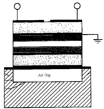
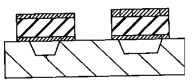
The documents classified in H03H 9/588 relate to thin-film polylithic filters of the membrane type.
In the membrane type thin-film polylithic filters, there are one or more cavities (via holes) formed under the resonant part through the substrate.
Forming a cavity under the resonant portion is one way of confining the bulk acoustic waves to a volume usually comprised between the overlapping area of the electrodes, i.e. of providing the required acoustical isolation between the resonant structure and the supporting substrate.
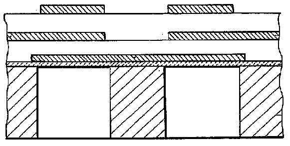
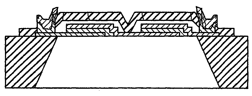
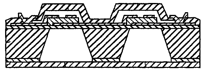
The documents classified in H03H 9/589 relate to thin-film polylithic filters of the mirror type.
In the mirror type thin-film polylithic filters, there are one or more acoustic reflectors (aka acoustic mirrors, Bragg reflectors...) composed of alternatively arranged high and low acoustic impedance layers. Usually the thickness of these layers is λ/4 or λ/2. The acoustic reflectors are disposed between the resonant part and the substrate.
Forming an acoustic reflector under the resonant portion is one way of confining the bulk acoustic waves to a volume usually comprised between the overlapping area of the electrodes, i.e. of providing the required acoustical isolation between the resonant structure and the supporting substrate.
Note:
Acoustic reflectors can also be placed on top of the resonators. This is mostly done in relation with encapsulation.
The documents classified in H03H 9/60 relate to polylithic filters including details of electrical coupling means.
The electrical coupling means are understood as means interconnecting the electrodes of the piezoelectric elements. Coupling capacitances are not understood as electrical coupling means (see example at the end of the class description).
Note:
H03H 9/0095 takes precedence over H03H 9/60.
The electrical coupling means can be implemented in a variety of ways:

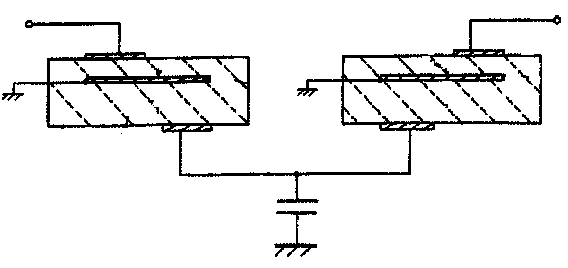
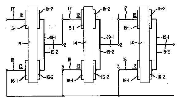
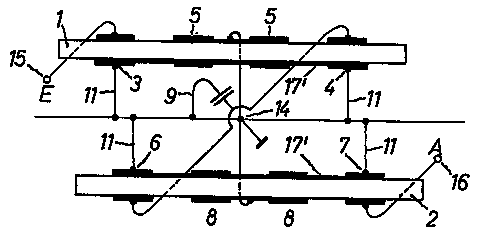
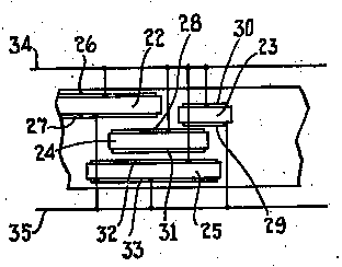
Electrical coupling means arranged in order to form a ladder configuration are classified in H03H 9/605.
Electrical coupling means arranged in order to form a BALUN network are classified in H03H 9/0095.
Note:
If the coupling means are only coupling capacitances, as for example:
The documents classified in H03H 9/605 relate to polylithic filters including details of electrical coupling means arranged in order to form a ladder configuration.
A ladder configuration is of this type:
Only documents disclosing specific details about the ladder can be found in H03H 9/605, as for examples:

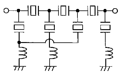
Note:
If the ladder filter is not a polylithic filter (see the definition in H03H 9/58), see H03H 9/568.
Note:
Duplexers disclosing an emitter and a receiver filter comprising multiple resonators connected in a ladder configuration, without details given on the ladder are classified in H03H 9/706, as for example:
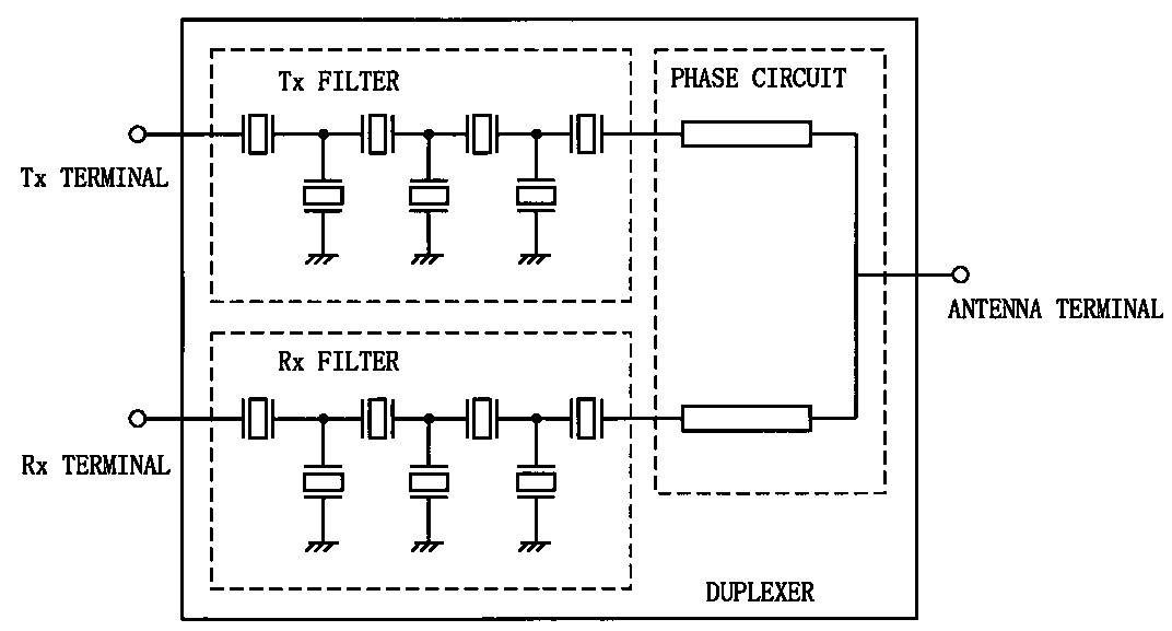
Any document disclosing SAW coupled resonator filters not falling under the scope of the subclasses depending on H03H 9/6433 or presenting a precedence to H03H 9/6433 is to be classified here (i.e. SAW coupled filters having more than 2 acoustic tracks; multi-track filters comprising parallel in/out electrically connected filters, etc.). Some examples are given below in the figures.

Fig. 1
Relationship BALUN devices (H03H 9/0028) - coupled resonator filters (H03H 9/6433)
BALUN aspects/embodiments are only to be classified in H03H 9/0028+ although most of the times BALUN devices employ SAW coupled structures. This is already specified by the precedence relationship defined in the title of the class H03H 9/6433.
However, documents disclosing also other embodiments exclusively falling under the scope of H03H 9/6433+, except those embodiments concerning BALUN aspects, are also to be classified in H03H 9/6433+ accordingly.
Completeness in search:
For completeness H03H 9/1455, H03H 9/64+ have to be consulted. Further reorganisation is foreseen in future in order to avoid this supplementary work.
Note:
For general remarks concerning SAW coupled resonator filters refer to the description of class H03H 9/6433 in the Definition Editor.
In the present class (H03H 9/6436) are classified documents having only one acoustic track.
Some examples are to be found here below:
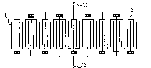
Fig. 1
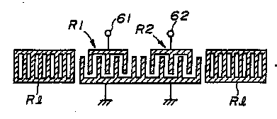
Fig. 2
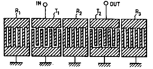
Fig. 3
Filtering structures like the one in Fig. 4 containing series connected resonators like (5a+4a+5b) and (7a+6a+7b) are also to be classified in H03H 9/6436. The problem solved by the series resonators is most of the time one of improving the steepness of the transition band of the filter. For this purpose the series resonators have to be designed with the resonance frequency having a value which coincides with the beginning of the transition band and the end of the 3dB portion of the pass band.
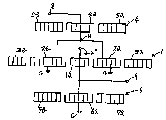
Fig. 4
For general remarks concerning SAW coupled resonator filters refer to the description of class H03H 9/6433 in the Definition Editor.
In the present class (H03H 9/6443) are classified documents disclosing two acoustic tracks which are acoustically coupled.
An example is to be found here below:
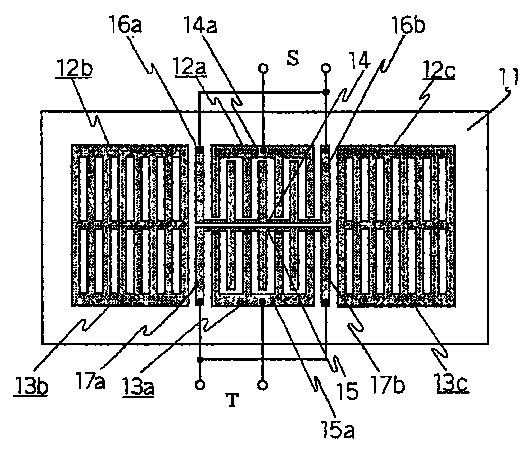
Fig. 1
Note:
For general remarks concerning SAW coupled resonator filters refer to the description of class H03H 9/6433 in the Definition Editor.
In the present class (H03H 9/6446) are classified documents having:
a) two acoustic tracks performing the filtering; and
b) the two tracks are acoustically coupled via floating multistrip lines (aka strip lines).
Some examples are to be found here below:
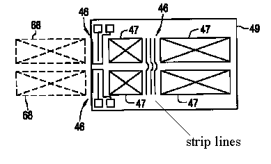
Fig. 1
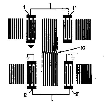
Fig. 2
For general remarks concerning SAW coupled resonator filters refer to the description of class H03H 9/6433 in the Definition Editor.
In the present class (H03H 9/645) are classified documents having:
a) two acoustic tracks performing the filtering; and
b) the two tracks are acoustically coupled via grating reflector(s) overlapping both acoustic tracks.
Some examples are to be found here below:
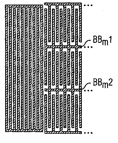
Fig. 1
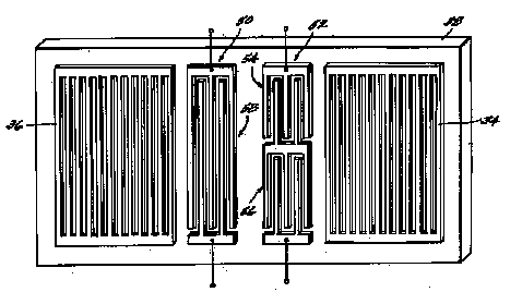
Note:
For general remarks concerning SAW coupled resonator filters refer to the description of class H03H 9/6433 in the Definition Editor.
In the present class (H03H 9/6453) are classified documents having:
a) two acoustic tracks performing the filtering; and
b) the two tracks are acoustically coupled via at least one IDT overlapping both acoustic tracks.
Some examples are to be found here below:
Fig. 1
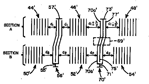
Fig. 2
For general remarks concerning SAW coupled resonator filters refer to the description of class H03H 9/6433 in the Definition Editor.
In the present class (H03H 9/6459) are classified documents having:
a) two acoustic tracks performing the filtering; and
b) the two tracks are electrically coupled via only one connecting electrode (transmission line).
Some examples are to be found here below:
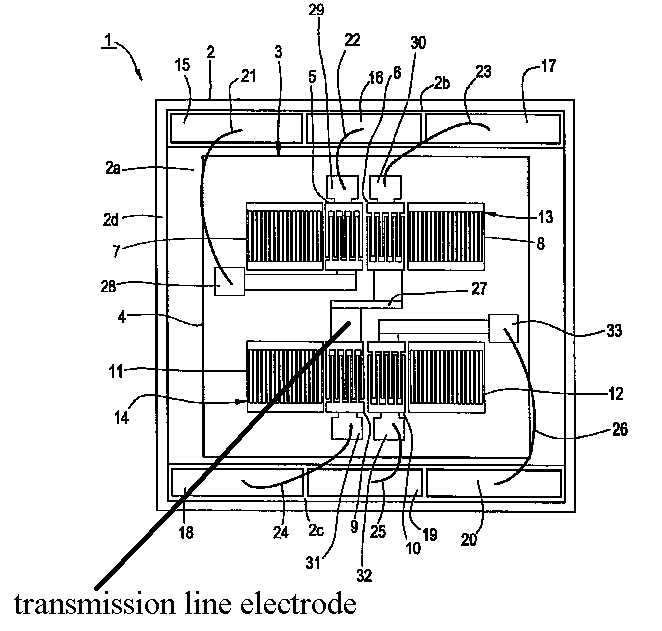
Fig. 1
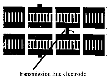
Fig. 2
NOTE
When the transmission line electrode is the whole bus bar electrode like in the figure below, H03H 9/6463 takes precedence.
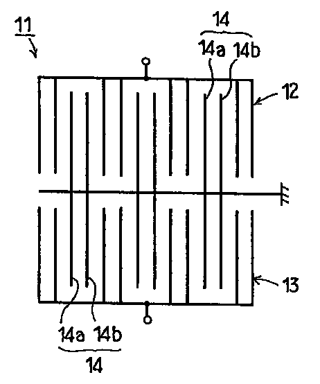
Fig. 3
For general remarks concerning SAW coupled resonator filters refer to the description of class H03H 9/6433 in the Definition Editor.
In the present class (H03H 9/6463) are classified documents having:
a) two acoustic tracks performing the filtering; and
b) the two tracks are electrically coupled via a whole bus bar used for the two comb electrodes adjacently placed in the acoustic tracks.
Some examples are to be found here below:
Fig. 1
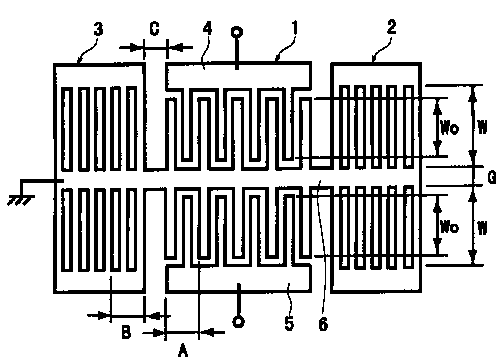
Fig. 2
For general remarks concerning SAW coupled resonator filters refer to the description of class H03H 9/6433 in the Definition Editor.
In the present class (H03H 9/6466) are classified documents having:
a) two acoustic tracks performing the filtering;
b) each acoustic track comprises at least 3 IDTs; and
c) the two tracks are electrically coupled via one transmission line electrode which can be split and which connects one IDT from the upper track with at least one IDT from the lower track.
Some examples are to be found here below:
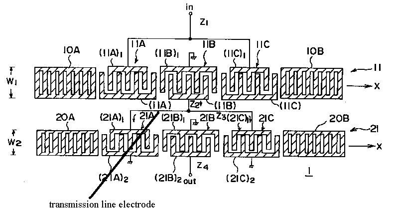
Fig. 1
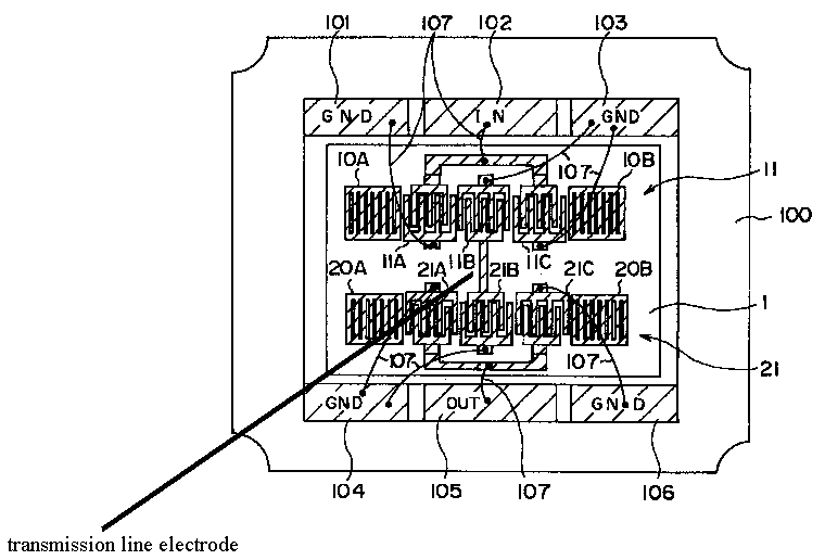
Fig. 2
For general remarks concerning SAW coupled resonator filters refer to the description of class H03H 9/6433 in the Definition Editor.
In the present class (H03H 9/6469) are classified documents having:
a) two acoustic tracks performing the filtering; and
b) the two tracks are electrically coupled via two, electrically separated transmission line electrodes which connect two pairs of IDTs, each pair of IDT having an IDT in the upper track and another in the lower one.
An example is to be found here below:
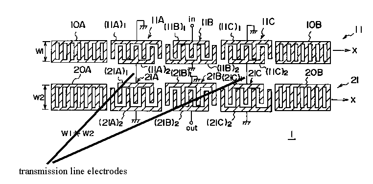
For general remarks concerning SAW coupled resonator filters refer to the description of class H03H 9/6433 in the Definition Editor.
In the present class (H03H 9/6473) are classified documents having:
a) two acoustic tracks performing the filtering; and
b) the two tracks are electrically coupled via two electrically interconnected transmission line electrodes which connect two pairs of IDTs, each pair of IDT having an IDT in the upper track and another in the lower one.
An example is to be found here below:

For general remarks concerning SAW coupled resonator filters refer to the description of class H03H 9/6433 in the Definition Editor.
In the present class (H03H 9/6476) are classified documents having:
a) two acoustic tracks performing the filtering;
b) the two tracks are electrically coupled via two transmission line electrodes; and
c) the two tracks are electrically connected in parallel (i.e. the two transmission line electrodes are connected to the input and to the output of the filter respectively).
d) the two acoustic tracks separated by at least one set of grating reflectors specific to the delimitation of the two resonant cavities.
Some examples are to be found here below:

Fig. 1
In Fig. 1 the reflector 155 is common to the two resonant cavities.
In Fig. 2 the adjacent reflectors producing the separation of the two resonant cavities do not have electrical contact unlike to the structure in Fig. 1 where the reflector is common (reflectors of the two tracks are electrically connected).
It can be seen that the aspects concerning the two series resonators are not taken into account for the purpose of this subclass. The problem solved by the series resonators is most of the time one of improving the steepness of the transition band of the filter. For this purpose the series resonators have to be designed with the resonance frequency having a value which coincides with the beginning of the transition band and the end of the 3dB portion of the pass band.
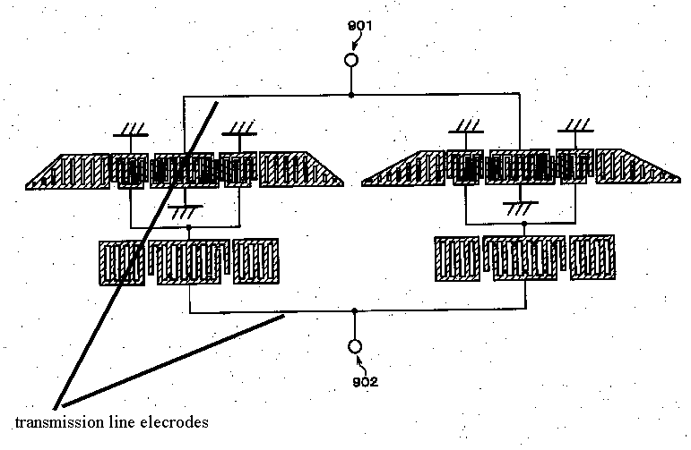
Fig. 2
The following filtering structures are also to be found in the present class H03H 9/6476.
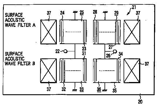
Fig. 3
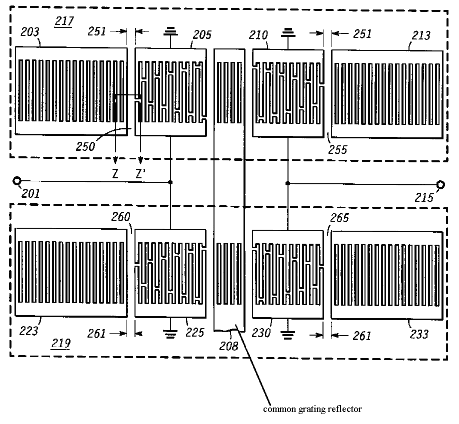
Fig. 4
In Fig. 4 the common grating reflector also needs as technical feature a special entry in H03H 9/645.
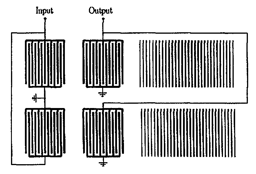
Fig. 5
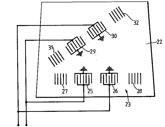
Fig. 6
Disclosures of ladder structures (currently classified in /KW (i.e. - 09saw coupled resonator ladder filter (H03H))) are candidates for the present class if and only if the disclosed embodiments deal with overcoming certain prejudices in the design/production of SAW ladder filters (e.g. adjusting distances between IDTs and/or reflectors, introduction of dummy electrodes, performing cut-outs (holes) in the bus bars or electrodes, etc.).
Otherwise, the simple mention of the possibility of applying a certain structure to the design/production of a ladder filter does not qualify a disclosure to be classified in H03H 9/6483.
The same applies for lattice structures in conjunction with the corresponding /KW (09saw coupled resonator lattice filter (H03H)).
Thales application FA624251 (WO2004/006432) gives a good overview of the related problem.
As SAW and BAW duplexers/diplexers are to be classified in the corresponding subclasses of the present one, in H03H 9/70 one should only classify networks for connecting several sources or loads, working on different frequencies or frequency bands, to a common load or source disclosing
electrostatic driven constructive components:

US3686593
MEMS duplexers (at the moment of printing the present paper no MEMS duplexers are classified in H03H 9/70);
duplexers combining passive or active elements with SAW or BAW devices:
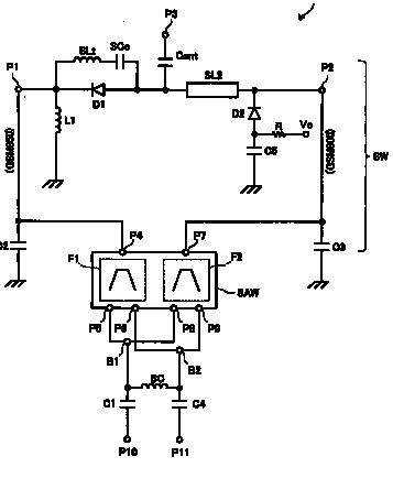
EP1833172 - the present document is also classified in H03H 7/00
non-specific duplexers (the acoustic type of the basic element is not [clearly] specified):
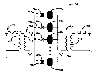
US2004212448
other "exotic" (mostly very old) documents which subscribe to the criterion enounced by the class
However:
- for SAW/BAW spectrum analysers see G01R 23/17 (e.g FR2044148; GB2105939)
- frequency modulators are (also) to be found/classified in H03C 1/46, depending on how much the SAW/BAW aspects are disclosed;
- correlators and convolvers in G06G 7/195, except when there is too much focus on the IDTs and also an entry in H03H could be useful;
When the document discloses details about the basic constructive element as being a BAW, FBAR, SBAR or the like device, without however disclosing a duplexer, the present class should be allocated.
Examples:
dual or multiband filters:
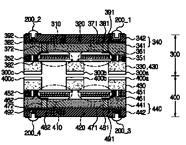
US2007/182510
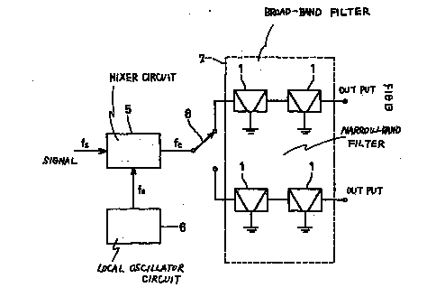
EP1045517
BAW/FBAR frequency multiplexers:
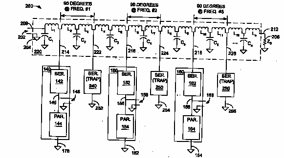
EP1361658
US2002/109430
US4227156
torsional or flexural resonator based structures (resonators per se of this [old] type are currently to be found in H03H 9/17):
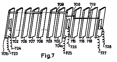
DE2519490
others:
US3602844
Any duplexers having BAW, FBARs, SBAR or the like.
When the document discloses details about the basic constructive element as being a SAW or the like device, without however disclosing a duplexer, the present class should be allocated.
Any duplexers having SAW, interface waves or the like.
In this place, the following terms or expressions are used with the meaning indicated:
BAW | thickness/width shear |
In patent documents, the following abbreviations are often used:
Aperture | overlap, acoustic w beam-width |
Blank | wafer |
Diamond | dlc, (diamond w like w carbon) |
Finger | electrode |
Boundary/interface waves | IAW, QSH, pseudo saw/wave/shear, Stoneley, GBAW, (guided baw/bulk waves), hvpsaw, lpsaw, psaw |
Resin | plastic, epoxy |
SAW | Surface Acoustic Wave |
BAW | Bulk Acoustic Wave |
TFR | Thin Film Resonator |
SBAR (SCF) | Stack Bulk Acoustic Resonator |
SH | Shear Horizontal (waves) |
SSBK | Surface Skimming Bulk (waves) |
BGS | Bleustein-Guliaev-Shimizu (waves) |
DMS | Double Mode SAW |
Duty ratio | metallization w ratio, pitch to width ratio, occupancy ratio, mark to period ratio, line to width ratio |
SBAW, SSBAW | shallow w bulk w acoustic w waves |
STW | surface transverse waves |
RF ID tags | RF Identification tags |
SPUDT | single phase unidirectional transducer |
GBAW | guided BAW |
Attention is drawn to the following places, which may be of interest for search:
Filters comprising resonators of piezoelectric or electrostrictive material |
This place covers:
Gyrators, time-delay networks, phase-shifting networks, impedance matching networks, balanced/unbalanced networks, attenuators and frequency selective networks, such as filters, splitters or duplexers -- all mainly built with active, electrical elements, such as OpAmp, transistors, operational transconductances, Gm-C elements, simulation of reactances, such as active inductors, negative resistances, capacitance multipliers.
Attention is drawn to the following places, which may be of interest for search:
Current converters CCII+, nullor, nulator, rotator | |
Log-domain filters | |
Controller resistors | H03H 11/24 and subgroups |
Circulators, isolators with active elements | |
Integrators, per se | |
Simulation of reactances with applications in amplifiers | H03F 1/56 and subgroups |
Audio equalizers | |
Simulating reactances in tuning context | H03J 3/18 and subgroups |
Time delay networks, esp. built with boolean ports or digital registers | H03K 5/13 and subgroups |
Impedance matching having switching elements or registers | H03K 19/017545 , H03K 19/01825 and H03K 19/018557 and subgroups |
Impedance matching for high speed lines |
In patent documents, the following abbreviations are often used:
active inductor | inductor simulation/emulation/synthesis; inductorless |
Attention is drawn to the following places, which may be of interest for search:
Analogue shift registers |
Examples of places where the subject matter of this place is covered when specially adapted, used for a particular purpose, or incorporated in a larger system:
For use in multiplex transmission systems |
This place does not cover:
Gyrators |
Examples of places where the subject matter of this place is covered when specially adapted, used for a particular purpose, or incorporated in a larger system:
Negative impedance converters used in frequency-selective networks |
This place covers:
Any sampled-data filters in the sense of those filters wherein the input signal is sampled at discrete-time points, so that it consists of discrete amplitude values which are not quantized.
In particular: transversal (FIR) SAMPLED-DATA filters
In particular: recursive (IIR) SAMPLED-DATA (e.g.:XP10728148)
Some general examples:
US2004071244
The output response 220 can match many filter responses (e.g. lowpass, bandpass). Thus, the control signal 212 received by the commutating modulator 206 may include lowpass or bandpass characteristic. The filter responses preferably depend on the impulse response or correlation function encoded within the sigma-delta sequence or the control signal 212
With sample rate conversion:

US2006195883

US2006195883: decimate-by-4 polyphase implementation
Implementing a matched filter:
US6983011
Filter bank implementation:
XP010580981
This place does not cover:
Combinations of digital and sample data filters |
In this place, the following terms or expressions are used with the meaning indicated:
Transversal filter | term used in the past corresponding to what is now commonly understood in the digital domain as Finite Impulse Response (FIR) filters (more commonly, non-recursive filter structures) |
Sampled data filter | filters wherein the input signal is sampled at discrete-time points, so that it consists of discrete amplitude values which are not quantized, including recursive and non-recursive structures. |
In patent documents, the following abbreviations are often used:
CCD | charge-coupled device |
FIR | finite input response |
IIR | infinite input response |
This place covers:
The group contains documents disclosing details of the analog shift registers.
(analog shift registers are in G11C 27/04).
Examples include sampled-data filters comprising charge-coupled devices (a CCD is a device for the movement of electrical charge, usually from within the device to an area where the charge can be manipulated, for example conversion into a digital value. This is achieved by "shifting" the signals between stages within the device one at a time. CCDs move charge between capacitive bins in the device, with the shift allowing for the transfer of charge between bins):
US4264983
US2002062329
US2003014460
input = delta/sigma modulated signals
US2005033792
Delay line implemented as transmisssion line

WO2006119065
An input continuous time signal is successively delayed by a plurality of delay elements to produce a plurality of delayed signals.. A corresponding coefficient is applied to some or all of the plurality of delayed signals to produce a plurality of weighted signals., which are then combined
The filter is programmable: the coefficients are selectable
This place covers:
The group contains sampled-data filters wherein the input is presented in parallel to the memory elements:
US6529926
WO2008032635
This place covers:
Time-delay networks, phase-shifting networks, digital impedance matching networks and frequency selective networks, such as digital filters or sample rate converters
This place does not cover:
Filters for pulse compression | |
Waveform generators | |
Spatial filters in general |
Attention is drawn to the following places, which may be of interest for search:
Details of adding and subtracting | |
Details of sum of products | |
Mathematical transformations, e.g. Fourier transform | |
Computation of correlations | |
Function evaluation by approximation methods, e.g. inter or extrapolation | |
Computation of correlation or computation integrals | |
Data compression by 'thinning' | |
Demodulation by means of matched filters | |
Correction of synchronization errors by interpolation of received data signals |
Filters specially adapted for image processing are, in principle, not to be classified in the group. This rule specifically applies to subgroup H03H 17/0202 (multidimensional filters)
In this place, the following terms or expressions are used with the meaning indicated:
Cepstrum | result of taking the Fourier transform of the log spectrum as if it were a signal. Its name was derived by reversing the first four letters of "spectrum" |
Decimation | reduction of the sampling rate by an integer number |
Delta modulation | any kind kind of (noise sampling) modulator (e.g. sigma/delta) |
Hogenauer filter | simple CIC filter structure |
Interpolation | increase of the sampling rate by an integer number |
Quefrency | refers to operations on cepstra (plural of cepstrum) |
Limit cycles | in IIR filters, undesired generation of oscillating output signal in response to a constant or zero-level input caused by quantization |
Rational or fractional sample rate conversion | conversion of the sampling rate by a rational number |
Warped filter | obtained by replacing the unit delays of a conventional FIR with first-order all-pass filters); the resulting filter has an infinite impulse response (warping makes the filter non-linear) |
In patent documents, the following abbreviations are often used:
CIC | cascaded integrated comb |
CSD | canonic signed digit |
FD | fractional delay |
FIR | finite input response |
IFIR | interpolated FIR |
IIR | infinite impulse response |
MIMO | multiple input – multiple output |
MISO | multiple input – single output |
PTV | periodically time varying |
QMF | quadrature mirror filter |
SRC | sample rate conversion |
S/H circuit | sample/hold circuit |
This place covers:
integer and variable digital delay circuits and any exotic delay circuits.
Also fractional delay lines (DL) with DSP implemented structures ion (i.e. no "interesting" filter structure).
group H03H 17/08 (networks for phase shifting) should be also consulted in combination.
This place covers:
Fractional Delay (FD) filters (or Fractional Sample Delay filters) which cannot be characterized as FIR FD or IIR FD.
Documents are classified in this group and subgroups when they disclose pure FD filters, i.e. without application to src (from now on src = sample rate conversion). If the document describes an src using FD filters classify as convenient in H03H 17/0416 and subgroups, H03H 17/0621 and subgroups.
This place covers:
FIR FD filters like this one:
XP010376249
FD filters are commonly implemented as (Lagrange) interpolators:
XP000106903
The Lagrange interpolators can be implemented by a Farrow structure:
XP000583239
This place covers:
IIR FD filters. They mostly implement Thiran method (recursive counterpart of Lagrange interpolation):
XP010930616
Thiran FD
This place covers:
filter banks (FB) (including sub-band filtering, when not specific for image processing) not characterized by a FIR / IIR implementation.
The group includes FBs implemented with "multirate" techniques, where there is no actual sample rate conversion (i.e. the src aspect is not a goal in itself, since the down-sampling -in the analysis bank- and up-sampling -in the synthesis bank- operations are complementary).
The group also contains numerous examples of polyphase implementations of FBs, normally including a form of DFT (Bellanger, p. 113: "realization of a uniform filter bank through combination of a polyphase network and a DFT computer"). This type of polyphase FB usually implements a channelizer (H04L), related to transmultiplexing.
XP008081118
(Bellanger document)
If the implementation of the FB is polyphase, and if this is relevant in the document, the document should also be classified in H03H 17/0273:
EP0595710
sub-band decomposition (other embodiments give the polyphase implementation)
FBs disclosing relevant details of src are double classified (i.e. add H03H 17/0621 and subgroups, as convenient).
This place covers:
FIR Filter Banks (FBs) implemented with "multirate" techniques, where there is no actual sample rate conversion (i.e. the up-sampling and down-sampling operations are complementary).
Also FBs disclosing relevant details of FIR src. These documents are double classified (i.e. add H03H 17/0621 and subgroups, as convenient).
This place covers:
IIR FBs implemented with "multirate" techniques, where there is no actual sample rate conversion (i.e. the up-sampling and down-sampling operations are complementary).
Also FBs disclosing relevant details of IIR src. These documents are double classified (i.e. add H03H 17/0416 and subgroups, as convenient).
This place covers:
polyphase filters (alternative spelling poly-phase).
The group contains a few documents showing the basic polyphase decomposition, not being applied to FBs or for src:

FR2761550

XP008081118
(Bellanger document)
polyphase implementations of FBs involving DFT (the term "channelizer" is commonly found in this context), where the polyphase decomposition is not relevant are not classified in H03H 17/0273 and subgroups, but in H03H 17/0266 and subgroups.
For example, this FB:
XP008081118
(Bellanger document)
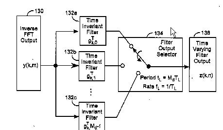
US2005276335
The new group contains also, polyphase implementations where FIR and IIR filters are combined or the distinction FIR - IIR is not important:
Details of src are also classified in H03H 17/0416 and subgroups and in H03H 17/0621 and subgroups.
This place covers:
The group comprises FIR implementation of polyphase filters (i.e. the filters of each branch are FIR):
EP0881764
All documents in this group disclose polyphase implementations of FIR src.
This place covers:
The group comprises two-phase (or two-path) polyphase filters:
US6260053
This place covers:
The group comprises IIR implementation of polyphase filters:
XP008081118
decimator
(Bellanger document)
All documents in this group should disclose polyphase implementations of IIR src (src implemented with polyphase structure comprising IIR filters can be found by crossing this group with H03H 17/0416 and subgroups).
This place covers:
two-phase (or two-path) polyphase filters:
XP000370917
This place covers:
structures implementing polynomial-based filters (which here is taken to includes splines).
For all polynomial-based filters (with the exception of splines) there is a Farrow implementation (if for Fractional Delay (FD), the documents should be classified instead in H03H 17/0027: FIR FD filters).
Farrow implementation:

XP001019533
Based on splines:
EP1313219
the transfer function for the LP filter is approximated by a set of polynomials (splines). In Fig. 4, 4 polynomials are represented each polynomial (45 - 48) corresponds to an interval of 1 pixel. Only the coeffs. of the polynomials piecewise approximating the transfer function of the filter are stored in memory, the coefficients are calculated on-the-fly from the coefficients of the polynomials for any phase difference.
(This is understood according to XP1019533 as: some info. corresponding to the coeffs. must be initially stored; this is the coefficients, i.e. samples of the impulse response h(t) which mark the starting points of the individual polynomial pieces -> for this reason this document is classified in ON-LINE COMPUTATIONS and not in PRE-COMPUTED)
This place covers:
sinc or gaussian filters. A sinc filter is an idealized filter that removes all frequency components above a given bandwidth, leaves the low frequencies alone, and has linear phase. The filter's impulse response is a sinc function in the time domain, and its frequency response is a rectangular function.
US6442580
Gaussian filters are designed to give no overshoot to a step function input while minimizing the rise and fall time.
This place covers:
quite a few documents for which a unifying concept cannot be easily determined. The group must be consulted regularly, if the consultation of subgroups is not successful, it can be searched entirely or combined with subgroups.
This place covers:
asynchronous sample rate converting arrangements:
DE3942818
There is some overlap with H03H 17/0433. The reason is that asynchronous src techniques allow conversions between arbitrary rates. The contrary is not true (see corresponding comment to H03H 17/0422 in the booklet). For that reason the overlap can be tolerated. Documents mentioning and emphasizing the asynchronous technique will be classified in this group (H03H 17/0422). If the aspect of conversion between arbitrary rates is the one emphasized, the class should be H03H 17/0427. If both, double classify.
This place covers:
few documents related to srcs with structures which cannot be classified in the subgroups.
This place covers:
scrs performing arbitrary sample rate conversion or by an irrational (aka incommensurable) factor:
DE3942818
The group includes rational ( = fractional) src, in cases where the numbers are too big to be handled by multi-stage arrangement, or cannot be represented as powers of two (in some cases the src method involves approximations, normally generating noise (jitter)).
The manipulation involved in these techniques appear to allow any conversion rate, and for this reason they are considered not to be limited to src by a fractional delay: these cases should be double classified in H03H 17/0433 and also in H03H 17/0455.
This place covers:
few documents disclosing general details of srcs which cannot be classified in the subgroups.
This place covers:
interpolators (single and multi-stage):
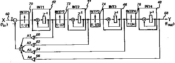
WO9637953
This place covers:
decimators (single and multi-stage):
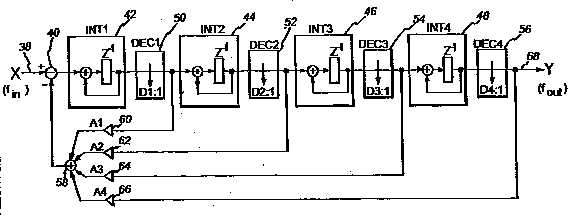
WO9637953
This place covers:
srcs with rational (= fractional) conversion ratio. Normally, multi-stage arrangements comprising up-sampling and down-sampling stages:
EP0516221
When the numbers cannot be handled, approximating techniques are used (see comments to H03H 17/0433) which might be used to handle virtually any fractional rate. For this reason such documents are double classified in H03H 17/0455 and H03H 17/0433.
This place covers:
quite a few documents for which a unifying concept could not be found. The group must be consulted regularly, if the consultation of subgroups is not successful.
In this root group there are examples like this:
US2004184573
US2007046503
In a few cases, documents are classified in this group in addition to another class (purpose: redundancy facilitating recovery), like this one:
 EP1569336
src by direct insertion / cancellation of samples
additional class: H03H 17/0685 (src by a rational factor)
Details of anti-aliasing filters should additionally be classified in this class.
This place covers:
asynchronous srcs:
XP000691530
shows three aspects:
1. INTERRELATION IN CONCEPTS ASYNCHRONOUS -> ARBITRARY
2. ASYNCHRONOUS -> ALWAYS SENSING fin & fout
3. SYNCHRONOUS: RATIO fin/fout SET BY USER
Example using sigma/delta modulation which is considered as asynchronous (and arbitrary) (because of the sigma/delta modulators, this kind of documents are also classified in H03H 17/0614):
EP0512619
method: SAMPLE VALIDATION
There is some overlap with H03H 17/0642. The reason is that asynchronous src techniques allow conversion between arbitrary rates. The contrary is not true (e.g. polynomial-based src can approximate the transfer function and resample it, without requiring asynchronous techniques). For that reason the overlap can be tolerated. Documents mentioning and emphasizing the asynchronous technique will be classified in this group (H03H 17/0628). If the aspect of conversion between arbitrary rates is the one emphasized, the class should be H03H 17/0635. If both, double classify.
US2008027668
Digital phase calibration may be implemented in a similar manner. One statistical value is generated for each phase offset by calculating an absolute value of the scaled signal in one field. The optimum phase offset maximizes the statistical value. In some embodiments, the statistical value is generated by summing absolute values or square values of the filtered signal of the scaler output signal
This place covers:
Few documents related to srcs with structures which cannot be classified in the subgroups.
This place covers:
Scrs performing arbitrary sample rate conversion or by an irrational (aka incommensurable) factor:
XP000948145
with a Farrow implementation of a polynomial based src filter:
XP001019533
The group includes cases of rational (or fractional) src, where:
- the numbers are too big to be handled by multi-stage arrangement, or
- in certain cases where the numbers cannot be represented as powers of two.
In these cases approximations are realized, normally generating noise (jitter). These techniques involving approximations appear to allow any conversion rate, and for this reason they are considered not to be limited to rational src, and are double classified (H03H 17/0642 and H03H 17/0685):
US6226661
To which the following flow-chart corresponds:

US6226661
- structures like PLL are used to generate an effective average sampling rate, i.e. at times the numerator or denominator of the fractional ration is M and at other times M+1, so that the effective value is the average; because of its flexibility, this solution for rational src is double classified as arbitrary and rational (H03H 17/0642 and H03H 17/0685).
US5916301
US5916301
Fractional sample rate conversion "for all synchronous rates where all rates are derived from the same crystal oscillator":
The exact ratio is expressed as [M+N/D]/L with L being a constant. The value of N/D is accumulated and depending on the overflow condition, either M or M+1 is selected as sample rate ratio for the conversion of each sample
This place covers:
Few documents disclosing general details of srcs which cannot be classified in the subgroups.
This place covers:
Interpolators (single and multi-stage):
US2002156820
This place covers:
Decimators (single and multi-stage):
WO2006069743

US6260053
This place covers:
cascaded integrator-comb (CIC) structures and, in general, structures combining integrators and differentiators in combination.
(Atn! CIC structures are sometimes simply called "comb".)

XP010115142
(fig corresponds to P.A. of doc.: implementing an interpolating SINC3 filter)
This place covers:
Srcs with rational (= fractional) conversion ratio. Normally, multi-stage arrangements comprising up-sampling and down-sampling stages:
XP000275090
When the numbers cannot be handled, approximating techniques are used (see comments to H03H 17/0642) which might be used to handle virtually any fractional rate. For this reason such documents are double classified (H03H 17/0685 and H03H 17/0642):
US6226661
To which the following flow-chart corresponds:
US6226661

US2002111980
This place covers:
N-path filters comprising N parallel branches, each with input and output modulators and a time-invariant network which is identical for all branches.
Switched capacitor (SC) networks with building blocks comprising OPAMPS with resistances and switched capacitors at the inputs and / or within feedback networks.
Networks with time-varying elements not susceptible of classification in any of the other main groups.
No digital networks.
This place does not cover:
Amplifiers using switched-capacitors |
Attention is drawn to the following places, which may be of interest for search:
Generating pulses by repetitive charge or discharge of a capacitor | |
Modifications for eliminating interference voltages or currents in field-effect transistor switches |
Switched capacitor networks for a specific purpose (different from filtering) are not classified in H03H 19/00, but in the corresponding application field.
In this place, the following terms or expressions are used with the meaning indicated:
N-path filter | filter with N parallel resistive-capacitive filter sections and a switching arrangement to connect each filter section periodically into an input signal path through the filter, wherein each filter section has an identical transfer function |
Switched capacitor network | electronic circuit element used for discrete time signal processing: capacitors are charged / discharged when switches are opened and closed, under control of non-overlapping signals |
This place covers:
Analog and digital Filters with a closed-loop configuration, wherein the modification of the filter coefficients or transfer function is adaptively performed according to the minimization of a cost function or on performance criteria
This place does not cover:
Multidimensional filters for image processing | |
Automatic control of equalizers | |
Equalizers |
Attention is drawn to the following places, which may be of interest for search:
Adaptive control systems | |
Blind Source Separation | |
Adaptive noise cancellation | |
Adaptive speech recognition | |
Beamforming | |
Adaptive echo cancellation | |
Decision-Feedback equalizers | |
Time-domain equalizers |
Adaptive filters with feedback (closed-loop configurations), wherein the coefficients are not updated based on the minimization of a cost function or performance criteria are considered to be "dynamically reconfigurable" and are classified in H03H 17/0294
In this place, the following terms or expressions are used with the meaning indicated:
Dynamically reconfigurable filters | filters with variable, selectable characteristics, wherein no cost function is minimized |
Shadow filter | case in which two filters are simultaneously adapted, wherein the results of the adaptation process of one of them is used for adapting the other |
Inverse modelling, inverse filtering | process of synthesizing an inverse function H-1(z) of the communication channel transfer function H(z) |
In patent documents, the following abbreviations are often used:
ANC | adaptive noise cancellation |
BSS | blind signal separation |
DFE | decision-feedback equalizer |
FIR | finite impulse response |
IIR | infinite impulse response |
LS | least squares |
MIMO | multiple input – multiple output |
MISO | multiple input – single output |
RLS | recursive least squares |
SG | stochastic gradient |