CPC Definition - Subclass B05B
This place covers:
Apparatus for the release or projection of drops or droplets into the atmosphere or into a chamber to form a mist or the like. The materials to be projected may be suspended in a stream of gas or vapour.
Apparatus as above, for the release or projection of streams or sprays of other fluent materials, e.g. particulate material entrained in a gas, into the atmosphere or into a chamber.
Nozzles or guns for the release of gas only, e.g. air or blowing guns or nozzles.
Projection of droplets of coating material out of numerous closely spaced nozzles by using an inkjet technology to form plain, i.e. not patterned, coating.
Examples of such apparatus, and subcomponents thereof covered by this subclass, include:
- Nozzles, spray heads, shower heads, roses, perforated pipes, spouts or other outlets, with or without auxiliary devices such as valves or heating means.
- Spraying or sprinkling apparatus with moving outlet elements or moving deflecting elements.
- Electrostatic spraying apparatus or installations.
- Spraying apparatus for discharge of liquids or other fluent materials from two or more sources, e.g. of liquid and air or powder and gas.
- Single-unit, i.e. unitary, hand-held apparatus in which flow of liquid is produced by the operator at the moment of use, e.g. by pumping, by squeezing a liquid container or by compressing a compressible bulb.
- Spraying plants, e.g. with means for supporting or feeding work; spray booths.
- Other spraying-type machines or apparatus, including fountains.
- Means for heating, mixing or pressurising of gases, liquids or other fluent materials that are sprayed, sprinkled, misted, released or projected using the apparatus of this subclass.
- Delivery control means or other details or accessories for use with the apparatus of this subclass.
Subclass B05C relates to apparatus for applying liquids or other fluent materials to surfaces in general. This subject matter generally relates to contact methods, e.g. spreading, pouring, dipping, rubbing, or using rollers or fluidized bed techniques, but not to spraying or atomising apparatus that is covered by subclass B05B. Also, subclass B05C relates to apparatus for projecting liquids or other fluent materials onto surfaces (group B05C 5/00) or to the inside of hollow work (subgroup B05C 7/02), and further to apparatus specially adapted for the projection of particulate material onto surfaces (subgroup B05C 19/04). In subclass B05C, 'projection' relates to the application of a continuous stream of liquid or other fluent (e.g. particulate) material to a surface. In subclass B05B, 'projection' relates to the release of a discontinuous stream of drops, droplets or a cloud of particulate material into the atmosphere or into a chamber to form a mist or the like.
Subclass B05D relates to processes (including processes performed by spraying) for applying liquids or other fluent materials to surfaces, in general.
This place does not cover:
Spray-mixers with nozzles | |
Processes for applying liquids or other fluent material to surfaces by spraying |
Examples of places where the subject matter of this place is covered when specially adapted, used for a particular purpose, or incorporated in a larger system:
Dispensing fittings for drip irrigation, e.g. drippers | |
Special adaptations or arrangements of liquid-spraying apparatus for the destruction of noxious animal or plants | |
Dispensers for soap | |
Nozzles for bathing devices for special therapeutic or hygienic purposes | |
Sprayers or atomisers specially adapted for therapeutic purposes | |
Inhalators | |
Nozzles specially adapted for fire-extinguishing | |
Apparatus for spreading or distributing liquids or other fluent materials already applied to a surface with a blast of gas or vapour | |
Cleaning by the force of jets, e.g. blowing-out cavities | |
Spray nozzles, nozzle headers or spray systems for cooling in metal-rolling mills | |
Nozzles for working by laser beam using a fluid stream | |
Machines or devices for abrasive blasting with particulate material | |
Multi-way nozzles specially adapted for injection moulding in making multilayered or multicoloured articles | |
Nozzles for injection moulding | |
Nozzles for ink-jet printing mechanisms | |
Arrangement of nozzles specially adapted for liquid supply in the cleaning of windscreens, windows or optical devices of vehicles | |
Dropping or releasing powdered, liquid or gaseous matter in flight by spraying, e.g. insecticides | |
Nozzles for introducing articles or materials into containers or wrappers | |
Nozzles for delivery of liquid or semi-liquid contents by internal gaseous pressure | |
Filling nozzles for transferring liquid from bulk storage containers or reservoirs into vehicles or into portable containers, e.g. in vehicle service stations | |
Spray quenching devices for heat treatment of metals or alloys | |
Nozzles for drilling by liquid or gas jets | |
Supplying combustion engines in general with combustible mixtures or constituents thereof | |
Nozzles used in connection with end fittings of hoses | |
Atomising devices for mist lubrication | |
Burners |
Attention is drawn to the following places, which may be of interest for search:
Watering gardens, fields, sports grounds or the like | |
Concentration, evaporation or drying of dairy by spraying into a gas stream | |
Processes for coating of sweetmeats or confectionery with atomised liquid, droplet bed or liquid spray | |
Apparatus for coating or filling sweetmeats or confectionery with atomised liquid or liquid spray | |
Pouring spouts of cooking-vessels | |
Spraying devices for supplying cleaning or surface treating agents for cleaning floors, carpets, furniture, walls or wall coverings | |
Dish washing or rinsing machines with spraying devices | |
Disinfection, sterilisation or deodorisation of air using sprayed or atomised substances | |
Separation | |
Processes or devices for granulating materials by dividing liquid material into drops and solidifying the drops | |
Making microcapsules or microballoons by physical processes | |
Cleaning in general by methods involving the use or presence of a liquid | |
Making metallic powder by atomising or spraying | |
Accessories fitted to machine tools for keeping tools or parts of the machine in good working condition or for cooling work | |
Manipulators for painting or coating | |
Severing by means of a fluid jet | |
Coating by incorporating preformed parts or layers for making articles of definite length during shaping by casting of material in a plastic state | |
Coating by incorporating preformed parts or layers for making articles of indefinite length during shaping by casting of material in a plastic state | |
Coating by incorporating preformed parts or layers for making articles of definite length during shaping by coating a mould, core or other substrate of material in a plastic state | |
Coating by incorporating preformed parts or layers for making articles of indefinite length during shaping by coating a mould, core or other substrate of material in a plastic state | |
Coating by incorporating preformed parts or layers for making articles of definite length during shaping by compression moulding of material in a plastic state | |
Coating by incorporating preformed parts or layers for making articles of indefinite length during shaping by compression moulding of material in a plastic state | |
Coating by incorporating preformed parts or layers by injection moulding during shaping of material in a plastic state | |
Coating by incorporating preformed parts or layers by extrusion moulding during shaping of material in a plastic state | |
Layered products, methods or apparatus for making layered products, methods or apparatus for laminating, ancillary operations in connection with laminating processes or operations specially adapted for layered products and not otherwise provided for | |
Aerosol containers | |
Conveying articles or workpieces through baths of liquid | |
Surface treatment of glass, not in the form of fibres or filaments, by coating | |
Surface treatment of fibres made from glass, minerals or slags by coating | |
Coating or impregnating after-treatment of mortars, concrete, stone or ceramics | |
Coating or impregnation after-treatment of only artificial stone | |
Coating or impregnation after-treatment of only ceramics | |
Coating compositions, e.g. paints, varnishes or lacquers | |
Coating metallic material; Coating material with metallic material; Surface treatment of metallic material by diffusion into the surface, by chemical conversion or substitution; Coating by vacuum evaporation, by sputtering, by ion implantation or by chemical vapour deposition, in general | |
Processes for the electrolytic or electrophoretic production of coatings, e.g. electroplating; Electroforming; Apparatus therefor | |
Treating of textile materials by liquids, gases or vapours | |
Treating roads | |
Pillar fountains or like apparatus for dispensing drinking water, e.g. drinking fountains | |
Jet regulators or jet guides, e.g. anti-splash devices, for fresh water taps | |
Positive-displacement machines for liquids; Pumps for liquids or elastic fluids | |
Valves; Taps, e.g. water-taps | |
Burners using a direct spraying action of liquid droplets or vaporised liquid into the combustion space | |
Liquid ejecting guns, e.g. water pistols | |
Measuring volume, flow or liquid level, e.g. dosing | |
Manufacturing of record carriers | |
Manufacture or treatment of individual inorganic light-emitting semiconductor devices having potential barriers, e.g. light-emitting diodes [LED] | |
Manufacture or treatment of semiconductors or solid-state devices, or of parts thereof |
Apparatus for applying fluent materials to surfaces, in general, e.g. arrangements for cleaning discharge openings, devices or dispensing heads, of apparatus belonging to subclass B05C are classified in the relevant place of B05C, as well as in B05B 15/50.
Considering the possible broad interpretation of the scope of subclass B05B, it is essential to pay attention to all references appearing in many titles of the B05B places. All devices relating to specific application fields are normally not classified in B05B unless some general function aspects are considered of relevance and are therefore (also) classified in subclass B05B.
In this place, the following terms or expressions are used with the meaning indicated:
coating | the applied material. A coating may be a solidified layer originally applied as a liquid (e.g. dried paint) or a layer of material which, once applied, remains in a liquid or semi-liquid state (e.g. lubricant). |
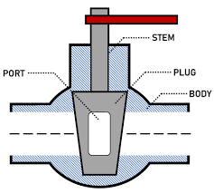
cock | a valve as defined in group F16K 5/00, i.e. a cut-off apparatus having at least one of the sealing faces shaped as a more or less complete surface of a solid of revolution, the opening and closing movement being predominantly rotary. The Figure illustrates body, plug, port and stem: |
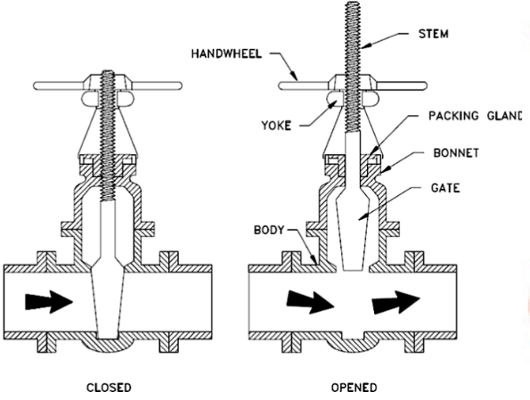
gate valve or sliding valve | a valve as defined in group F16K 3/00, i.e. a cut-off apparatus with closure members having a sliding movement along the seat for opening and closing. The Figure illustrates a closed valve position and an opened valve position with body, gate, bonnet, packing gland, yoke, handwheel and stem: |
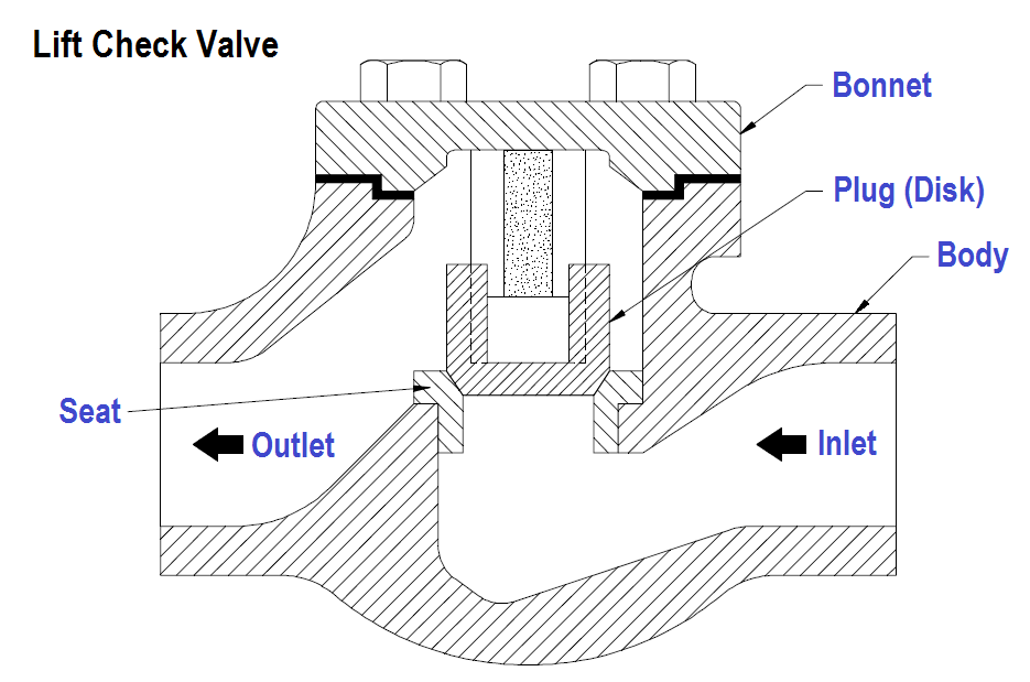
lift valve | a valve as defined in group F16K 1/00, i.e. a cut-off apparatus with closure members having at least a component of their opening and closing motion perpendicular to the closing faces. The Figure illustrates body, inlet, outlet, seat, plug (disk) and bonnet: |
liquid or fluent | designates materials that can flow, e.g. liquids, including solutions, dispersions, suspensions, semi-liquids, pastes, melts or particulate materials |
particulate materials | solid materials in the form of very small pieces, e.g. powders, granules, short fibres or chips |
In patent documents, the following words/expressions are often used as synonyms:
- "to atomize", "to spray", "to nebulize", "to disperse", "to project", "to release", "to discharge" and "to dispense"
- "spray", "jet", "mist" and "discharge"
This place does not cover:
Spraying or sprinkling apparatus with moving outlet elements or moving deflecting elements | |
Electrostatic spraying apparatus; Spraying apparatus with means for charging the spray electrically; Apparatus for spraying liquids or other fluent materials by other electric means | |
Spraying apparatus for discharge of liquids or other fluent materials from two or more sources, e.g. of liquid and air, of powder and gas | |
Devices for applying liquids or other fluent materials to surfaces by contact | |
Nozzles for ink-jet printing mechanisms | |
Nozzles for liquid-dispensing, e.g. in vehicle service stations |
Examples of places where the subject matter of this place is covered when specially adapted, used for a particular purpose, or incorporated in a larger system:
Nozzles for baths with water or gas jets | |
Nozzles specially adapted for fire-extinguishing | |
Nozzles for generating high velocity abrasive fluid jets | |
Additive manufacturing nozzles | |
Nozzles, funnels or guides for introducing articles or materials into containers or wrappers | |
Fuel-injection nozzles | |
Nozzles specially adapted for burners using a direct spraying action of liquid droplets into the combustion space |
Attention is drawn to the following places, which may be of interest for search:
Electroforming of hollow bodies, e.g. nozzles |
This place covers:
Illustrative examples of subject matter classified in this place:
1a.
1b.
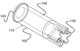
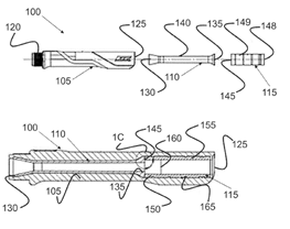
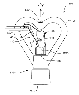
Figures 1a and 1b illustrate a noise suppressor (115) within a nozzle (100). The geometry of a suppressor (115) results in a reduction of aero-acoustic energy at certain operating pressures.
2.
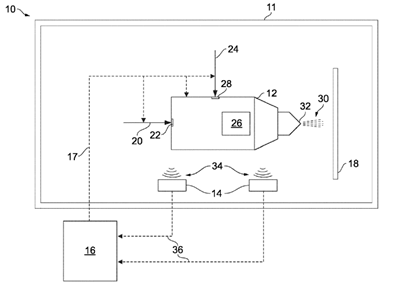
Figure 2 illustrates acoustic sensors (14) configured to sense acoustic signals (34) generated by one or more components or processes of a thermal spray system (10).
3.
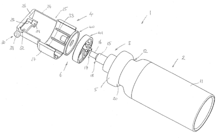
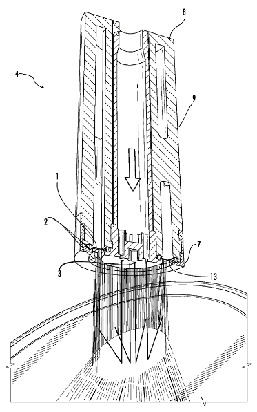
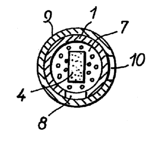
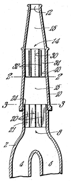
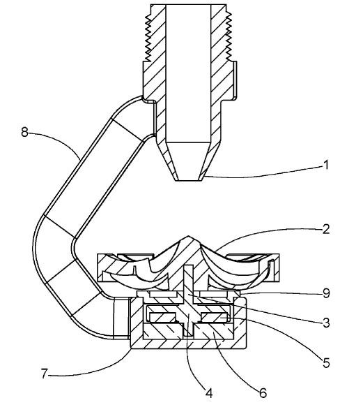
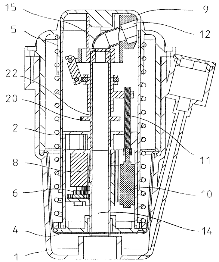
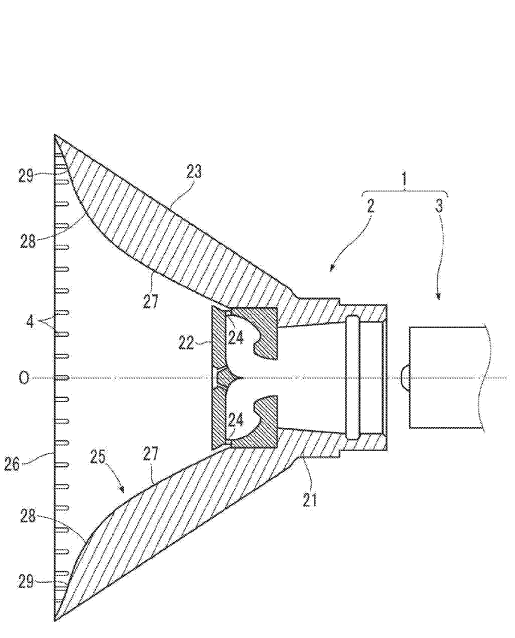
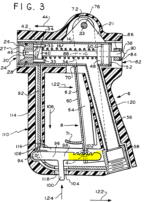
Figure 3 illustrates a handheld pump sprayer (1), wherein depression of an actuator (4) compresses a mechanical clicker (6). This compression is accompanied by an audible clicking sound that provides a clear and reliable indication to a user that stem (18) of a pump (3) has been sufficiently depressed.
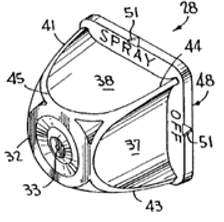
4.
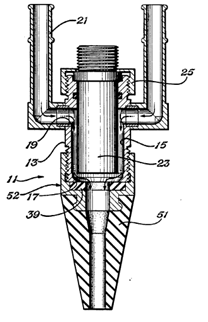
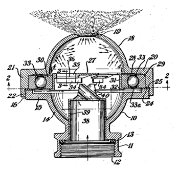
Figure 4 illustrates a ring (39) and nozzle (51) made of an elastomeric material containing metal oxide particles to absorb unwanted sound energy.
Attention is drawn to the following places, which may be of interest for search:
Methods or devices for protecting against, or for damping, noise or other acoustic waves in systems with fluid flow in general |
This place covers:
Illustrative examples of subject matter classified in this place:
1.
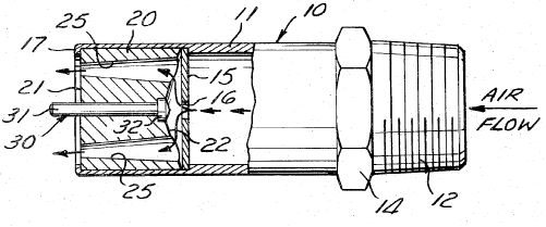
Figure 1 illustrates a nozzle (25) having multiple outlets (25) specially adapted for discharging air.
2.
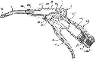
Figure 2 illustrates an air blow gun.
Attention is drawn to the following places, which may be of interest for search:
Gas streams controlling the spraying area | |
Blower devices for sweeping lawn debris | |
Gas nozzles for spreading liquids or other fluent materials already applied to a surface | |
Cleaning by the force of air or gas jets | |
Air blowing devices for filling or emptying large containers | |
Outlets for directing or distributing air or other gases for drying solid materials or objects | |
Compressed-gas guns; Steam guns |
This place covers:
Illustrative example of subject matter classified in this place:
1a.
1b.
Figures 1a and 1b illustrate a perpendicular nozzle defining the plane of the jet.
This place does not cover:
Slits, i.e. narrow openings defined by two straight and parallel lips; Elongated outlets for producing very wide discharges | |
Outlets formed, e.g. cut, in the circumference of tubular or spherical elements |
This place covers:
Illustrative example of subject matter classified in this place:
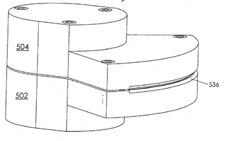
The Figure illustrates two straight and parallel lips defining an elongated slotted outlet (536).
This place does not cover:
Outlets formed, e.g. cut, in the circumference of tubular or spherical elements |
Attention is drawn to the following places, which may be of interest for search:
Fountains designed to produce sheets or curtains of liquid |
This place covers:
Illustrative example of subject matter classified in this place:
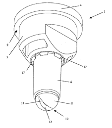
The Figure illustrates an outlet (12) that is formed by a cut in the circumference of a spherical element (8).
This place covers:
Illustrative example of subject matter classified in this place:
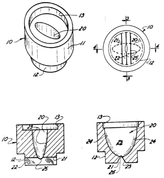
The Figure illustrates a conduit (20) having an ellipse shaped cross-section, wherein the major axis of the conduit (20) is perpendicular to that of the plane of the jet.
This place covers:
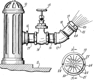
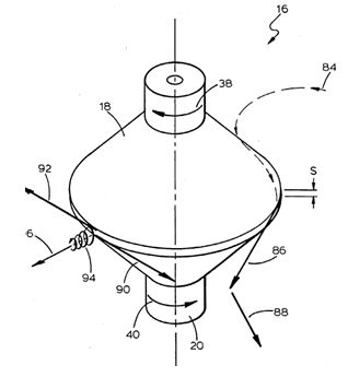
Illustrative examples of subject matter classified in this place:
1.
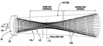
Figure 1 illustrates a spray jet (102) being shaped as a hollow conical form, which includes a dry zone line above and a typical spray zone line below, both divided into a power zone (converged toward the vertical line 113) nearest to the spray jet (101, 103 on the left) and a coverage zone (diverged toward the right side) beyond the power zone.
2.
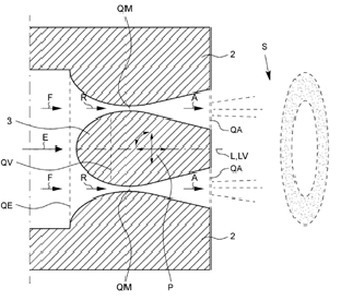
Figure 2 illustrates a spray jet (S) being annularly shaped.
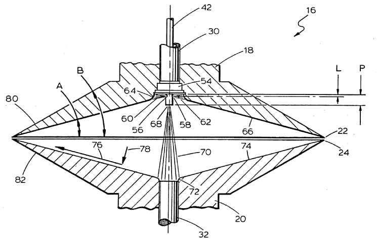
This place covers:
Illustrative example of subject matter classified in this place:
The Figure illustrates fluidic oscillators.
Attention is drawn to the following places, which may be of interest for search:
Spraying apparatuses controlled to effect pulsating flow | |
Oscillators as circuit elements having no moving parts |
This place covers:
Illustrative example of subject matter classified in this place:
The Figure illustrates a liquid rotated turbine (2) being rotated by the fluid being discharged, thus producing a pulsating discharge.
This place covers:
Illustrative example of subject matter classified in this place:
1a.

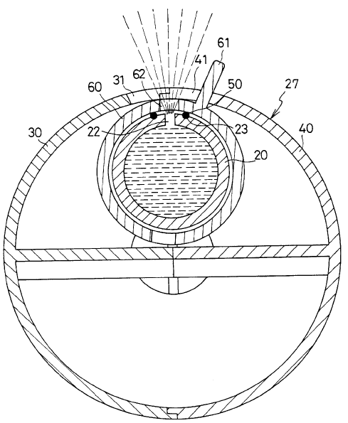
1b.
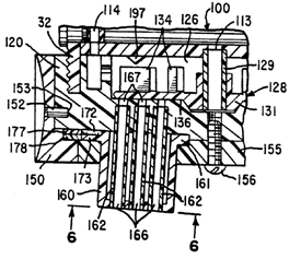
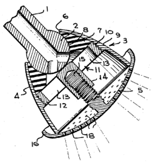
Figure 1a illustrates a shower head (15) comprising three cup-shaped discharge caps (160). Figure 1b illustrates a cap (160) comprising a turbine (128) creating a pulsating discharge.
This place covers:
Illustrative example of subject matter classified in this place:
1a.
1b.

Figure 1a illustrates a shower head (15) comprising three cup-shaped discharge caps (160). Figure 1b illustrates each cap (160) comprising a turbine (128) creating a pulsating discharge. Rotation of the turbine (128) can be prevented by a stop (197).
This place covers:
Illustrative example of subject matter classified in this place:
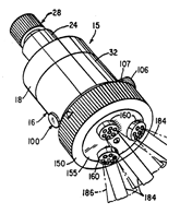
The Figure illustrates how water flowing through openings (70) rotates balls (56) around annular channels (54) to successively cover and uncover openings (64), thereby causing the water to exit from these openings in the form of pulsating jets.
This place covers:
Illustrative example of subject matter classified in this place:
1a.
1b.
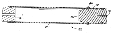
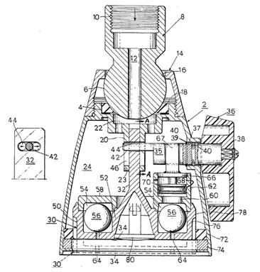
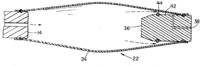
Figure 1a illustrates the expansion of a tube (24) enabling discharge through a channel (38). As the substance rushes out through the channel (38), the tube (24) collapses and returns to a configuration similar to that shown in Figure 1b. As this occurs, the seal between the tube (24) and an O-ring (44) once again becomes effective in Figure 1b, and the cycle will repeat, thus creating a pulsating discharge.
This place covers:
Illustrative examples of subject matter classified in this place:
1a.
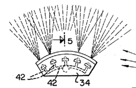
Figure 1a illustrates nozzles forming an array of fine jets.
1b.
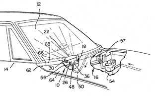
Figure 1b illustrates a nozzle array positioned onto a car windshield.
2.
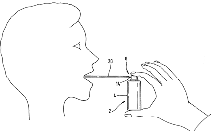
Figure 2 illustrates a nozzle (14) forming a single fine jet (20).
This place covers:
Illustrative example of subject matter classified in this place:
1a.
1b.
Figures 1a and 1b illustrate a singular outlet that is capable of producing different kinds of selected discharge, either spray or stream.
This place does not cover:
Nozzles with multiple outlet openings or strainers having selectively-effective outlets in or outside the outlet opening |
This place does not cover:
Nozzles designed to produce a jet, spray or other discharge of particular shape or nature, or having an outlet of particular shape | |
Nozzles with means for mechanically breaking up or deflecting the jet after discharge; Nozzles with means for breaking up the discharged liquid or other fluent material by impinging jets |
Attention is drawn to the following places, which may be of interest for search:
Filters located upstream of the spraying outlets |
This place covers:
Illustrative example of subject matter classified in this place:
The Figure illustrates two identical rows or groups of outlet openings (41).
This place covers:
Illustrative example of subject matter classified in this place:
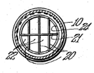
The Figure illustrates radial concentric or coaxial groups of outlet openings (22).
This place covers:
Illustrative example of subject matter classified in this place:
The Figure illustrates multiple outlet openings (186) that go through a convex wall (165).
This place covers:
Illustrative example of subject matter classified in this place:
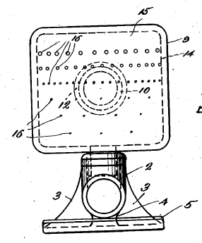
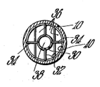
The Figure illustrates a plurality of dissimilar rows of orifices (16), the orifices (16) being arranged in three or more dissimilar rows.
This place does not cover:
Nozzles with a selecting mechanism comprising a gate valve, sliding valve or cock and a lift valve |
Attention is drawn to the following places, which may be of interest for search:
Lift valves in general |
This place covers:
Illustrative example of subject matter classified in this place:
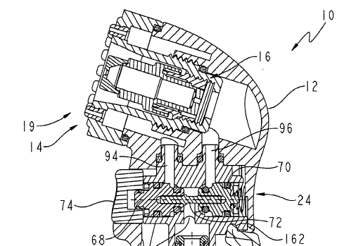
The Figure illustrates a valve assembly (24) that is actuated by a button (74), the valve assembly (24) having two valve seats allowing for two separate flows to be utilised.
This place does not cover:
Nozzles with a selecting mechanism comprising a gate valve, sliding valve or cock and a lift valve |
This place covers:
Illustrative example of subject matter classified in this place:
1a.
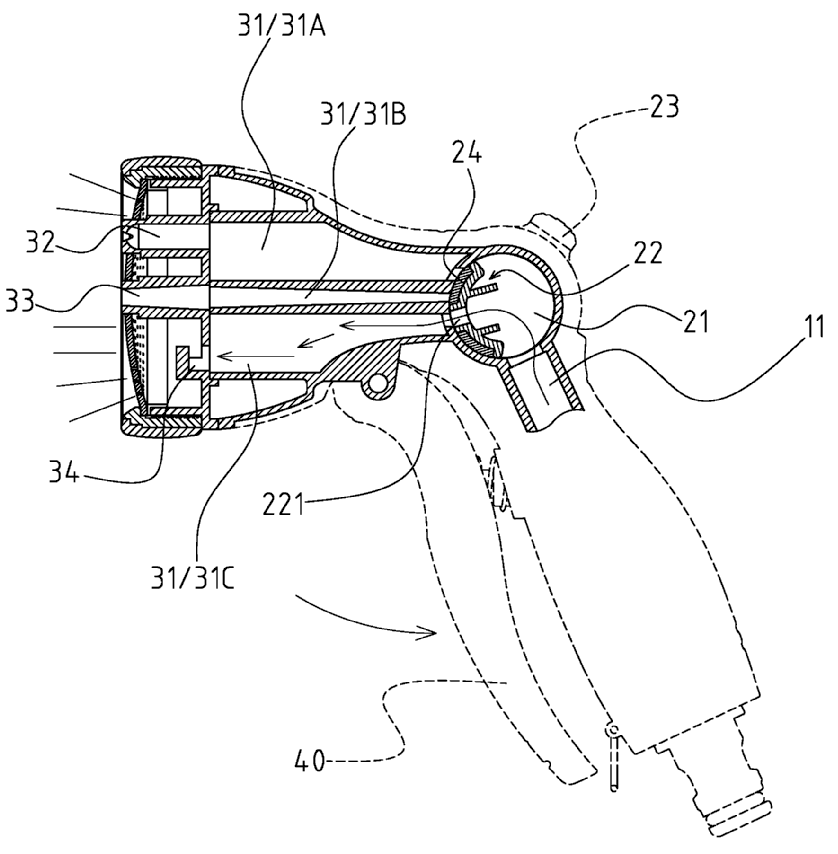
1b.
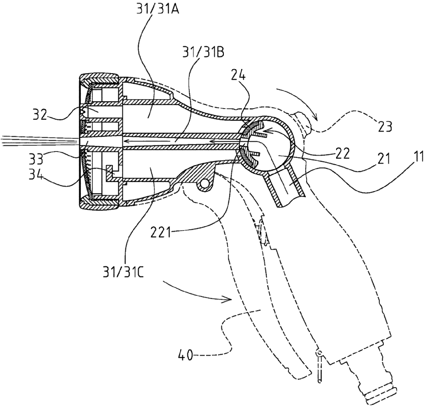
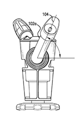
Figures 1a and 1b illustrate a water passage (221) that can be rotated to selectively bring either of the outlets (32) and (33) into fluid communication with a passage (11).
This place does not cover:
Nozzles with multiple outlet openings having selectively-effective outlets being arranged on a tube or pipe |
This place covers:
Illustrative examples of subject matter classified in this place:
1a.
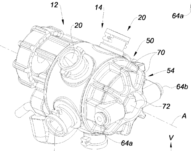
1b.
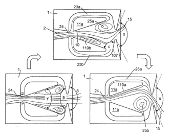
Figures 1a and 1b illustrate a turret (14) rotatably mounted on a body (12) around an axis (A) to bring one of the outlets (20) into fluid communication with an inlet passage (24).
2a.
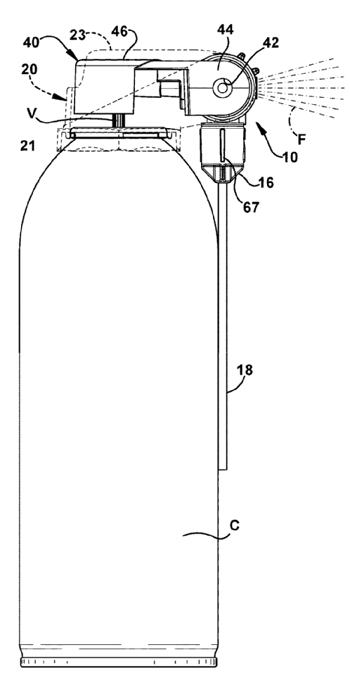
Figure 2a illustrates a downward position of an outlet tube (18) supplied by a rotatable valve assembly.
2b.
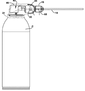
Figure 2b illustrates a horizontal position of an outlet tube (18) supplied by a rotatable valve assembly.
2c.
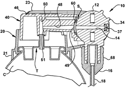
Figure 2c illustrates an expanded view of a rotatable valve assembly (12) enabling outlets (37) and (18) to be brought selectively into fluid communication with a passage (48).
This place covers:
Illustrative example of subject matter classified in this place:
1a.
1b.
Figures 1a and 1b illustrate various outlets (161) rotatably mounted about an axis parallel to the liquid passage of the valve element.
This place covers:
Illustrative example of subject matter classified in this place:
1a.
1b.
1c.
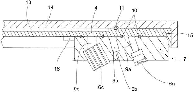
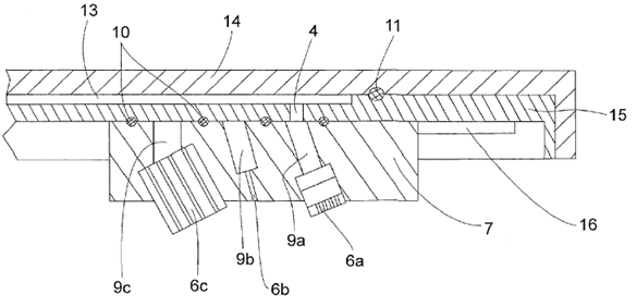
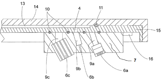
Figures 1a, 1b and 1c illustrate a jet selection plate (7) repositionable to the left or to the right, bringing stationary water outlet (4) into fluid communication with jet chambers in three positions (9a, 9b or 9c) and thus into fluid communication with corresponding outlets of jet-forming bodies (6a, 6b or 6c) of the jet selection plate (7).
This place does not cover:
Nozzles with multiple outlet openings having selectively-effective outlets being arranged on a tube or pipe |
This place covers:
Illustrative example of subject matter classified in this place:
1a.
1b.
1c.
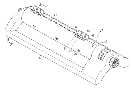
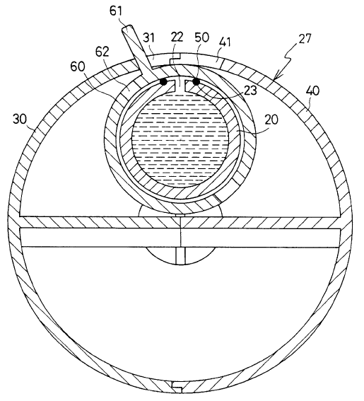
Figures 1a, 1b and 1c illustrate selectively effective outlets (21, 22) being arranged on pipe (20).
This place covers:
Illustrative example of subject matter classified in this place:
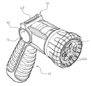
The Figure illustrates a spray head having three or more selectively effective outlets (161).
This place covers:
Illustrative example of subject matter classified in this place:
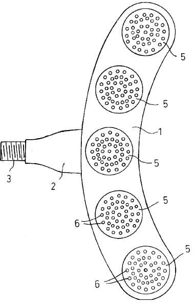
The Figure illustrates a shower head having multiple identical groups.
This place covers:
Illustrative example of subject matter classified in this place:
The Figure illustrates a shower head having multiple outlet groups that are concentric.
This place covers:
Illustrative example of subject matter classified in this place:
1a.
1b.
Figures 1a and 1b illustrate a shower head having multiple outlet groups that are concentric and wherein the outlets traverse a concavo-convex outlet wall.
This place covers:
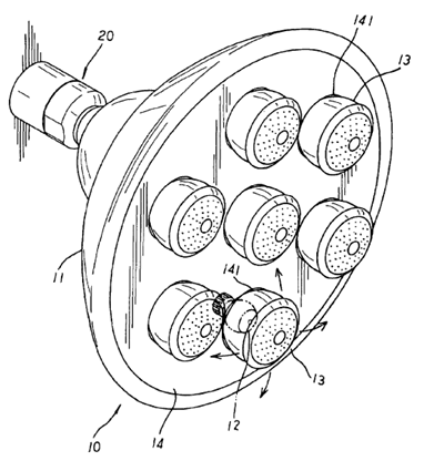
Illustrative example of subject matter classified in this place:
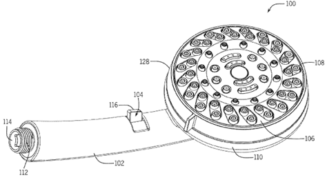
The Figure illustrates a shower head (100) with three or more dissimilar outlet groups.
This place covers:
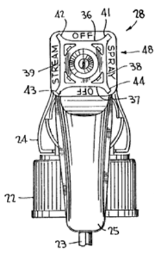
Illustrative example of subject matter classified in this place:
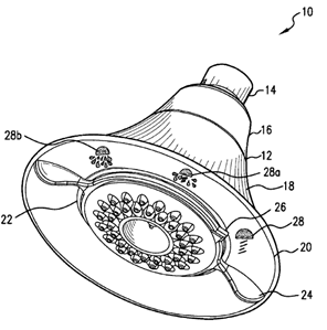
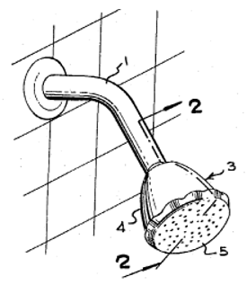
The Figure illustrates a shower head (10) having multiple elements (28, 28a, 28b) that show the corresponding spray pattern when selected by indicator (26).
This place covers:
Illustrative example of subject matter classified in this place:
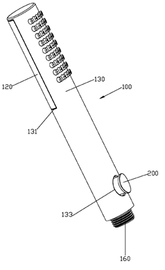
The Figure illustrates a shower head provided with a push-button (200).
This place covers:
Illustrative example of subject matter classified in this place:
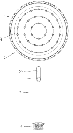
The Figure illustrates a shower head (1) provided with a linearly slidable actuator (11).
This place covers:
Illustrative examples of subject matter classified in this place:
1a.
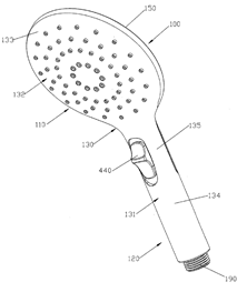
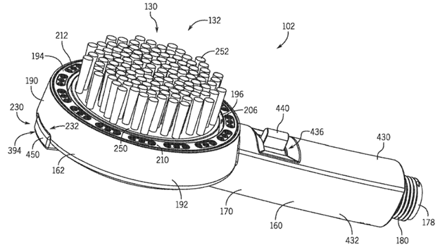
Figure 1a illustrates a shower head having linear actuation converted into rotational movement.
1b.
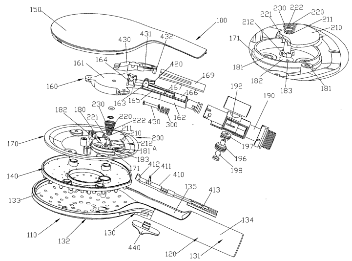
Figure 1b illustrates a shower head provided with a linearly slidable actuator (440) whose actuation rotates element (430).
2.
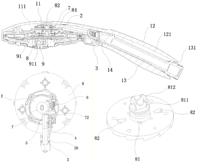
Figure 2 illustrates a shower head provided with a push-button (3) whose actuation rotates a ratchet wheel (7).
This place covers:
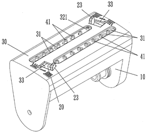
Illustrative example of subject matter classified in this place:
The Figure illustrates a shower head (102) provided with a pivoting lever (440).
This place covers:
Illustrative example of subject matter classified in this place:
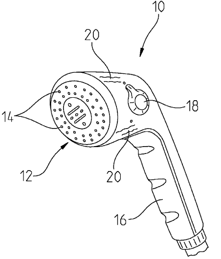
The Figure illustrates a shower head (10) provided with a rotating controlling element (18).
This place covers:
Illustrative example of subject matter classified in this place:
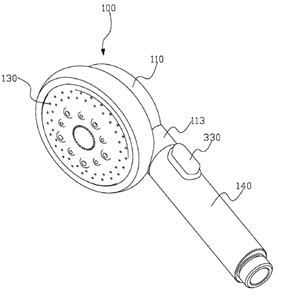
The Figure illustrates a shower head (100) provided with a controlling member (330) located on a handle (140).
This place covers:
Illustrative example of subject matter classified in this place:
1a.
1b.
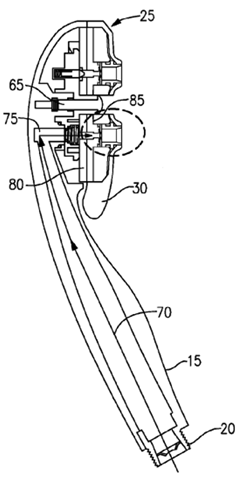
Figures 1a and 1b illustrate a shower head (10) provided with a controlling element (30) located on the outlet wall (25).
This place covers:
Illustrative examples of subject matter classified in this place:
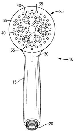
1.
Figure 1 illustrates a shower head (10) provided with a ring controlling element (20) being part of the shower head housing.
2.
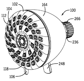
Figure 2 illustrates a shower head (100) provided with a lever controlling element (248) being located on the shower head housing (164).
Attention is drawn to the following places, which may be of interest for search:
Spray booms for agricultural uses | |
Spray bars for treating roads |
This place covers:
Illustrative example of subject matter classified in this place:
The Figure illustrates outlets (14) comprising inserted elements (16) along an elongated tubular body (12).
This place covers:
Illustrative examples of subject matter classified in this place:
1.
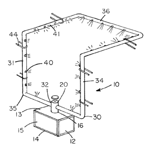
Figure 1 illustrates a first arrangement (10) of several nozzles (40) along a closed loop (31).
2.

Figure 2 illustrates a second arrangement (130) of several openings (132) along a closed loop (138).
Attention is drawn to the following places, which may be of interest for search:
Shower rings |
This place covers:
Illustrative example of subject matter classified in this place:
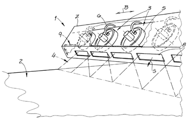
1a.
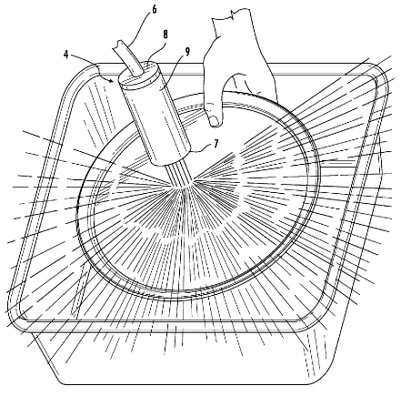
Figure 1a illustrates splashing from a stream of water discharged by a nozzle (7) from a spout (9).
1b.

1c.
Figures 1b and 1c illustrate how an outer stream of water discharged by nozzles (2) prevents unwanted splashing from an inner stream of water discharged by nozzles (3) in a spout (4).
This place does not cover:
Anti-splash devices for water-taps |
This place covers:
Illustrative example of subject matter classified in this place:
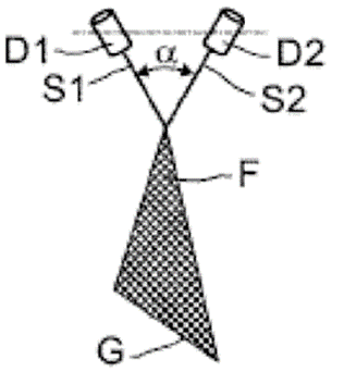
The Figure illustrates two impinging jets (S1) and (S2).
Attention is drawn to the following places, which may be of interest for search:
Valves acting as deflectors | |
Flow controlling element comprising both a lift valve and a deflector |
Attention is drawn to the following places, which may be of interest for search:
Spraying with rotating elements in association with stationary outlet or deflecting elements |
This place covers:
Illustrative example of subject matter classified in this place:
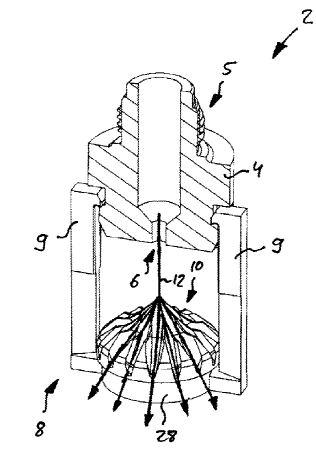
The Figure illustrates a fluid (12) being discharged from nozzle (6) and symmetrically deflected over a deflector (10).
Attention is drawn to the following places, which may be of interest for search:
Rotary deflector rotated by the liquid discharged |
This place covers:
Illustrative example of subject matter classified in this place:
1a.
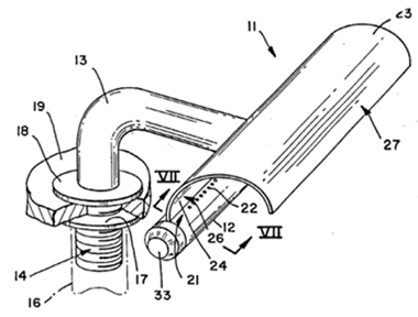
1b.
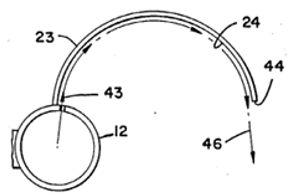
Figures 1a and 1b illustrate a deflector element (11) allowing for deflection in a determined direction (46).
This place covers:
- Nozzles, spray heads or other fluid spraying outlets in combination with shielding elements attached to or integrally formed with the outlet elements, which block or shield a portion of the fluid discharged from the outlet elements, e.g. in order to limit the area of fluid spray.
- Nozzles, spray heads or other fluid spraying outlets in combination with integrally formed means for catching drips or collecting surplus liquid or other fluent material, e.g. in order to collect undesired surplus fluid.
Illustrative example of subject matter classified in this place:
The Figure illustrates a spray shield (90) to limit the area of spray.
Examples of places where the subject matter of this place is covered when specially adapted, used for a particular purpose, or incorporated in a larger system:
Arrangements for controlling the spray area | |
Shielding elements for controlling the spray area | |
Arrangements for collecting, re-using or eliminating excess spraying material |
This place covers:
Illustrative example of subject matter classified in this place:
1a.
1b.
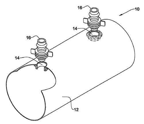
1c.
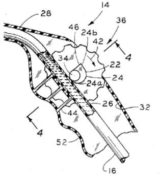
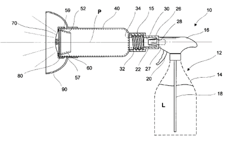
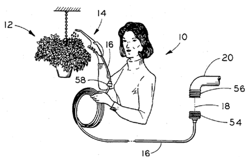
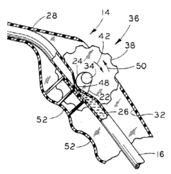
Figures 1a, 1b and 1c illustrate fluid control by pinching of supply tube (16) for watering a plant (12).
This place does not cover:
Single-unit, hand-held apparatus comprising a container and a discharge nozzle attached thereto, in which flow of liquid or other fluent material is produced by the muscular energy of the operator at the moment of use or by an equivalent manipulator independent from the apparatus components or details including movable dispensing tubes, e.g. articulated on the sprayer |
Attention is drawn to the following places, which may be of interest for search:
Control of flow in apparatuses discharging fluid from an orifice in contact with the surface of a work to be coated | |
Control of flow in installations for distributing water | |
Valves; Taps; Cocks; Actuating-floats; Devices for venting or aerating | |
Control of flow in general |
This place covers:
Illustrative example of subject matter classified in this place:
1a.
1b.
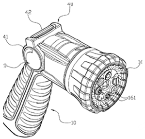
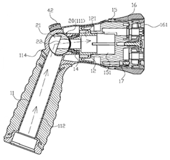
Figures 1a and 1b illustrate a nozzle (10) with an internal valve in the first image that is actuated to open when fluid is applied to the sprayer, as shown in the second image.
This place does not cover:
Nozzles, spray heads or other outlets designed to control volume of flow, in which a valve member forms part of the outlet opening and in which the valve member is actuated by the pressure of the fluid to be sprayed | |
Single-unit, hand-held apparatus comprising a container and a discharge nozzle attached thereto, in which flow of liquid or other fluent material is produced by the muscular energy of the operator at the moment of use or by an equivalent manipulator independent from the apparatus, components or details including outlet valves actuated by the pressure of the fluid to be sprayed |
Attention is drawn to the following places, which may be of interest for search:
Flow or pressure regulators | |
Diaphragms actuated by fluid pressure in valves in general | |
Deformable sensing element acting as a valve for controlling flow in general |
This place covers:
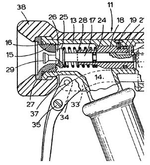
Illustrative example of subject matter classified in this place:
1a.
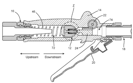
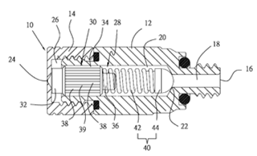
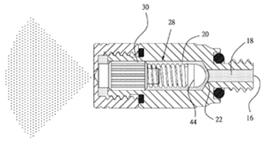
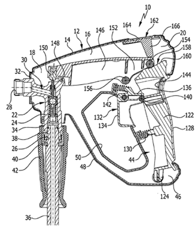
Figure 1a illustrates a lift valve (12) indicating upstream flow to the left and downstream flow to the right.
1b.
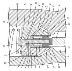
Figure 1b illustrates the valve (12) closed as achieved by the lever (20) in Figure 1a.
1c.
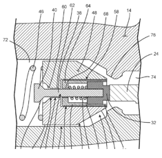
Figure 1c illustrates the valve (12) open in position, as achieved by the lever (20) in Figure 1a.
This place does not cover:
Nozzles, spray heads or other outlets designed to control volume of flow, the control being effected by relative coaxial longitudinal movement of the controlling element and the spray head |
Attention is drawn to the following places, which may be of interest for search:
Nozzles, spray heads or other outlets designed to control volume of flow, the controlling element being actuated by the pressure of the fluid to be sprayed | |
Lift valves in general |
This place covers:
Illustrative example of subject matter classified in this place:
1a.
1b.

Figures 1a and 1b illustrate a lift valve (22), which includes a ball shaped valve member (86) depicted in Figure 1b.
Attention is drawn to the following places, which may be of interest for search:
Ball-shaped valve members in general |
This place covers:
Illustrative example of subject matter classified in this place:
1a.

Figure 1a illustrates a cock in an open position (80), which acts as the controlling element to control the flow of fluid upward to an outlet (16).
1b.
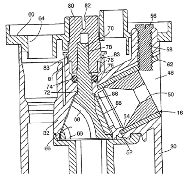
Figure 1b illustrates the cock (80) in a closed position.
This place does not cover:
Nozzles, spray heads or other outlets designed to control volume of flow, in which a valve member forms part of the outlet opening and in which the valve is a gate valve, a sliding valve or a cock |
Attention is drawn to the following places, which may be of interest for search:
Nozzles, spray heads or other outlets designed to control volume of flow, the controlling element being actuated by the pressure of the fluid to be sprayed | |
Gate or sliding valves in general | |
Cocks in general |
This place covers:
Illustrative example of subject matter classified in this place:
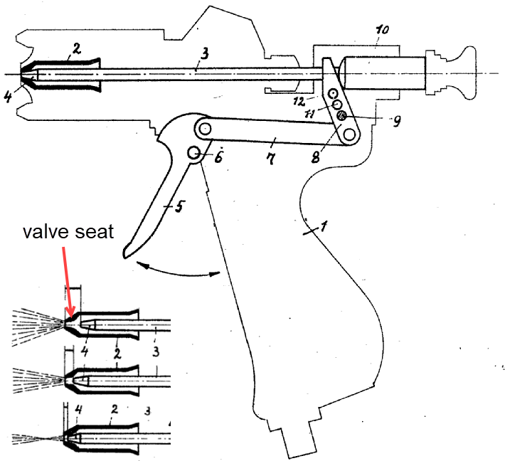
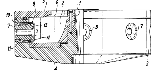
The Figure illustrates a spray gun with a "valve seat" located downstream of a movable valve element (4).
This place does not cover:
Nozzles, spray heads or other outlets designed to control volume of flow, in which the control is effected by relative coaxial longitudinal movement of the controlling element and the spray head, and in which the controlling element comprises both a lift valve and a deflector |
This place covers:
Illustrative example of subject matter classified in this place:
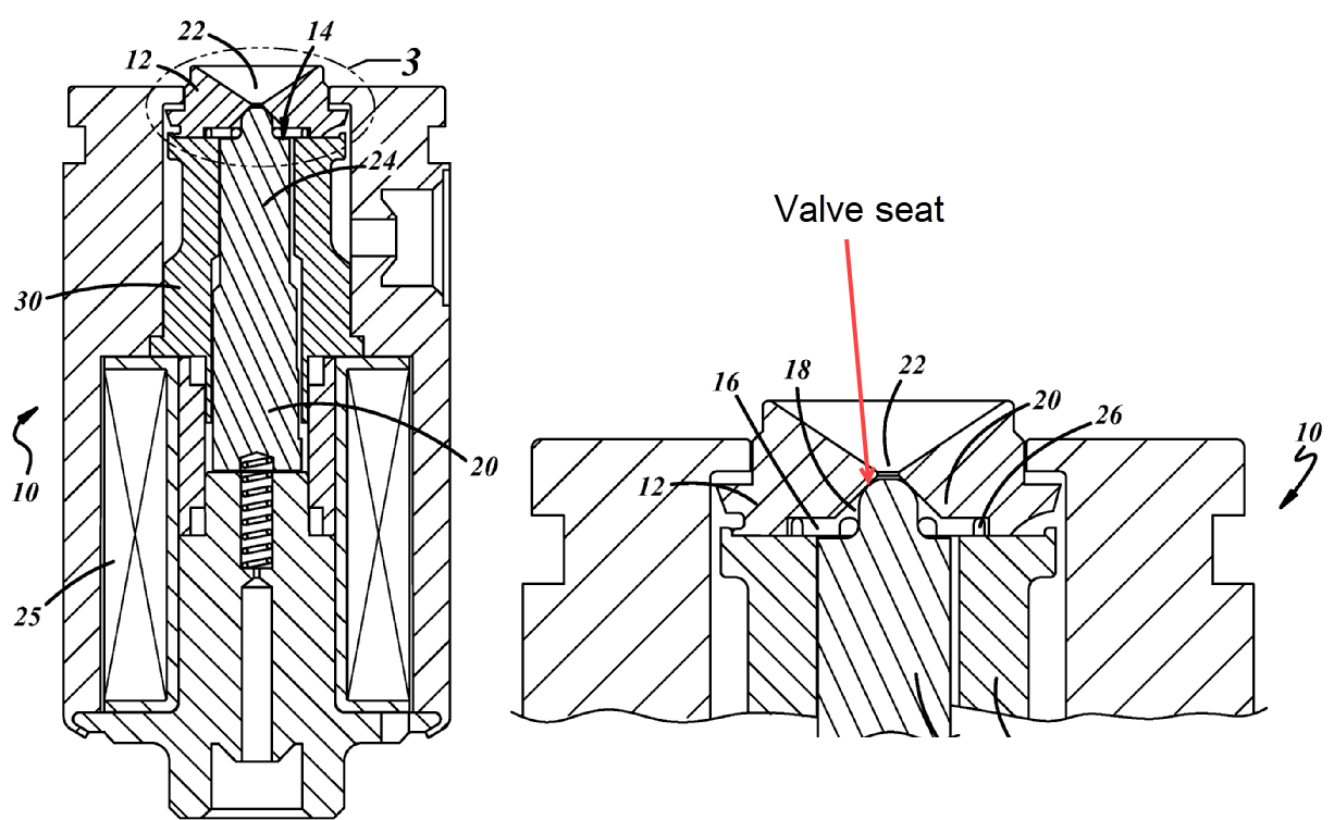
The Figure illustrates a solenoid (25) that controls the movement of a lift valve element (20) for controlling the volume of flow through the outlet towards (22), wherein the valve seat is located downstream of a movable lift valve element (20).
This place covers:
Illustrative example of subject matter classified in this place:
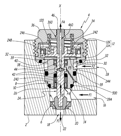
The Figure illustrates an intake duct (28) for a pressurized control fluid flow (F2), e.g. compressed air, which controls the movement of lift valve element (240) for controlling the volume of flow (F1) through outlet (18), wherein a valve seat (20) is located downstream of a movable valve element (240).
This place covers:
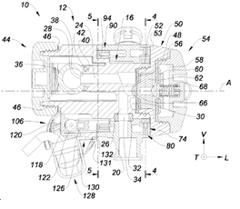
Illustrative example of subject matter classified in this place:
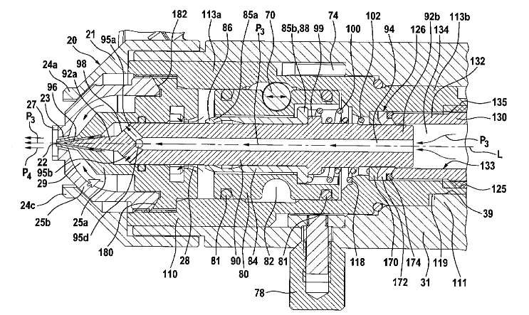
The Figure illustrates a spray device with a valve seat (22) located downstream of movable valve element (90), wherein needle (90) comprises an internal channel (94).
This place covers:
Illustrative example of subject matter classified in this place:
The Figure illustrates a deflector on a valve body (80), which acts as both a valve and a deflector.
Attention is drawn to the following places, which may be of interest for search:
Nozzles, spray heads or other outlets designed to control volume of flow with fixed deflectors | |
Nozzles, spray heads or other outlets designed to control volume of flow, in which the control is effected by relative coaxial longitudinal movement of the controlling element and the spray head, and in which the controlling element comprises both a lift valve and a deflector |
This place covers:
Illustrative example of subject matter classified in this place:
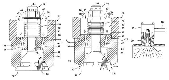
The Figure illustrates a movable controlling element (18) comprising a lift valve (26) and a deflector (29) separated from the lift valve (26), wherein the deflector (29) itself does not act as a valve.
Attention is drawn to the following places, which may be of interest for search:
Controlling elements comprising a deflector acting as a valve in co-operation with the outlet orifice |
This place covers:
Illustrative example of subject matter classified in this place:
1a.
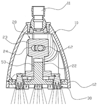
Figure 1a illustrates three or more valve bodies (30).
1b.

Figure 1b illustrates a valve body (30) which is provided with grooves (33).
1c.
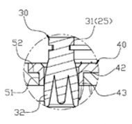
Figure 1c illustrates the movement of each valve body (30) within a corresponding outlet orifice (42) that controls the amount of water flowing out of the outlet orifice (42).
This place covers:
Illustrative example of subject matter classified in this place:
1a.
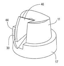
Figure 1a illustrates that the movement of one or both vanes (44, 46) reduce the slotted outlet dimension of outlet opening (30).
1b.
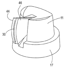
Figure 1b illustrates that the movement of one or both vanes (44, 46) enlarge the slotted outlet dimension of outlet opening (30).
This place does not cover:
Nozzles, spray heads or other outlets designed to control volume of flow, the control being effected by relative coaxial longitudinal movement of the controlling element and the spray head |
This place covers:
Illustrative example of subject matter classified in this place:
1a.
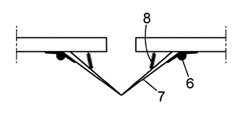
Figure 1a illustrates the closed position of an outlet opening (7) lacking fluid pressure.
1b.
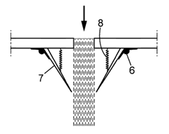
Figure 1b illustrates an outlet opening (7) actuated by the pressure of the fluid to be sprayed through the opening (7) with the fluid flowing downward though the opening (7), as indicated by the arrow.
This place does not cover:
Single-unit outlet valves actuated by the pressure of the fluid to be sprayed |
This place covers:
Illustrative example of subject matter classified in this place:
The Figure illustrates a rotatable outer sleeve (9) closing hole (8), in which the outer sleeve (9) has a first hole (10) that can be located in alignment with a second hole (8) in an inner member (1) by turning the rotatable outer sleeve (9) suitably.
This place covers:
Illustrative example of subject matter classified in this place:
1a.
1b.
1c.
Figures 1a, 1b and 1c illustrate fins (20, 30) acting as flow straightening means to reduce turbulence.
Examples of places where the subject matter of this place is covered when specially adapted, used for a particular purpose, or incorporated in a larger system:
Fuel-injectors provided with means to impart a whirling motion to fuel for combustion engines | |
Burners using a direct spraying action obtained by centrifugal action | |
Burner nozzles provided with swirl means |
This place covers:
Illustrative example of subject matter classified in this place:
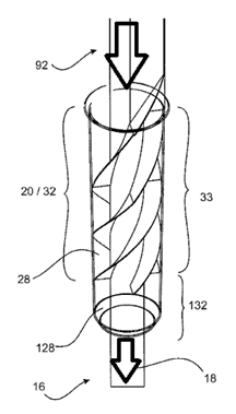
The Figure illustrates an insert inside of a tube (28) that imparts swirl upstream of a swirl chamber.
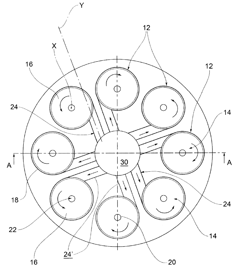
This place covers:
Illustrative example of subject matter classified in this place:
1a.
1b.
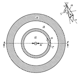
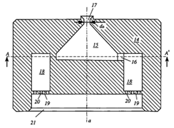
Figures 1a and 1b illustrate channels (16) emerging in a swirl chamber (15) perpendicularly to an axis "a" in Figure 1b.
This place does not cover:
Channels that are formed at the interface of cooperating elements and the interface is a plane perpendicular to the outlet axis |
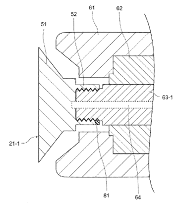
This place covers:
Illustrative example of subject matter classified in this place:
1a.
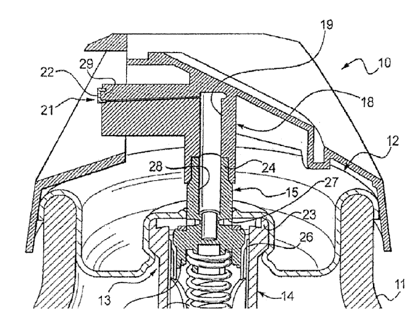
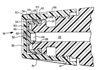
Figure 1a illustrates channels formed at the planar interface between end wall (29) and insert (21).
1b.
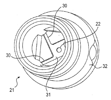
Figure 1b illustrates channels (30) formed at the planar interface between end wall and insert (21).
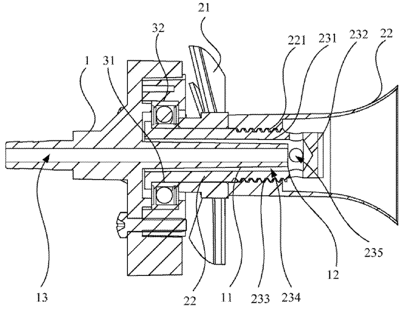
This place covers:
Illustrative example of subject matter classified in this place:
1a.
1b.
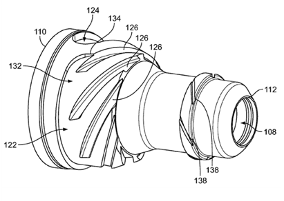
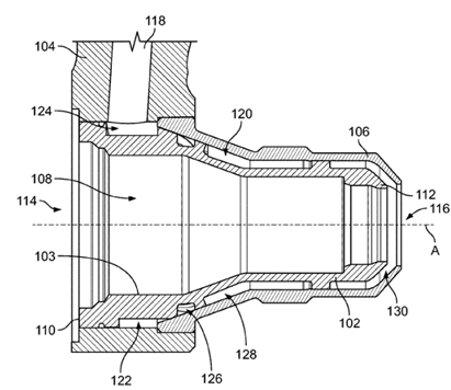
Figures 1a and 1b illustrate channels (126) formed at the conical interface between outer member (106) and inner member (102).
This place covers:
Illustrative example of subject matter classified in this place:
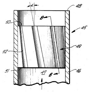
The Figure illustrates channels (52) formed at the cylinder interface between housing (46) and plug (49) that shares the same axis as the outlet (end of 48).
This place covers:
Illustrative example of subject matter classified in this place:
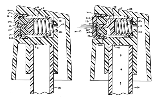
1a.
1b.
Figures 1a and 1b illustrate a cooperative element (having grooves 50) being movable in response to fluid pressure.
This place covers:
Illustrative example of subject matter classified in this place:
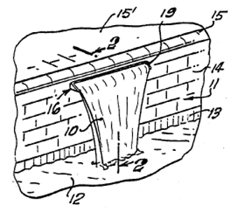
The Figure illustrates channels (24) extending from inside (30) to the outside of a swirl plate for imparting a swirling motion within swirl chambers (14).
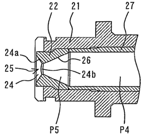
This place covers:
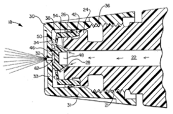
Illustrative example of subject matter classified in this place:
The Figure illustrates a controlling means (valve 19), which controls a fluid that is entering or leaving a swirl chamber (24a) in response to the fluid (via fluid moving valve 19).
This place covers:
Illustrative example of subject matter classified in this place:
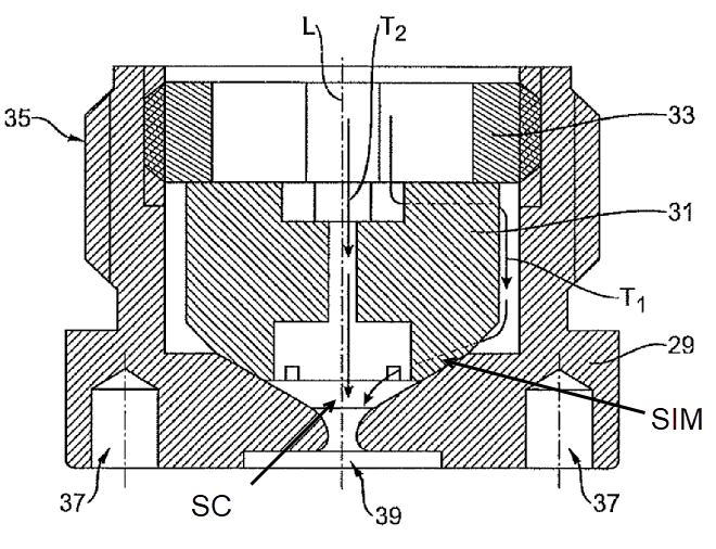
The Figure illustrates a first path (T1) and a second path (T2) reaching swirl chamber (SC).
This place covers:
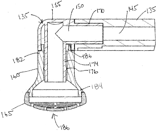
Illustrative example of subject matter classified in this place:
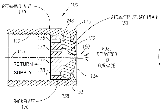
The Figure illustrates channels (172, 174) that bypass the swirl imparting means (248, 238) from a swirl chamber (132) back to a supply flow (178) toward the right side and the return flow (174). Further aspects include: fuel delivered to furnace toward the right side beyond the fuel outlet (150), atomizer spray plate (130), retaining nut (110) and backplate (170).
This place covers:
Illustrative example of subject matter classified in this place:
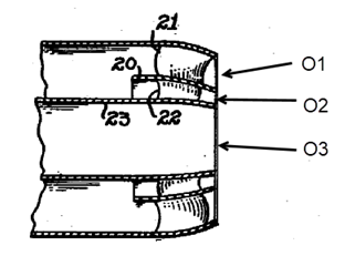
The Figure illustrates a spray nozzle having three concentric outlets (O1, O2, O3) dispensing a swirling discharge from vanes (21, 22).
This place covers:
Illustrative example of subject matter classified in this place:
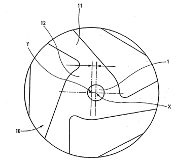
The Figure illustrates an outlet (1) on a different axis than that of a swirl chamber (12).
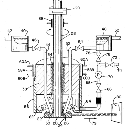
This place covers:
Nozzles, spray heads or other outlets for discharging by overflow. For example, an outlet having a trough, open tank or holder type fluid handling means, which depends for its distributing function upon accumulated fluid running over a top or an edge of a retaining wall or through a depression or notch in a wall.
Illustrative example of subject matter classified in this place:
1a.
1b.
Figures 1a and 1b illustrate an outlet (19) discharging by overflow of water (from 21).
Spray heads classified in this place are provided with moving elements, whereas spray heads classified in group B05B 13/04 move in their entirety, relative to an object to be sprayed.
Illustrative examples of subject matter classified in this place compared to subject matter classified in group B05B 13/04:
1.
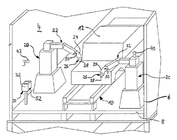
Figure 1 illustrates a moving spray head (24) provided with a rotary bell cup (28) that is classified in group B05B 3/1014 by itself. Spray head (24) is further moved by a supporting robot (20) having an articulated arm to paint work (12) that is classified in group B05B 13/0431.
2.
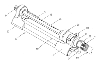
Figure 2 illustrates a sprinkler having an oscillating arm (40) that is classified in group B05B 3/0438. Since the sprinkler lies in its entirety on the ground and does not move during operation, this sprinkler shall not be classified in group B05B 13/04.
Examples of places where the subject matter of this place is covered when specially adapted, used for a particular purpose, or incorporated in a larger system:
Washing or rinsing machines for crockery or tableware with movably-mounted spraying devices |
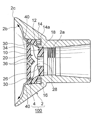
This place covers:
Illustrative example of subject matter classified in this place:
The Figure illustrates shaping air (10) used as cooling air passing in ducts (20) to cool a rotor (13) and a stator (12).
This place covers:
Illustrative example of subject matter classified in this place:
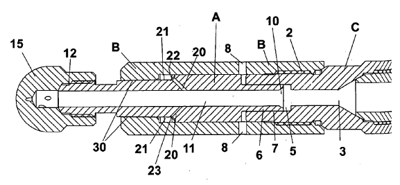
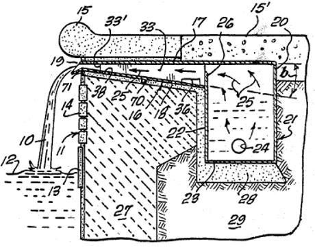
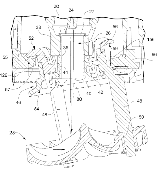
The Figure illustrates an annular interface (7) in between a housing (C) and shaft (A) sized so as to minimize leakage while still allowing rotation of the shaft (A) with a slight cushion of liquid. Passages (20) enable liquid to enter chamber (21). Liquid pressure upon surface (23) creates a thrust force capable of countering the input force applied by the liquid onto an inlet end (6).
This place covers:
Illustrative example of subject matter classified in this place:
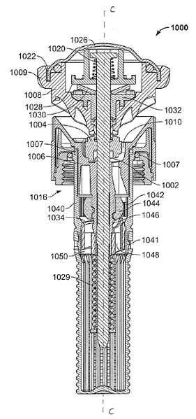
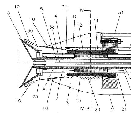
The Figure illustrates a frustoconical brake pad (1030) being part of a brake disposed in deflector (1008), which maintains rotation of the deflector (1008) at a relatively constant speed irrespective of flow-rate, fluid pressure or temperature. The brake includes brake pad (1030) sandwiched in between a friction disk (1028, above brake pad 1030) and seal retainer (1032, below brake pad 1030). Friction disk (1028) is held relatively stationary by shaft (1020), while seal retainer (1032) rotates with the deflector (1008). During operation of nozzle (1000), seal retainer (1032) is urged upwardly against brake pad (1030), which results in a variable frictional resistance that maintains a relatively constant rotational speed of deflector (1008), irrespective of the rate of fluid flow, fluid pressure or operating temperature.
This place covers:
Illustrative example of subject matter classified in this place:
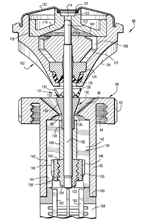
The Figure illustrates how rotation of deflector (102) will be slowed by the viscous shearing of fluid (110) in between stator (124 on central shaft 112) and the deflector wall forming a chamber (108).
This place covers:
Illustrative example of subject matter classified in this place:
The Figure illustrates magnets (5) being used to dampen rotation of distributor (2).
This place covers:
Illustrative example of subject matter classified in this place:
1a.
1b.
1c.
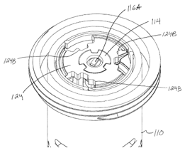
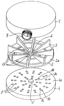
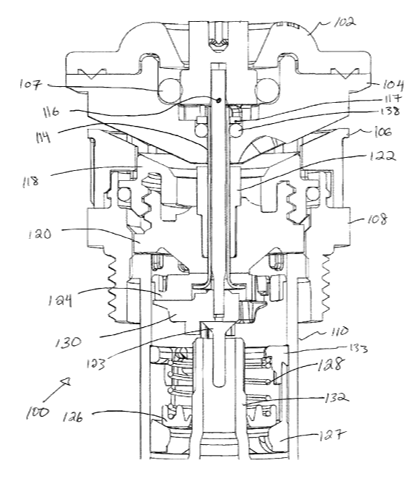
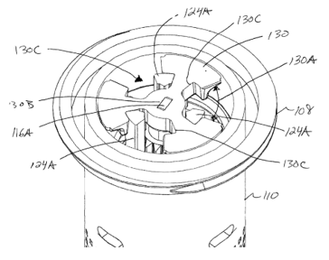
Figures 1a, 1b and 1c illustrate a sprinkler (100). The water flow through sprinkler (100) is adjusted by aligning spaces or apertures (130A) formed by throttle plate (130) with apertures (124B) in drive plate (124). Therefore, increasing alignment of apertures (130A, 124B) increases the flow out of sprinkler (100), while decreasing alignment of apertures (130A, 124B) decreases the flow. Throttle plate (130) is located below drive plate (124) and includes centre aperture (130B that engages with mating lower end (116A) of flow adjustment shaft (116). In this respect, rotating flow adjustment shaft (116) also rotates throttle plate (130) relative to drive plate (124). Throttle plate (130) is frictionally engaged to the bottom of drive plate (124), rotating throttle plate (130) with drive plate (124). Additionally, the flow of water through sprinkler (100) may cause slight movement and pressure of throttle plate (130) upwards against drive plate (124), further increasing friction. The frictional or clutching force between throttle plate (130) and drive plate (124) is such that it can be overcome when the user adjusts flow adjustment member (112) and therefore the flow of sprinkler (100).
This place covers:
Illustrative example of subject matter classified in this place:
The Figure illustrates a water deflection plate (28) carried by a starter sleeve (44) and a hanger tube (26) for wobbling or nutating motion.
This place does not cover:
Rotor nozzles |
This place covers:
Illustrative example of subject matter classified in this place:
The Figure illustrates an electric motor (8) connected to a reduction gear (6) that is in mesh with a tooth wheel (20). Operation of the motor (8) rotates part (22) and nozzle (12).
This place does not cover:
Electric spraying discharge apparatus characterised by having rotary outlet or deflecting elements |
This place covers:
Illustrative example of subject matter classified in this place:
The Figure illustrates a deflecting rotating element (27).
This place does not cover:
Spraying or sprinkling apparatus with moving outlet elements or moving deflecting elements driven by the liquid or other fluent material discharged, comprising a liquid driven rotor, actuated downstream of the outlet elements, and the liquid driven rotor being a deflecting rotating element | |
Spraying or sprinkling apparatus with moving outlet elements or moving deflecting elements discharging over substantially the whole periphery of the rotating member |
This place covers:
Illustrative example of subject matter classified in this place:
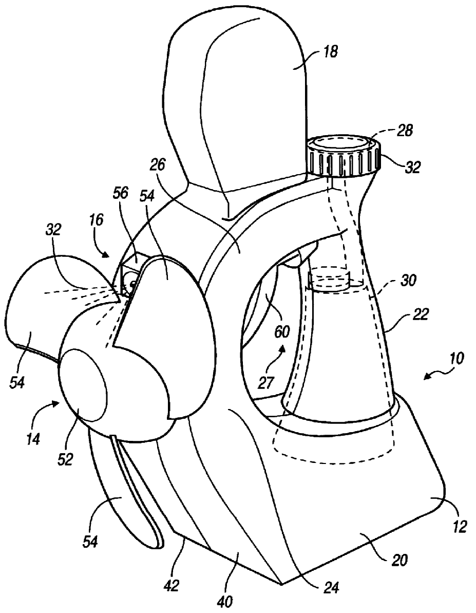
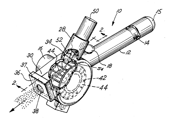
The Figure illustrates a fan assembly (14) having blades (54) that deflect a stream (32).
This place covers:
Illustrative examples of subject matter classified in this place:
1a.
1b.
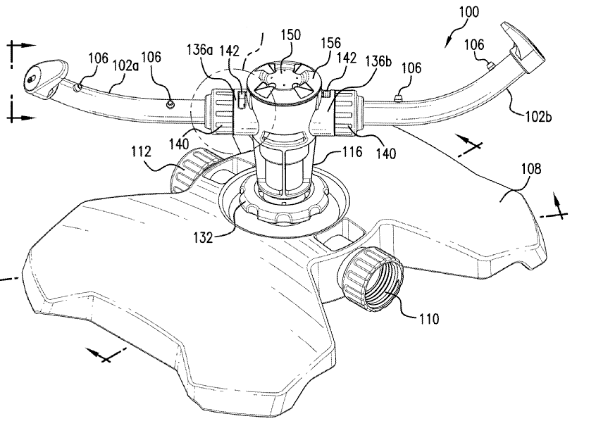
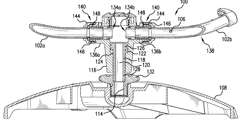
Figures 1a and 1b illustrate rotating jet arms (102a, 102b) of a sprinkler adjusting an angle of inclination (104) of nozzles (106), which is inversely proportional to the area of coverage of sprinkler (100), the rotation being driven by reaction of the water discharged nozzles (106) on the respective nozzle body.
2.
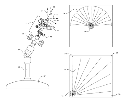
Figure 2 illustrates the angular position of the outlet element (20) that allows for the rotating impact sprinkler to spray noncircular areas.
3.
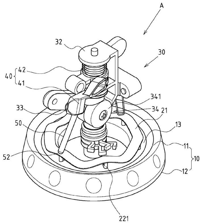
Figure 3 illustrates a percussive sprinkler (A) having a main body (30) that is rotated with vertical variation, a sprinkler head driving rod (50) shifting vertically along a circumferential path on a driving rod retaining surface (21, shaped for vertical variation during rotation) of an adjusting ring, so that the sprinkler head (33) is driven to swing vertically with changes of the discharge angle.
This place does not cover:
Spraying or sprinkling apparatus with moving outlet elements or moving deflecting elements driven by the liquid or other fluent material discharged, comprising a liquid driven rotor with automatic means for regulating the discharged jet relative to the angular position of the outlet elements or to the direction of rotation of the outlet elements |
This place covers:
Illustrative examples of subject matter classified in this place:
1.
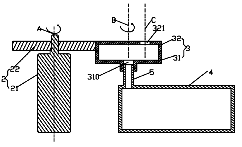
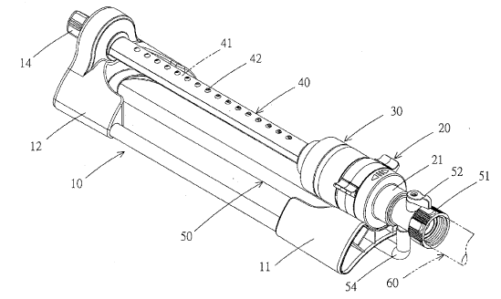
Figure 1 illustrates a rotational joint between a fixed tube (5) that contains a rotary bearing on the end connected to rotating tube (310).
2.
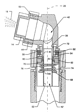
Figure 2 illustrates fluid passing from (42') into (42) to be sprayed (18), passing axially from the bottom member to that of the nozzle member (14), both elements being jointed to one another via bearing sleeve (40) so that the spray (18) sweeps over a surface due to rotation about central axis (26).
Attention is drawn to the following places, which may be of interest for search:
Pipes having adjustable joints with axial fluid passages in general |
This place covers:
Illustrative example of subject matter classified in this place:
The Figure illustrates rotational joints of arms (102a, 102b) having inner radial fluid passages extending from the central fluid passage (120) to the outlets of holes (106).
Attention is drawn to the following places, which may be of interest for search:
Pipes having adjustable joints with radial fluid passages in general |
This place covers:
Illustrative example of subject matter classified in this place:
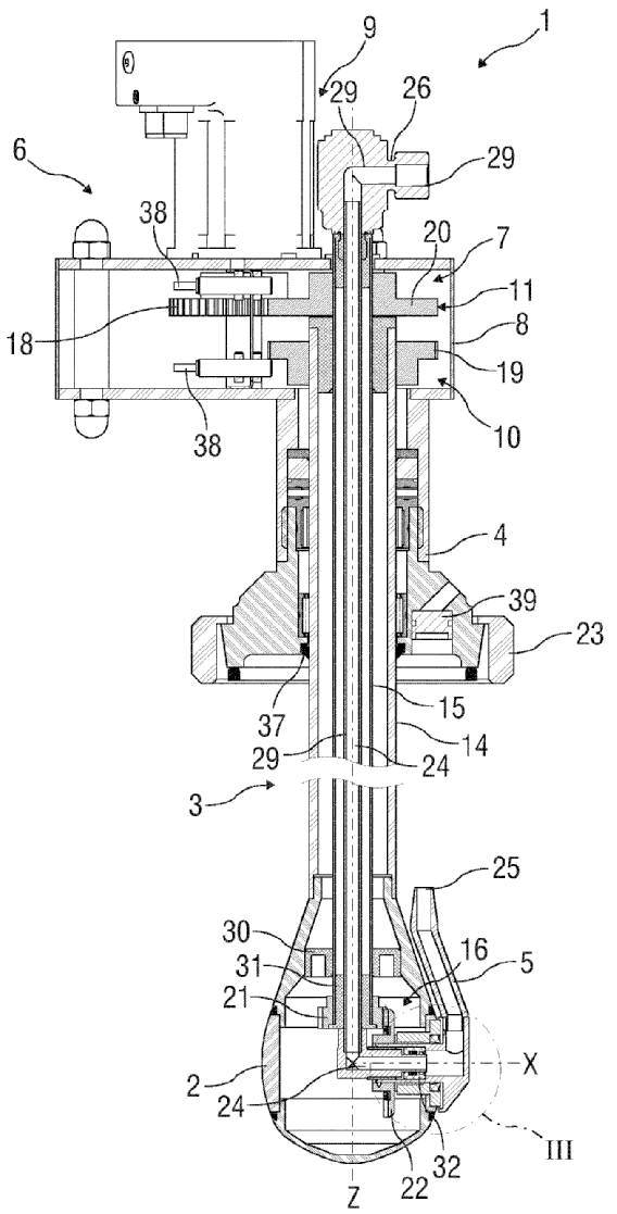
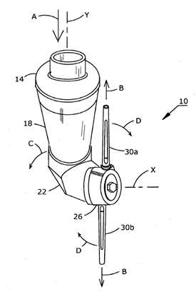
The Figure illustrates a nozzle (25) rotating about both axes (X) and (Z).
This place does not cover:
Spraying or sprinkling apparatus with rotating outlet elements driven by the liquid or other fluent material discharged, the movement of the outlet elements being a combination of two movements, one being rotational | |
Spraying or sprinkling apparatus with rotating elements, driven by the liquid or other fluent material discharged by jet reaction, the movement of the outlet elements being a combination of two movements, one being rotational |
This place covers:
Illustrative examples of subject matter classified in this place:
1.
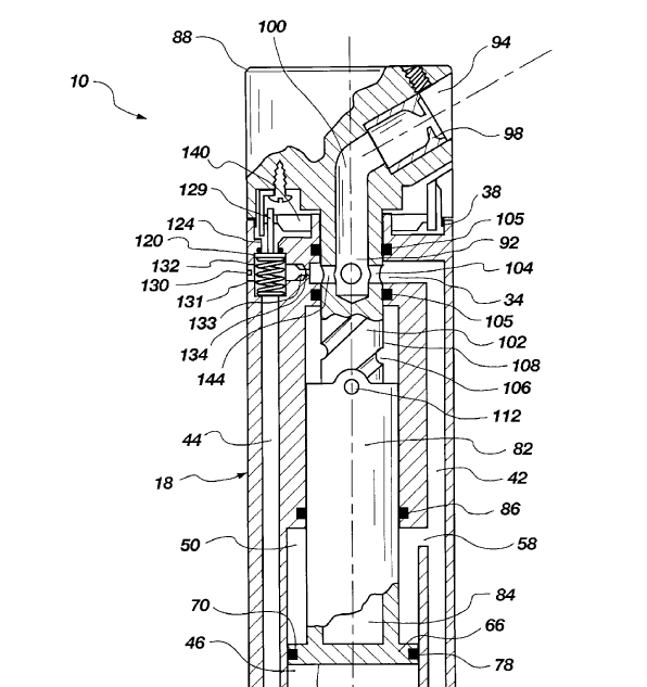
Figure 1 illustrates a sprinkler device (10) having a helical track (106) and a tracking element (112) coupled between a reciprocating piston (66) and a rotating head or nozzle (98) to convert the reciprocal linear motion of the piston to rotation motion of the head or nozzle.
2.
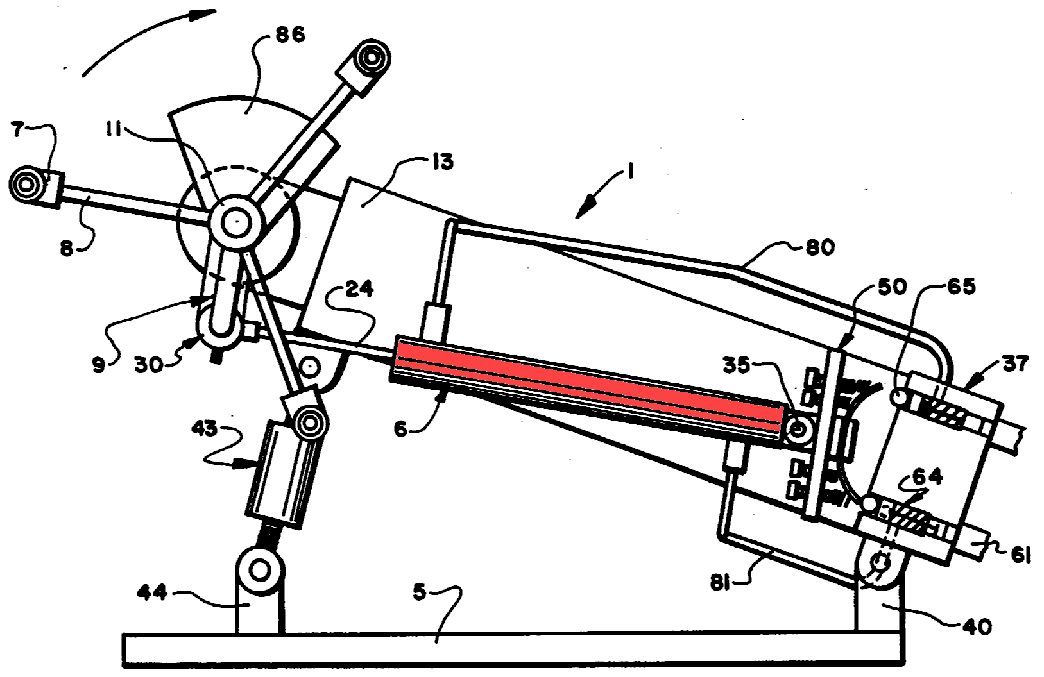
Figure 2 illustrates rotating nozzles (7) actuated by piston (6).
This place covers:
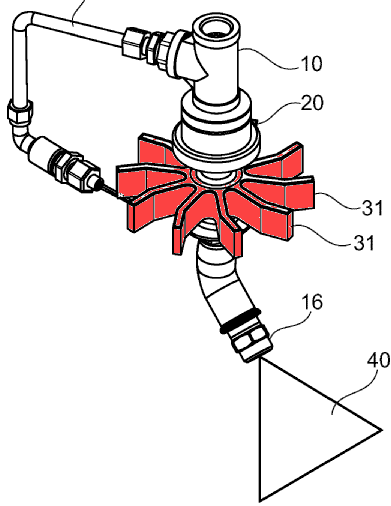
Illustrative example of subject matter classified in this place:
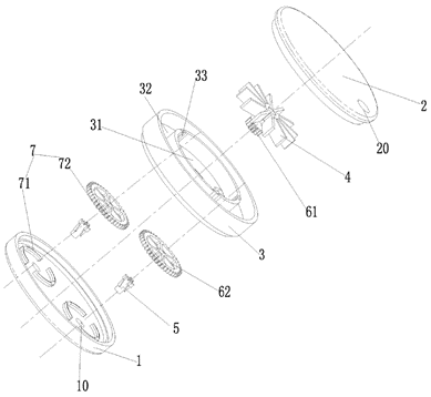
The Figure illustrates nozzles (5) rotated by rotor (4) via gears (61) and (62,72), wherein rotor (4) is driven by water.
In patent documents, the following words/expressions are often used as synonyms:
- "rotor", "impeller", "turbine" and "rotator"
This place covers:
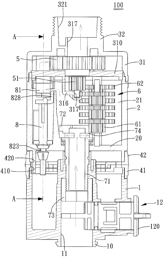
Illustrative example of subject matter classified in this place:
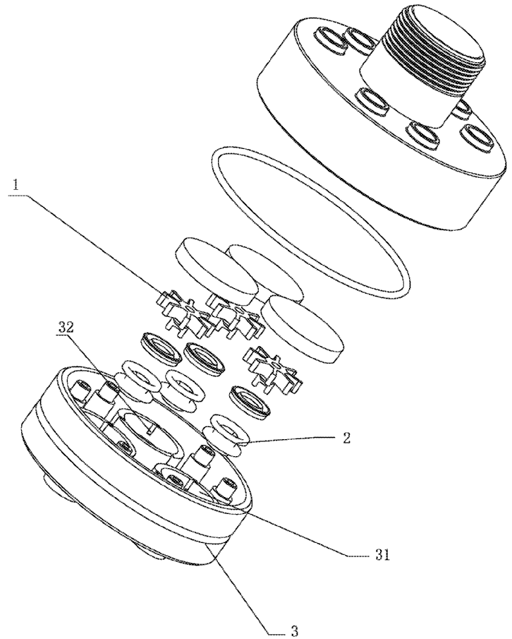
The Figure illustrates several rotors (1) driven by water, wherein each rotor (1) actuates the rotation of a corresponding nozzle (2).
This place covers:
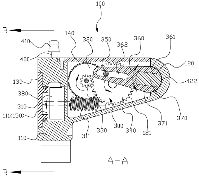
Illustrative example of subject matter classified in this place:
1a.
1b.
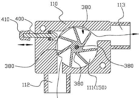
Figures 1a and 1b illustrate a stop (410) to disable rotation of rotor (380), wherein rotation of rotor (380, in Figure 1b) drives rotation of nozzle (113, in Figure 1a).
This place covers:
Illustrative examples of subject matter classified in this place:
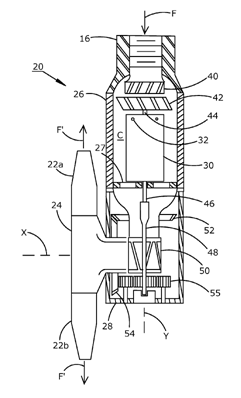
The Figure illustrates rotation of a rotor (42) not being parallel to the rotation axis of an outlet element (22a, 22b, 24).
This place covers:
Illustrative example of subject matter classified in this place:
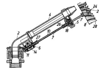
The Figure illustrates a rotor (8) actuated downstream of nozzle (4) outlet, wherein the rotor (8) actuates rotation of the nozzle (4).
This place covers:
Illustrative example of subject matter classified in this place:
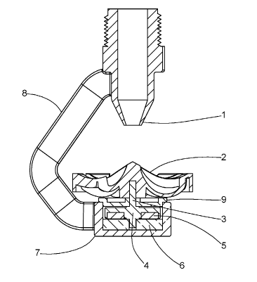
The Figure illustrates a liquid driven rotor (2) that is a deflecting rotating element.
This place covers:
Illustrative example of subject matter classified in this place:
The Figure illustrates a rotor (31) directly attached on the outside of a nozzle (16) supply.
This place covers:
Nozzles consisting of an element having an upstream part rotated by the liquid flow and a downstream part connected to the apparatus by a universal joint.
Illustrative example of subject matter classified in this place:
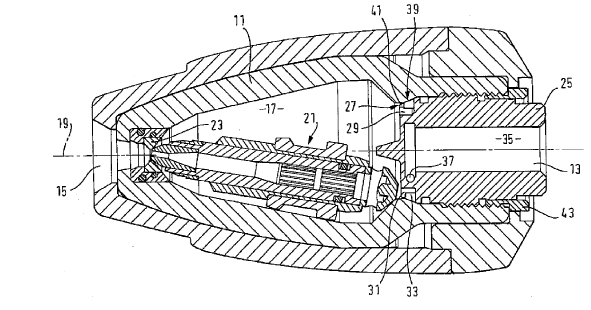
The Figure illustrates a rotor nozzle having an upstream part rotated inside a housing (11) and a downstream part connected to universal joint (23).
This place covers:
Illustrative example of subject matter classified in this place:
1a.
1b.
Figures 1a and 1b illustrate rotation of a rotor (380) that causes oscillation of a nozzle (113).
This place does not cover:
Spraying or sprinkling apparatus with rotating outlet elements driven by the liquid or other fluent material discharged, the movement of the outlet elements being a combination of two movements, one being rotational |
This place covers:
Illustrative example of subject matter classified in this place:
1a.
1b.
Figures 1a and 1b illustrate that when water reaches an impeller (5) through inlet (313), the water flow drives the impeller (5) in one rotational direction and when water reaches the impeller (5) through inlet (314) the water flow drives the impeller (5) in the other rotational direction.
This place covers:
Illustrative example of subject matter classified in this place:
The Figure illustrates a tubular element (40) that has several outlets (42) and oscillates around an axis (axis of 40) parallel to the tubular element (40).
This place covers:
Illustrative example of subject matter classified in this place:
1a.
1b.
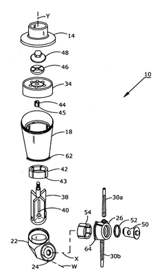
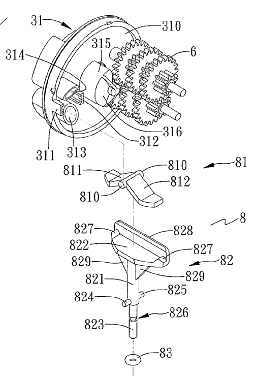
Figures 1a and 1b illustrate nozzles (30a, 30b) rotating about both axes (X) and (Y), i.e. a combination of two movements, at least one being rotational, wherein both rotations are actuated by a rotor (38) driven by a cleaning fluid.
This place covers:
Illustrative example of subject matter classified in this place:
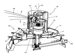
The Figure illustrates a rotating irrigating nozzle (DU) having an outlet opening area that is varied according to a curved tread (LF), wherein rotation of the nozzle (DU) is actuated by a rotor within a driving housing (AG) the rotor being driven by water.
This place does not cover:
Spraying or sprinkling apparatus with rotating outlet elements driven by the liquid or other fluent material discharged, the movement of the outlet elements being a combination of two movements, one being rotational |
This place covers:
Illustrative example of subject matter classified in this place:
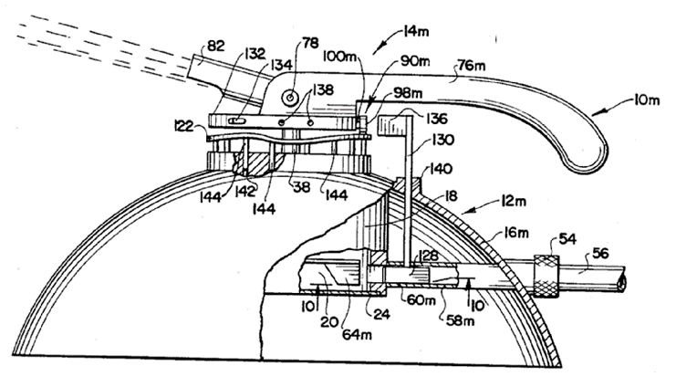
The Figure illustrates a lawn sprinkler, when roller (98m) rolls along the top of cam track (122), a rotary nozzle (82) raises and lowers about pivot pin (78), wherein rotation of the nozzle (82) about a vertical axis is actuated by rotor (64m), driven by water.
This place covers:
Illustrative example of subject matter classified in this place:
The Figure illustrates how the spray jet discharged from the outlet (4) actuates a movable deflector (11) which is successively moved out of the jet-by-jet action and brought back into the jet by the action of the spring (10).
In patent documents, the following words/expressions are often used as synonyms:
- "impact sprinkler", hammer sprinkler", "impulse type sprinkler" and "percussive sprinkler"
This place covers:
Illustrative example of subject matter classified in this place:
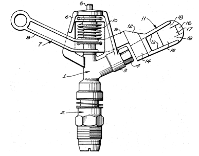
The Figure illustrates an impact sprinkler (12) in which the rotation of outlet element (13) is reversed by the abutments (as stops extending outward on both sides from the outside of the supply pipe).
This place covers:
Illustrative example of subject matter classified in this place:
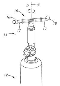
The Figure illustrates a rotating portion including two arms (17) and two nozzles (18), each nozzle attached to an end of a respective arm (17). Nozzles (18) are adapted to discharge liquid received from device (12) to the outside environment along directions that form moments of force urging the rotating portion to rotate in a direction (R) about an axis (X).
Examples of places where the subject matter of this place is covered when specially adapted, used for a particular purpose, or incorporated in a larger system:
Washing or rinsing machines for crockery or tableware with rotary spraying devices moved by means of the sprays |
This place covers:
Illustrative example of subject matter classified in this place:
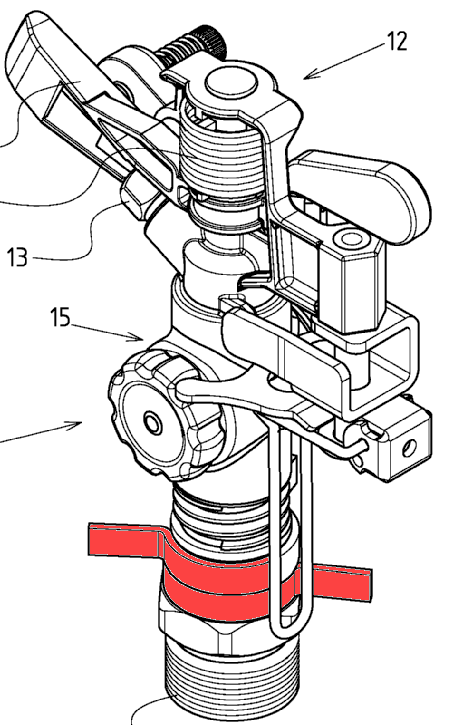
The Figure illustrates a deflector (120) that creates a tangential component of the jet as indicated by the lines leaving the deflector, this tangential component causing sprinkler (100) to rotate.
This place covers:
Illustrative example of subject matter classified in this place:
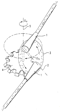
The Figure illustrates nozzles (1), whose movement is a combination of two rotations, i.e. a combination of two movements, at least one being rotational, the rotations being driven by reaction of water discharged by nozzles (1) on the respective nozzle body.
This place covers:
Illustrative examples of subject matter classified in this place:
1.
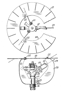
Figure 1 illustrates a rotary sprinkler (10) in association with a stationary deflecting element (18), wherein individual segments (17) on the annular disc (18) may be deformed to restrict the range of the stream of water in any desired direction.
2a.
2b.
Figures 2a and 2b illustrate a rotary outlet element (30) and rotary deflecting elements (50), both in association with stationary outlets (10).
This place covers:
Illustrative example of subject matter classified in this place:
The Figure illustrates a rotary spraying disk (5) as a deflecting element, in association with stationary outlets (8).
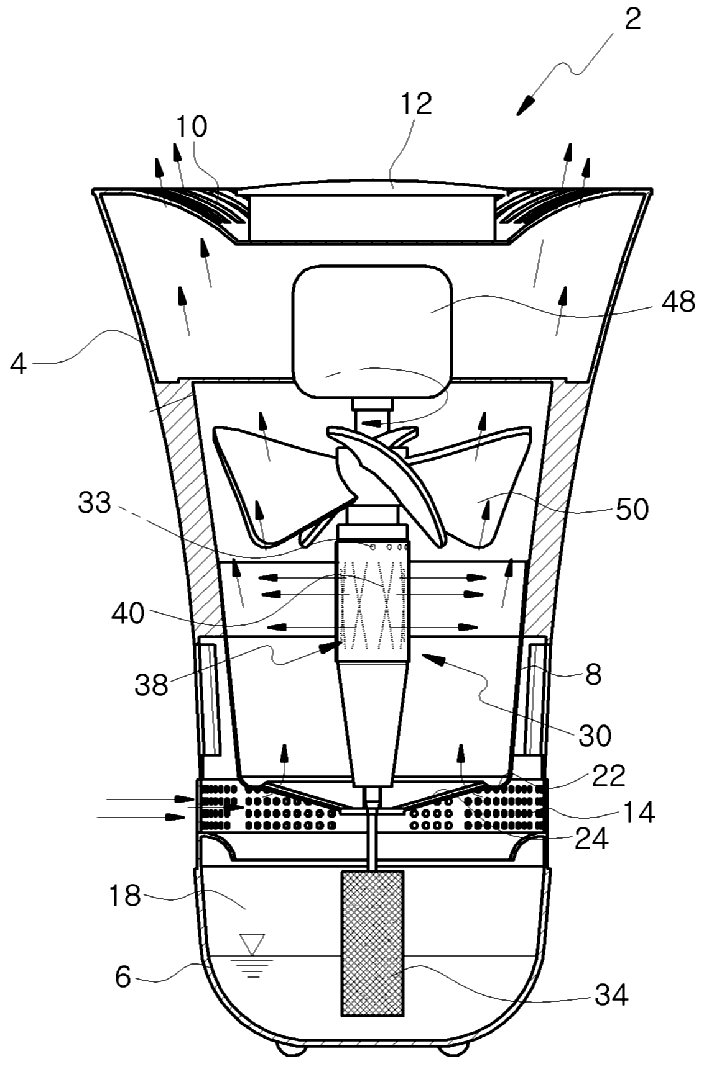
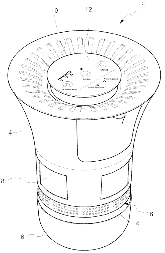
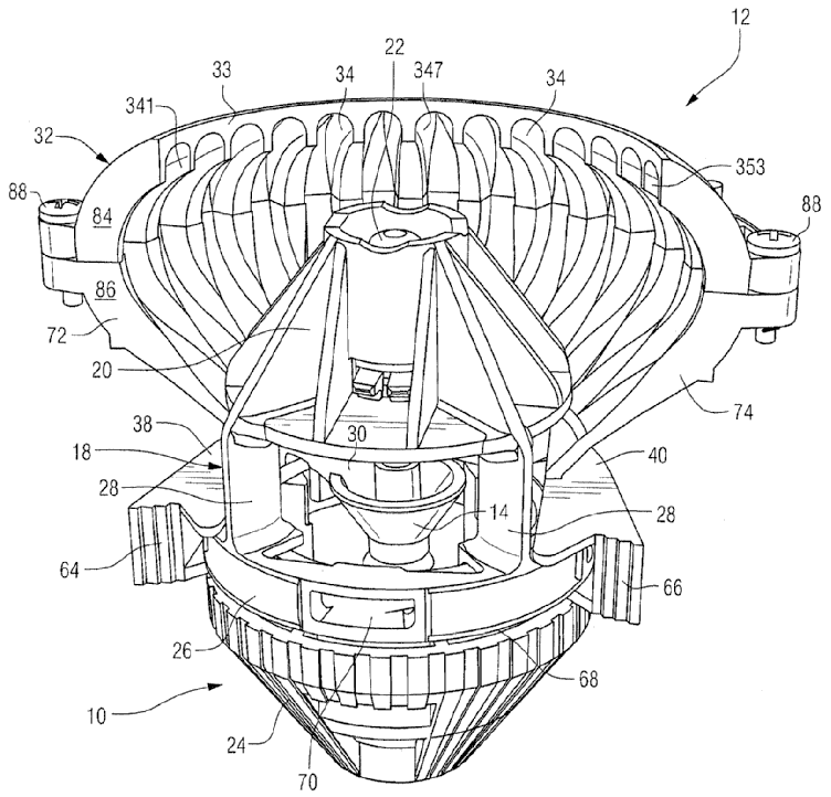
Attention is drawn to the following places, which may be of interest for search:
Air-humidification by forming water dispersions in the air using rotating elements |
This place covers:
Illustrative example of subject matter classified in this place:
The Figure illustrates a stationary fixed deflector (12) in association with a rotary sprinkler (10), wherein a deflector (12) limits distribution of a stream emitted by the sprinkler (10) to less than the 360-degree circle pattern that would otherwise be irrigated by the stream.
This place covers:
Illustrative example of subject matter classified in this place:
The Figure illustrates an air brush (10), wherein spraying is effected by centrifugal forces from rotary deflecting elements (42), in association with sectorial stationary deflecting element (30).
This place does not cover:
Spraying or sprinkling apparatus with rotating elements in association with stationary outlet or deflecting elements, the spraying being effected by centrifugal forces |
Attention is drawn to the following places, which may be of interest for search:
Making metallic powder or suspensions thereof by spraying using centrifugal force |
This place covers:
Illustrative example of subject matter classified in this place:
The Figure illustrates a cup-shaped spray head (23) being part of a rotary nozzle.
This place covers:
Illustrative example of subject matter classified in this place:
The Figure illustrates a rotary spraying plate provided with individual passages (30).
This place covers:
Illustrative example of subject matter classified in this place:
The Figure illustrates an insert (7) that forms an individual passage at the periphery of the rotating member (4).
This place covers:
Illustrative example of subject matter classified in this place:
The Figure illustrates means for connecting a rotating spray head (51) to its driving shaft (64) being reversible (a threaded connection allows the head to be screwed on and off).
This place covers:
Illustrative example of subject matter classified in this place:
The Figure illustrates a rotary cup-shaped spray head (22) associated with fan blades (21).
This place covers:
Illustrative example of subject matter classified in this place:
The Figure illustrates two outlets (44) and (52), which supply two liquids (42) and (50) to a rotating element (20).
This place covers:
Illustrative example of subject matter classified in this place:
The Figure illustrates a fluid sprayed as axially supplied to rotating member (2) from a hollow rotating shaft (tube that affixes to 2a).
This place covers:
Illustrative example of subject matter classified in this place:
1a.
1b.
Figures 1a and 1b illustrate two rotating members (20) and (38) that rotate in opposite directions.
This place covers:
Illustrative example of subject matter classified in this place:
The Figure illustrates a gas being supplied from a compressed air source (60) out of a sleeve (40) to shape the fluid being discharged from a rotary bell-shaped disc (8).
Attention is drawn to the following places, which may be of interest for search:
Means for supplying shaping gas associated with rotary outlet or deflecting elements of apparatus spraying liquids or other fluent materials by electric or electrostatic means | |
Means for supplying shaping gas associated with spraying apparatuses without any moving outlet or deflecting elements |
This place covers:
Illustrative example of subject matter classified in this place:
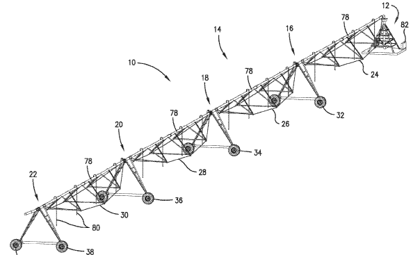
The Figure illustrates a spray boom (10, system) rotating about axis (12) by means independent of the liquid or material discharged, wheels (32, 34, 36, 38) having integrated motors rotating them independently from the fluid in the system.
Examples of places where the subject matter of this place is covered when specially adapted, used for a particular purpose, or incorporated in a larger system:
Watering arrangements movable around a pivot centre for agricultural watering of gardens, fields, sports grounds or the like | |
Special adaptations or arrangements of liquid-spraying apparatus for agricultural uses, e.g. spray booms |
This place covers:
Illustrative example of subject matter classified in this place:
1a.
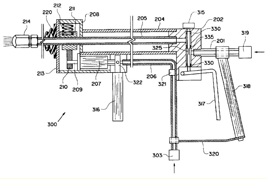
1b.
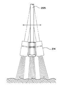
Figures 1a and 1b illustrate an oscillating nozzle (214), the oscillation being driven by a motor (207).
This place covers:
Illustrative example of subject matter classified in this place:
The Figure illustrates a fluid driving rotation of turbine (105) that actuates the movement of rocker assembly (200) of nozzle assembly (100), wherein rotation of the turbine (105) is converted into an oscillatory, back-and-forth linear motion of the rocker assembly (200).
This place does not cover:
Spraying or sprinkling apparatus with rotating outlet elements, comprising a liquid driven rotor wherein rotation of an outlet element is reversible | |
Spraying or sprinkling apparatus with rotating outlet elements, which are rotated by a deflecting element being successively moved into the discharged jet by the action of a biasing means and out of the discharged jet by the discharged jet with the rotation of the outlet elements being reversible |
This place covers:
Illustrative example of subject matter classified in this place:
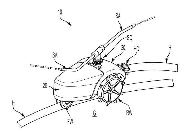
The Figure illustrates a mobile sprinkler (10) moving along a track (H).
This place does not cover:
Watering arrangements making use of movable installations on wheels or the like |
Apparatus of the B05B 7/00 type which are to be carried on or by a person, e.g. by hand, and which have a container are classified in B05B 7/2405+, B05B 7/244+.
B05B 11/00 takes precedence.
Apparatus of the B05B 9/00 type which are to be carried on or by a person, e.g. by hand, and have a container being put under pressure are classified in B05B 9/0805+.
Apparatus of the B05B 9/00 type which are to be carried on or by a person, e.g. by hand, and have a container being put under pressure are classified in B05B 9/0805+.
B05B 11/00 takes precedence.
Apparatus of the B05B 7/00 type which are to be carried on or by a person, e.g. by hand, and which have a container are classified in B05B 7/2405+, B05B 7/244+.
Attention is drawn to the following places, which may be of interest for search:
Details or components, e.g. casings, bodies, of portable power-driven tools not particularly related to the operation performed |
This place covers:
Single-unit hand-held apparatus comprising a container and a dispensing nozzle attached thereto, in which flow of contents is produced by the muscular force of the operator at the moment of use.
The expression "Single-unit hand-held apparatus in which flow of contents is produced by the muscular force of the operator at the moment of use" is very important to properly define the border line with other areas of B05B as well as with other technical fields, e.g. B65D, A47K, F04B.
Single-unit hand-held apparatus in which there exists a possibility to accumulate permanently a certain pressure on the material, e.g. liquid, and wherein this pressure is used to discharge the material through the outlet are not classified in B05B 11/00 and sub-groups, but in B05B 9/0805 and subgroups or B05B 7/2402 and subgroups.
In apparatus classified in B05B 11/109 and subgroups, energy can be stored, e.g. in the form of a compressed spring. However, the stored energy does not generate permanent pressure on the material for discharging the latter. Only when the spring is released is the material pressurized in the pump chamber.
In apparatus classified in B05B 11/0041 and sub-groups, reservoirs containing the material may be permanently pressurized, e.g. by a follower piston pushed by a spring. However, this pressure is not used to discharge the material but only to feed the latter to a discharge device, e.g. a pump.
Aerosol containers are classified in B65D 83/14 and subgroups.
Apparatus of the B05B 7/00 type which are to be carried on or by a person, e.g. by hand, and which have a container are classified in B05B 7/2405, B05B 7/244 as well as their subgroups.
Apparatus of the B05B 9/00 type which are to be carried on or by a person, e.g. by hand, and have a container are classified in B05B 9/0805 and subgroups.
Attention is drawn to the following places, which may be of interest for search:
In this place, the following terms or expressions are used with the meaning indicated:
Content | liquid or other fluid material. |
Pump | A device comprising a chamber into which the material is first sucked from the container through an inlet, then delivered out of the chamber, e.g. sprayed, through an outlet. Inlet and outlet can be equipped with valves. |
Lift valve | A valve as defined in main group F16K 1/00, i.e. a cut-off device with closure members having at least a component of their opening and closing motion perpendicular to the closing faces. |
Gate valve or sliding valve | A valve as defined in main group F16K 3/00, i.e. cut-off device with closing members having a sliding movement along the seat for opening and closing. |
This place covers:
Membranes or pistons which are in contact with the contents inside the container.
Attention is drawn to the following places, which may be of interest for search:
Medical syringes, e.g. enemata | |
Syringes for bringing media into the body in a subcutaneous, intra-vascular or intramuscular way |
In this place, the following terms or expressions are used with the meaning indicated:
Follower | an element, e.g. piston, that is in contact with the material to be dispensed throughout the dispensing process. |
Attention is drawn to the following places, which may be of interest for search:
Containers adapted to be temporarily deformed by external pressure to expel contents |
This place covers:
Pumps drawing the contents from the container into a pump chamber inlet during a suction stroke and forcing the contents out of a pump chamber outlet into the dispensing nozzle during a dispensing stroke.
Attention is drawn to the following places, which may be of interest for search:
Controlling in general |
This place covers:
Means to restrict, limit the actuation by the user by limiting the movement of the controlling means.
Such restricting means are:
- locking means, e.g. for locking the valve in the open or close position
- stop means
Biasing means such as springs are not considered as means for restricting the movement.
If there is only one locking or stopping position, classification is made in B05B 12/0024 and subgroup.
Example of a locking means, with several positions:
Example of a stopping means, with several positions:

This place does not cover:
Nozzles, spray heads or other outlets designed to control volume of flow, the controlling element being actuated by the pressure of the fluid to be sprayed | |
Nozzles, spray heads or other outlets designed to control volume of flow in which a valve member forms part of the outlet opening, the valve member being actuated by the pressure of the fluid to be sprayed | |
Spraying apparatus for discharge of liquids or other fluent materials from two or more sources, e.g. of liquid and air, of powder and gas |
Attention is drawn to the following places, which may be of interest for search:
Control of flow in general | |
Control of fluid pressure in general |
Apparatus for changing colours are classified in B05B 12/14 and subgroups.
Attention is drawn to the following places, which may be of interest for search:
Blast of gas or vapour for spreading liquids already applied to a surface | |
Processes for applying liquids or other fluent materials to surfaces comprising directing or stopping the fluid to be coated with air |
Attention is drawn to the following places, which may be of interest for search:
Stencils | |
Use of means for protecting parts of a surface not to be coated in processes for applying liquids or other fluent materials to surfaces | |
Masking means used in electroplating |
Attention is drawn to the following places, which may be of interest for search:
Nozzles with integral means for shielding |
This place does not cover:
Processes for applying liquids or other fluent materials to surfaces in general |
Examples of places where the subject matter of this place is covered when specially adapted, used for a particular purpose, or incorporated in a larger system:
Watering arrangements making use of movable installations on wheels or the like |
Reference B05D is non-limiting in group B05B 13/00. CPC will be updated or corrected once this inconsistency is resolved in IPC.
Group B05B 13/00 is used to classify subject matter that is not fully covered by groups B05B 1/00 - B05B 11/00, so group B05B 13/00 can be used in addition to groups B05B 1/00 - B05B 11/00 when subject matter for B05B 1/00 - B05B 11/00 is also to be classified. For example, a means for supporting work can be classified in subgroup B05B 13/02 when it is used with a nozzle not requiring classification in group B05B 1/00, or a means for supporting work can be classified in subgroup B05B 13/02, in addition to classifying the nozzle used therewith in group B05B 1/00.
Means for supplying or discharging of liquid or other fluent material for applying liquids or other fluent materials to surfaces of objects or other work by spraying are covered by one of groups B05B 1/00 - B05B 12/00.
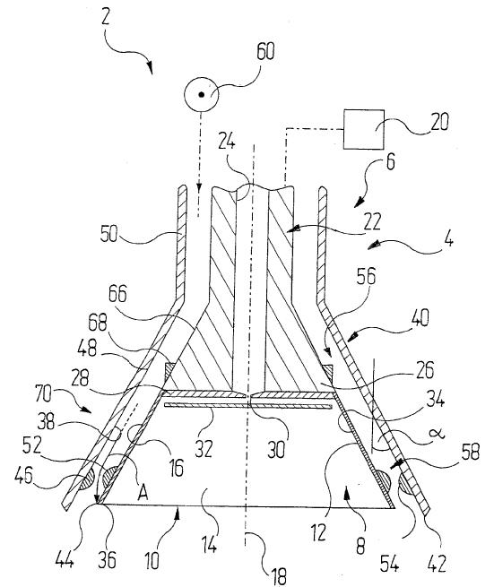
This place covers:
Machines or plants for inkjet coating onto work surfaces, e.g. by using nozzle heads provided with numerous closely spaced outlets. The resulting coating formed is a plain coating layer that is not patterned when applied onto the work surfaces.
Illustrative examples of subject matter classified in this place:
1a.
1b.

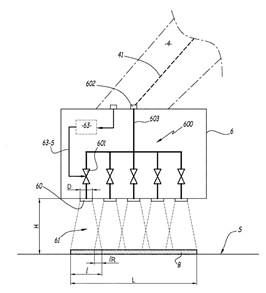
Figures 1a and 1b illustrate an inkjet coating head (6) provided with several spraying nozzles (60) aligned along one or several columns, or along one or more of several rows.
2.
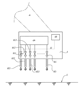
Figure 2 illustrates an inkjet coating head (6) provided with several nozzles (60.1, 60.2, 60.3 up to 60.i), each of the nozzles being configured to coat a surface (S) dropwise.
Subclass B41J and group B41J 3/4073 cover the projection of ink droplets for printing to form a meaningful pattern. Group B41J 11/0015 covers uniform or plain coating of copy material, e.g. paper, either before or after printing.
Attention is drawn to the following places, which may be of interest for search:
Selective printing on three-dimensional objects not being in sheet or web form |
In patent documents, the following words/expressions are often used as synonyms:
- "inkjet printing", "selective printing", "incremental printing", "drop on demand [DOD] printing", "non-impact printing [NPI]", "direct printing" and "drop discharge"
Attention is drawn to the following places, which may be of interest for search:
Manipulators for painting or coating |
This place does not cover:
Installation or apparatus for applying liquid or other fluent material to separate articles rotated during spraying operations |
Attention is drawn to the following places, which may be of interest for search:
Programme-controlled manipulators cooperating with conveyor means |
Attention is drawn to the following places, which may be of interest for search:
Cleaning devices for conveyors |
Attention is drawn to the following places, which may be of interest for search:
Movable or portable abrasive blasting machine with suction means for the abrasive and the waste material |
Attention is drawn to the following places, which may be of interest for search:
Paint detackifiers or coagulants used for the treatment of excess spraying materials |
Attention is drawn to the following places, which may be of interest for search:
Accessories applicable to other methods of applying liquids or other fluent materials to surfaces |
Attention is drawn to the following places, which may be of interest for search:
Dip tubes for aerosol containers |
Attention is drawn to the following places, which may be of interest for search:
Arrangements for preventing or detecting clogging or moistening of ink-jet nozzles | |
Detecting the presence of fluid at a leakage point |
Attention is drawn to the following places, which may be of interest for search:
Aerosol containers comprising alternative flow directions outlets |
Attention is drawn to the following places, which may be of interest for search:
Cleaning by the force of jets or sprays in general |
Attention is drawn to the following places, which may be of interest for search:
Joints in general |
Attention is drawn to the following places, which may be of interest for search:
Single-unit hand-held apparatus in which flow of contents is produced by the muscular force of the operator at the moment of use provided with a movable dispensing tube |
Attention is drawn to the following places, which may be of interest for search:
Nozzles for cleaning vehicle windscreens or optical devices materials to surfaces |
Attention is drawn to the following places, which may be of interest for search:
Enclosures, e.g. booths, for applying liquids or other fluent materials to surfaces |