CPC Definition - Subclass G09G
This place covers:
- Arrangements or circuits for processing control signals to achieve the display, e.g. for the reception, storage, regeneration, coding, decoding, format manipulation, addressing of control signals.
- Solution of problems of displays by means of their control, i.e. control for which features of a display are relevant, e.g. to compensate for varying pixel behaviour, which may lead to non-uniformity in the display.
- Improvements of the control of displays, i.e. where the functionality of controlling a display is relevant, e.g. selective brightness adaptation for lowering energy consumption of the display, possibly after image analysis.
- The visual effect in the indicating means using the static means may be produced by the generation of an image on a screen, e.g. indirectly by scanning an electron beam onto a luminescent screen, directly by controlled light sources, by projection of light from controlled light sources or light modulators onto characters, symbols, or elements thereof drawn on a support, or by electric, magnetic, or mechanic control of the parameters of light rays from an independent source.
Subclass G09G covers electronic control of display characterised by the display device itself, whereas it does not cover:
- electronic control characterized by the pictorial communication, e.g. television, which is covered by subclass H04N, or
- aspects like rastering an image onto the target resolution by a raster image processor (RIP), or image enhancement aspects like augmented reality, which are covered by subclass G06T.
Subclass G09G does not cover software modules, e.g. software driver modules for the display, or their interaction, such as interaction between software modules related to the display of windows or interaction between a software driver module for the display and the operating system which are covered by group G06F 9/00.
This place does not cover:
Microstructural devices comprising flexible or deformable elements, e.g. displays comprising elastic microtongues or membranes | |
Optical devices or arrangements using movable or deformable optical elements for controlling the intensity, colour, phase, polarisation or direction of light, e.g. switching, gating, modulating, e.g. displays based on interference in an adjustable optical cavity | |
Optical devices or arrangements using movable or deformable optical elements for controlling the intensity of light, e.g. displays based on the rotation of particles under the influence of an external field, e.g. twisting microsphere displays | |
Optical devices or arrangements using movable or deformable optical elements for controlling the direction of light, e.g. displays using a reflecting micromechanical device, like a MEMS mirror, DMD | |
Devices or arrangements for the control of the intensity, phase, polarisation or colour of light arriving from an independent light source based on liquid crystals, e.g. single liquid crystal display cells | |
Devices or arrangements for the control of the intensity, phase, polarisation or colour of light arriving from an independent light source based on electrochromic elements, e.g. electrochromic displays | |
Devices or arrangements for the control of the intensity, phase, polarisation or colour of light arriving from an independent light source based on electrophoresis, e.g. electrophoretic displays | |
Projectors and projection type viewers adapted for projection of either still pictures of motion pictures | |
Digital output to display device | |
Indicating arrangements being the ends of optical fibres for variable information in which the information is built-up on a support in which the desired character or characters are formed by combining individual elements | |
Indicating arrangements being incandescent filaments for variable information in which the information is built-up on a support in which the desired character or characters are formed by combining individual elements | |
Indicating arrangements being gas discharge devices for variable information in which the information is built-up on a support in which the desired character or characters are formed by combining individual elements, e.g. plasma display panels | |
Indicating arrangements being semiconductor devices for variable information in which the information is built-up on a support in which the desired character or characters are formed by combining individual elements, e.g. light emitting diode displays | |
Indicating arrangements being liquid crystals for variable information in which the information is built-up on a support in which the desired character or characters are formed by combining individual elements, e.g. liquid crystal displays | |
Plasma display panels | |
Cathode ray tubes | |
Scanning, transmission or reproduction of documents or the like, e.g. facsimile transmission; Details thereof | |
Scanning details of television systems | |
Projection arrangements for image reproduction | |
Details of colour television systems | |
Projection devices for colour picture display | |
Colour television systems | |
Stereoscopic television systems | |
Electroluminescent light sources | |
Circuit arrangements for electric light sources in general | |
Assembling printed circuits with electric components, e.g. with resistor, displays consisting of a printed circuit board carrying a matrix of single LEDs | |
Devices consisting of a plurality of semiconductor or other solid-state component formed in or on a common substrate, specially adapted for light emission, e.g. light emitting diode displays | |
Solid state devices using organic materials as the active part specially adapted for light emission, e.g. displays using OLED or PLED |
Attention is drawn to the following places, which may be of interest for search:
Diagnosis; Surgery, Identification | |
Instruments specially adapted for vehicles; Arrangement of instruments in or on vehicles | |
Equipment for fitting in or to aircraft | |
Combined instruments indicating more than one navigational value, e.g. for aircraft | |
Cathode-ray oscilloscopes | |
Optical scanning systems | |
Image data processing or generation, in general | |
Digital stores in which the information is moved stepwise, e.g. shift registers |
The Indexing Codes in this subclass are to be used for classifying additional information relevant for the invention.
In this place, the following terms or expressions are used with the meaning indicated:
indicating device | display device |
static means to display information | means not using movement of macroscopic parts for information build-up, e.g. displays using LCDs, LEDs, DMDs, ... for image build-up |
to present | to display |
variable information | information with variable content |
In patent documents, the following abbreviations are often used:
CRT | Cathode Ray Tube |
LCD | Liquid Crystal Display |
AC-PDP | Alternate Current Plasma Display Panel |
DC-PDP | Direct Current Plasma Display Panel |
LED | Light Emitting Diode |
OLED | Organic Light Emitting Diode |
DMD | Digital Micromirror Device |
MEMS | Microelectromechanical systems |
This place covers:
- Control arrangements or circuits, of interest only in connection with cathode-ray tube indicators;
- General aspects or details, e.g. selection emphasis on particular characters, dashed line or dotted line generation;
- Preprocessing of data therefor.
This place does not cover:
Adaptations for aircraft instruments | |
Aircraft flight instrument display | |
Cathode-ray oscilloscopes | |
Radar display arrangements display of digital non-picture data in television systems | |
Television |
Illustrative examples: EP0431581 (otatable display, change of orientation of a video display; see also appropriate groups related to details specific for rotatable display arrangements, e. g. G09G 1/04 for related adaptation of deflection circuits):
US4910785 (displaying code data and image data):
US5493336 (waiting state function):

This place covers:
Control of the intensity of the electron beam in a CRT both directly (by control of the electron gun) and indirectly (by control of a signal having effect on the beam intensity), e. g. for brightness or contrast adjustment.
This place does not cover:
Using single beam tubes | |
Using multi-beam tubes | |
Using using tubes permitting selection of a complete character from a number of characters | |
Using tubes permitting selection of individual elements forming in combination a character | |
Using storage tubes | |
Using colour tubes |
Attention is drawn to the following places, which may be of interest for search:
Intensity circuits applicable to both CRT and panel displays | |
Control of the overall brightness of a display | |
Control of intensity of electron beams in oscilloscopes | |
Control of intensity of electron beams in televisions |
Illustrative examples: DE1212325 (brightness adjustment of characters and Lissajous curves by phase shift at a pulse):
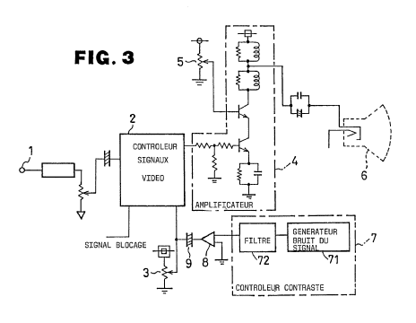
FR2691032 (brightness and contrast adjustment):
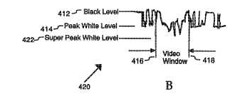
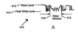
WO9905666 (generation of a higher luminance video window):
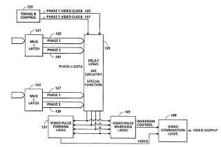
US5504462 (control of an intensity pulse signal in relation to pixel clock in a CRT or in a laser beam printer):
EP0840272 (feedback adjustment of the electron beam current):
US5786669 (FED emitters used just to produce the electron beam in a CRT; beam intensity controlled by the number of active microtips):
This place covers:
- Circuits for power management specific for CRTs;
- Details of power supply specific for CRTs.
Illustrative examples:
Special power supply for deflection amplifiers: US3863099.
Power control for user protection from EM radiation and excessive optical brightness: US5521652.
From X-rays: DE29900611U.
Power control for energy saving, to synchronize with computer standby / shutdown for an LCD, possibly applicabale also to a CRT: EP0863455.
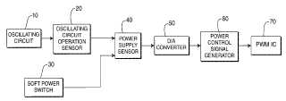
In combination with a soft power switch: US6092206.
Details of power control of cathode heater: US6084355.
This place does not cover:
Power supply in general |
Use the Indexing Codes G09G 2330/021 - G09G 2330/024 for power management.
This place covers:
Independent management of multiple screen areas in positions that are not quickly varied by an user interface (e. g. with a fixed tiling), e. g. with use of linked row pointers for controlling the screen partition and / or scrolling, e. g. using hardware mechanisms specific for CRTs.
Illustrative examples: to change the displayed information by activating different parts of the screen: EP0680776:

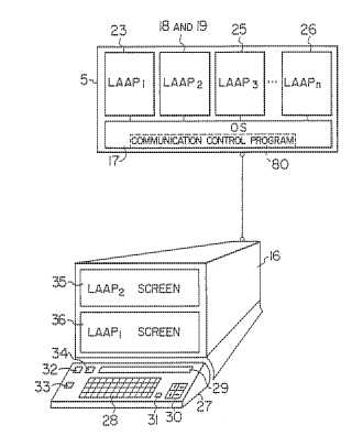
Systems for plural display areas on one screen tiling in x and y directions according to a descriptor data collection, but without user interface: EP0200036.
With hardware control of the video screen in different areas: US2006044216.
Same as above: US4550386.
Hardware control of a text area and of a screen area with a character menu: EP0274439.
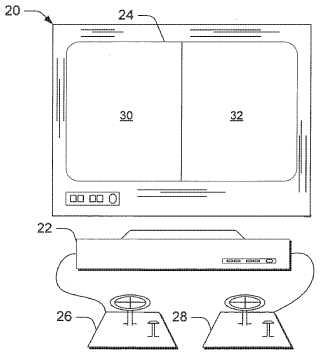
Systems with divided screen in two halves of the screen used by different users: EP0018759.
Attention is drawn to the following places, which may be of interest for search:
Multiple view displays | |
Display of multiple viewports (such as windows) | |
Split matrices (D.A: be careful. This is not really related.) | |
One image signal (VGA) contains plural images; a splitter divides and provides to plural displays | |
Split screen control with user interaction |
This place covers:
Display buffer/memory management; multiple monitors or variable display arrangements.
Illustrative examples: DE3607474
FR2559933
US4618858
Character generation system: EP0053661.
This place does not cover:
Using single beam tubes | |
With combined raster scan and calligraphic display | |
The beam directly tracing characters, the information to be displayed controlling the deflection | |
The deflection signals being produced by essentially digital means, e.g. incrementally | |
The deflection signals being produced by essentially analogue means | |
The beam tracing a pattern independent of the information to be displayed, this latter determining the parts of the pattern rendered respectively visible and invisible | |
Circuits for displaying horizontal and vertical lines | |
Flicker reduction circuits | |
The pattern of rectangular co-ordinates extending over the whole area of the screen, i.e. television type raster | |
For displaying digital inputs as analog magnitudes, e.g. curves, bar graphs, coordinate axes, singly or in combination with alpha-numeric characters | |
Details of a display terminal using a CRT, the details relating to the control arrangement of the display terminal and to the interfaces thereto | |
Details of the interface to the display terminal specific for a CRT | |
A small local pattern covering only a single character, and stepping to a position for the following character, e.g. in rectangular or polar co-ordinates, or in the form of a framed star | |
Using multi-beam tubes | |
Using tubes permitting selection of a complete character from a number of characters | |
Using tubes permitting selection of individual elements forming in combination a character | |
Using storage tubes | |
Using colour tubes |
Attention is drawn to the following places, which may be of interest for search:
Storage tubes (the storage effect being realized by means of the tube) |
This place covers:
Details of deflection circuits specific for computer generated displays (in absence of indications of features that render a deflection circuit so specific, not to be classified in G09G).
Illustrative examples:
Deflection circuits for distortion correction: US5070281.
GB1285554
DE19529448
Deflection in specially designed CRTs in a laser CRT with reduced beam diameter: US2002057384.
Sinusoidal deflection current for bidirectional scanning: GB2157136.
Attention is drawn to the following places, which may be of interest for search:
Arrangements of electrodes and associated parts for generating or controlling the ray or beam, e.g. electron-optical arrangement. | |
Arrangements for deflecting ray or beam; circuit arrangements for producing saw-tooth pulses or other deflecting voltages and currents. | |
Arrangements of electrodes and associated parts for generating or controlling the discharge, e.g. electron-optical arrangement, ion-optical arrangement. | |
Controlling tubes by external information, e.g. program control. | |
Generating pulses having essentially a finite slope or stepped portions | |
Manipulating pulses having a finite slope and not covered by one of the other main groups of this subclass. | |
Details of scanning of a TV system, by deflecting an electron beam in a CRT (includes documents for which the use in a TV or in a computer monitor is not specified) | |
Prevention of damage of the CRT in the event of failure of scanning |
This place covers:
Three-dimensional or perspective representation, rotation or translation of display pattern, hidden lines, shadows automatic brightness compensation half-tone display.
Illustrative examples:
Three-dimensional or perspective representation: EP0458692.
US4821210
US4841292
US3889107
Display that involves the spectator to use special glasses: DE4417664, US5162779.
GB2308284
This place does not cover:
Using storage tubes | |
Using colour tubes. Note: The usual kind of colour tubes with one beam per colour (usually RGB), each beam being individually controlled in intensity but all beams being commonly deflected, are considered as "single beam tubes" unless colour specifique details are disclosed |
Attention is drawn to the following places, which may be of interest for search:
Control of overall brightness | |
Aircraft flight instrument display | |
Oscilloscopes for three-dimensional representation | |
Vectorscopes | |
Image rendering, image processing | |
Stereoscopic TV-systems, details thereof |
This place covers:
CRTs combining a vector stroke display with a raster scan display, mostly superimposed.
Illustrative examples:
EP0158480
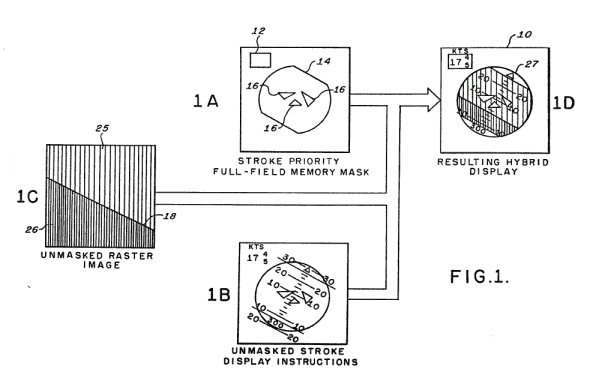
EP0043703
Attention is drawn to the following places, which may be of interest for search:
Raster displays with stroke-to-raster conversion are also placed in this class.
This place covers:
CRTs with vector stroke displays.
Illustrative examples:
Curve and line generators.
Curve generator: EP0288720.
Digital technique for constructing variable width lines: US4601002.
Enhancement of the resolution of end points of a line: US4939673.
Character generators specific for vector stroke displays, without reference to a specific digital or analog deflection technique.
Stroke writing character apparatus and method: EP0138339.
Video compensation apparatus.
Compensation of the delay between X and Y (deflection) channels and Z (intensity) channel in a stroke mode CRT display: US5047756.
Slew length timer for the determination of the time interval between start and end of a segment on the display: EP0108473.

Attention is drawn to the following places, which may be of interest for search:
Function generators (e.g. Circles and vectors for bit-mapped displays), eventually combined with smoothing | |
Writing vectors into a bit-mapped memory | |
General purpose image data processing |
This place covers:
For example:
Digital generation of character segments: FR2095711.
EP0130245
With introduction of a digital value to define stroke curvature: US3594756.
Line and curvature drawing.
Line generator based on Bresenham's algorithm: GB2207839.
Wide line drawing: EP0229693.
Curve stroke drawing: EP0014127.
This place covers:
For example:
Graphic data transcription apparatus using a writing plate: US3632874.
Use of a carrier drift arrangement to generate waveforms used for deflection in vector stroke displays: US3025342.
This place covers:
For example: GB2040146, FR2249597.
This place covers:
Illustrative example of subject matter classified in this place:

Attention is drawn to the following places, which may be of interest for search:
Flicker reduction other than flicker reduction circuits used for single beam cathode-ray tubes | |
Flicker reduction in television systems |
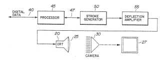
This place covers:
- interfacing with monochrome display monitors;
- video signals (e.g. camera signals ) combined with display data (e.g. computer display data);
- multisync monitor;
- CRT adapter for multiple CRT types;
- variable format in general;
- bidirectional scan;
- video mixer;
- scrambling of video signals;
- inversion control e.g. with a switch: black on white or white on black
- monochrome ==> monochrome with LUTs;
- coupling details display card <=> monitor.
Illustrative examples:
Screen saver: DE4142894.
Graphics display system: WO8906415.
Raster assembly processor: US4947257.
Interfacing video information and computer-generated graphics on a visual display terminal: US4958297.
Improving apparent smootheness on gray-scale displays: US4612540.
Displaying data in a second display area (obtained by overscan): US2002149593
Radiation elimination circuit: DE29917219U, DE29917219U.
Correcting the rotation of a video display. US2003189639.
This place does not cover:
Deflection circuits | |
Synchronisation between the display unit and other units, e.g. other display units, video-disc players | |
Control of the character-code memory, Resolution modifying circuits, e.g. variable screen formats, resolution change between memory contents and display screen | |
Control of display attribute | |
Control of the bit-mapped memory, Resolution modifying circuits, e.g. variable screen formats |
Attention is drawn to the following places, which may be of interest for search:
Prevention of data theft by detection of electromagnetic stray radiation of VDU | |
Coupling parts for selective co-operation with a counterpart in different ways to establish different circuits, e.g. For voltage selection, for series-parallel selection | |
Circuits special to multi-standard TV receivers | |
For additional information on a television signal |
This place covers:
Method and apparatus for enlarging a trend graph: US5261031.
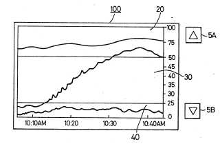
Waveform signal display controlling device and method: EP0987673.
Method to scale electrocardiograph (ECG) waveforms independent from display resolution: EP0932139.
Trace coloring system and method: US5959607.
Displaying graphic data: EP0636965.
Attention is drawn to the following places, which may be of interest for search:
Cathode-ray oscilloscopes for displaying analog inputs, singly or in combination with alpha-numeric characters | |
Television receiver circuitry for displaying supplementary, e.g. Alpha-numeric, information |
This place covers:
Arrangements for data processing done in order to adapt the incoming data to the display on a CRT; details of the deflection signals or driving signals of the CRT in dependance of the data to be displayed.
The codes G09G 1/165 and below apply only if a monitor-architecture can be identified (click to see definition; the same rule applies for G09G 3/2092 and G09G 5/003). The G09G 1/165 and below is used only in exceptional cases where the processing is clearly specific to a CRT. Anything that might as well be used for other technologies is to be classified under the G09G 5/003 and its (more detailed) sub-groups.
Illustrative examples:
Monitor calibration: US2003053001.
US2002057282
Screen alignment and positioning: US2002180769.
US2003001856
US4338597
US4081797
This place does not cover:
Details specific for a flat panel | |
Details suitable for both CRT and flat panel |
Attention is drawn to the following places, which may be of interest for search:
Interfacing with colour display | |
Control of matrices with row and column drivers | |
Using display panels | |
Using cathode-ray tubes |
In this place, the following terms or expressions are used with the meaning indicated:
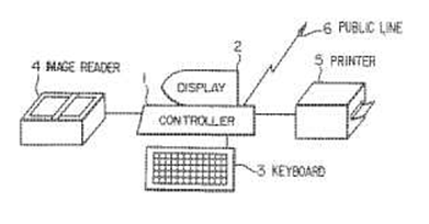
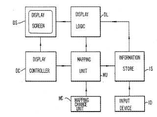
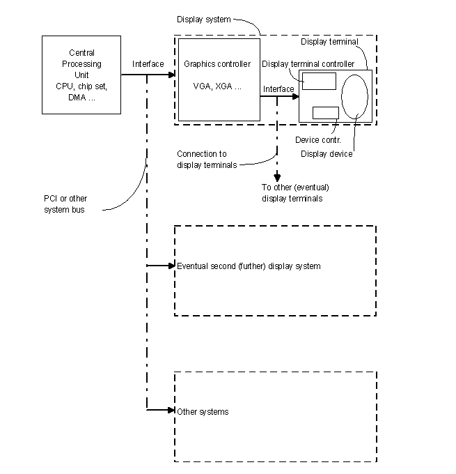
Display terminal | Means an apparatus connected to a source of display data (usually a graphics controller of a computer, or directlz to the computer itself) adapted to display images generated by this source of data. In general a "Display terminal" is an arrangement including a display device (e.g. a CRT with its driving electronic or a flat panel including its row and column drivers), a display device controller (the hardware and software (usually a microprocessor) that controls the display device and that allows its functioning by, for example, generating the signals that are needed to bring the data to the drivers) and a display terminal controller (the hardware and software used to control the display terminal as a whole and to interface the display terminal to the graphics controller, to adapt data and control signals, for example in an LCD driven by a VGA type graphics controller). |
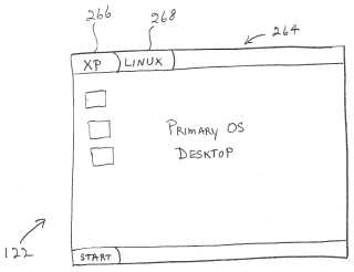
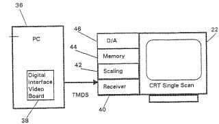
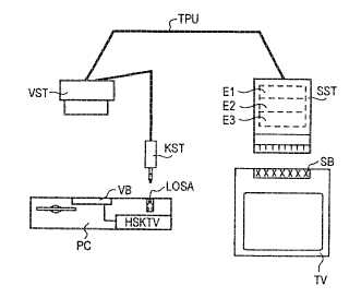
This place covers:
Illustrative examples: Parallel data display of multiple executing environments:US2004226041.
Single horizontal scan range CRT monitor: WO0129811.
Improved signal restoration: US6529248.
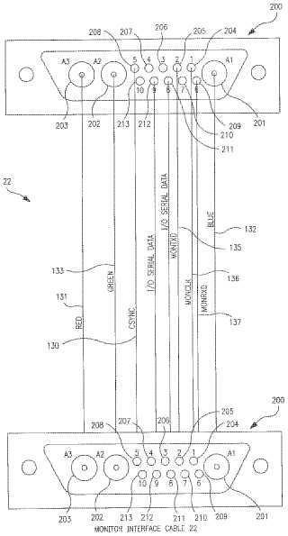
Display monitor control and communications bus interface: US6590572.
TV-PC conversion cable. DE19630941.
Adding display data channel to existing display: GB2294135.
Separate message section on CRT display device: US5384576.
This place does not cover:
Specific for a flat panel | |
Suitable for both CRT and flat panel | |
Control arrangements or circuits for visual indicators common to cathode-ray tube indicators and other visual indicators, Details of the interface to a display terminal |
Attention is drawn to the following places, which may be of interest for search:
Interfacing with colour display | |
Control of matrices with row and column drivers | |
Using display panels | |
Using cathode-ray tubes |
The class G09G 1/167 includes "details of the interface to a CRT display terminal". If a television set is used as a display terminal, the class G09G 5/006 should be given and not the G09G 1/167 . This is because the signals generated for a television set are standard television signals (NTSC or PAL...): the television itself might have an lcd or plasma panel. If the interface to the display terminal has some details about the signals of the interface, and if these details are clearly means for a CRT terminal (e.g. level or polarity of a h-synch or v-synch signals, black level adjustment...) then the documents are classified in the G09G 1/167 .
This place covers:
Illustrative example of subject matter classified in this group (US3777059):
This place covers:
Multiple beams and beam deflection necessary! A flat panel using deflection is considered as being a multiple beam CRT.
Illustrative examples:
Common focus: US5382883.
US4063233
Separated regions: EP1054379, DE1137143.
For intensity control: US5691608,
FR2296228.
Attention is drawn to the following places, which may be of interest for search:
Using large area or array source | |
Producing multiple scanning | |
With more than one beam in a tube |
This place covers:
Illustrative example of subject matter classified in this group (GB929976):
and US2925526, US2866189.
Attention is drawn to the following places, which may be of interest for search:
Tubes therefor |
This place covers:
Illustrative examples of subject matter classified in this group:
US3639910
US4107741
US3902012
Attention is drawn to the following places, which may be of interest for search:
Tubes therefor |
This place covers:
Specific circuits for CRT tubes (e.g. for a penetron tube).
Illustrative examples:
Color shadow mask cathode ray tube: WO8203494.
Position programmed colour CRT: NL7505346.
Colour image display system - CRT with display areas and associated circuitry: DE2329081.
Multi-color crt display system: US3280254.
Cathode ray tube with addressable nanotubes: US6515639.
Image processing system utilizing brush profile: US5412767.
Attention is drawn to the following places, which may be of interest for search:
Display of colours in general | |
Measurement of color | |
Tubes therefor | |
Color picture communication systems |
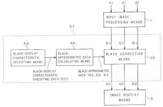
This place covers:
- specific interface circuits between the color processing output circuit (e.g. output of video ram or color lookup table if present) and the color display tube;
- fiber-optic data link between color control circuit and CRT-monitor;
- color normalisation for display terminals: e.g. adapting the LUT content to the specific colors of the phosphors and to the gamma curve of the display;
- monitor sensing circuits (color <=> monochrome).
Illustrative examples:
Display device with black correction unit: US2002150293.
Compensation method for improving color saturation and image quality of plasma display panel by adjusting the strength of input image signals: US2002167467.
Plasma displays
Method and apparatus for automatically calibrating a CRT: EP0539943.
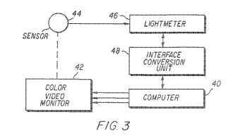
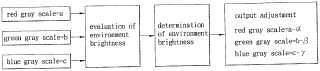
Image display system that performs grayscale correction in accordance with the on-site environment: US2003147053.
Light output correction of a display monitor. EP0514025.
Multi-spectral color correction. US2002122044.
This place covers:
- Control of flat panel display in general.
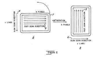
- Control of rotatable displays: to display information on a screen in either a horizontal orientation (landscape) or vertical orientation (portrait) the display controller is able to change the orientation of the displayed information. In some cases the physical screen is also rotated.
Attention is drawn to the following places, which may be of interest for search:
Control of illumination source, e.g. backlight for non-intrinsically emissive displays | |
Scanning systems for optical devices or arrangements using movable or deformable optical elements for controlling the intensity, colour, phase, polarisation or direction of light, e.g. switching, gating, modulating. | |
Visual indicators for traffic control systems. |
This place covers:
- Using an intermediate record carrier such as a film slide.
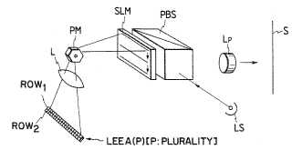
- Control of projection systems or displays.
- Display of non-alphanumerical information, solely or in combination with alphanumerical information, e.g. digital display on projected diapositive as background.
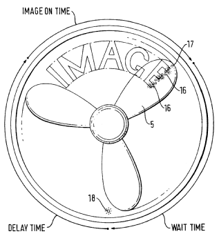
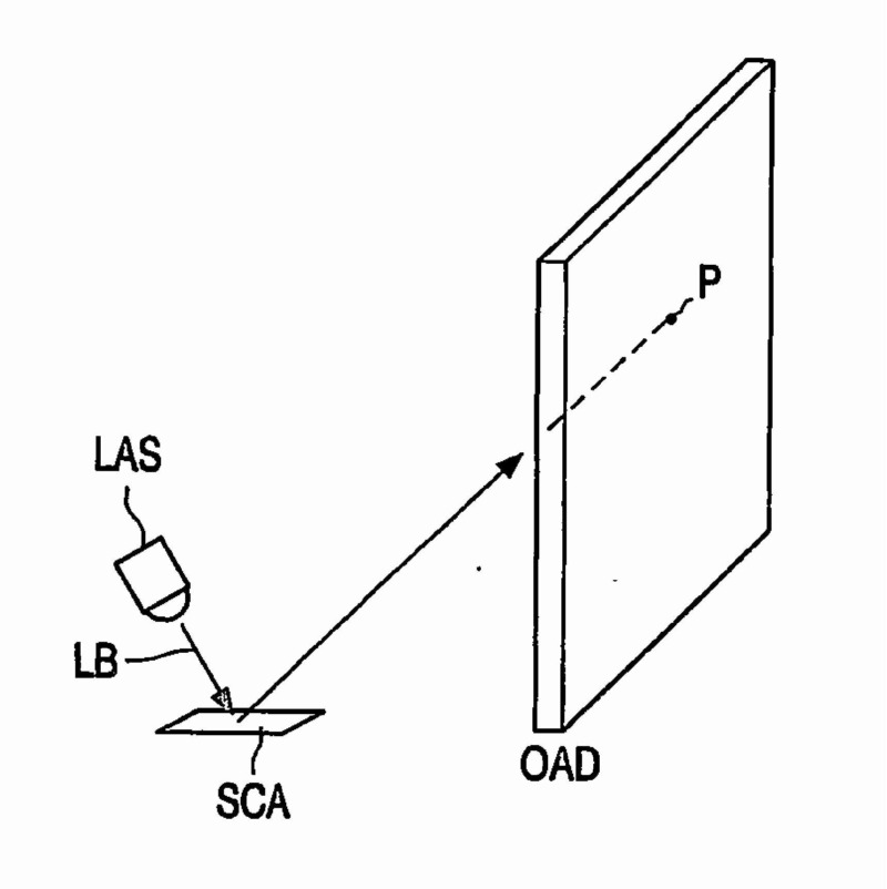
- Control of rotating or moving display (Roled): one or more (usually linear) arrays of light emitting elements are rotated or moved to display an image on a virtual screen created on the surface of revolution or movement.
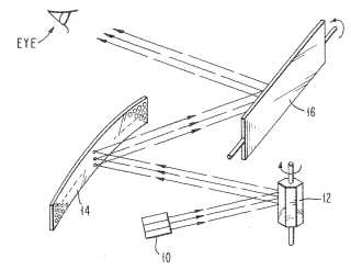
- Control of stereoscopic computer displays.
- Control of multiple view displays, i.e. displays producing e.g. two images which are visible under different viewing angles.
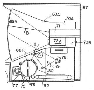
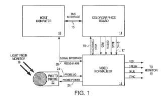
Illustrative examples of subject matter classified in this place:
1.
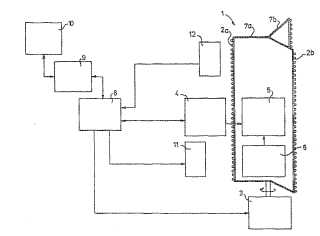
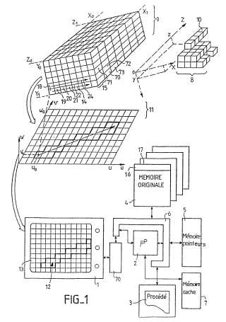
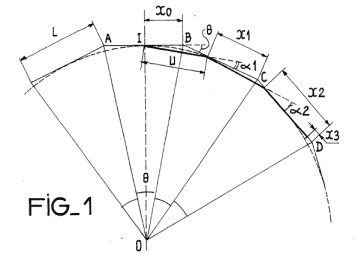
Figure 1 illustrates a display device with rotating display elements.
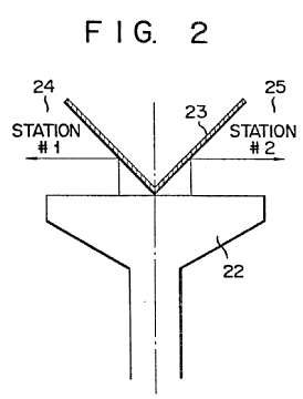
2.

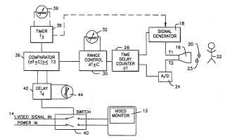
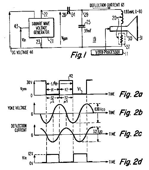
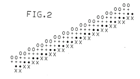
Figure 2 illustrates a high-speed link for rotating display.
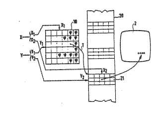
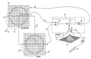
3.
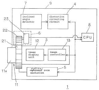
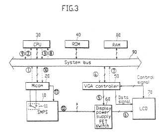
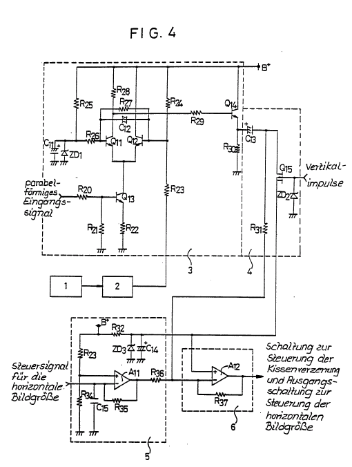
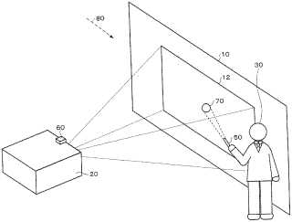
Figure 3 illustrates a projector with image modified to compensate distortions from projecting onto a screen from a side, so called "Keystone correction".
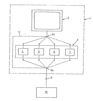
4.

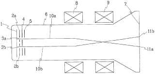
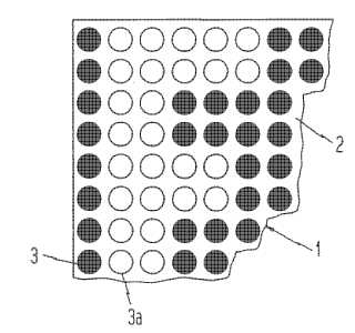
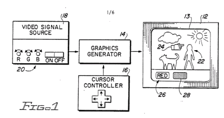
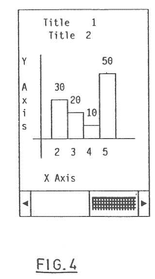
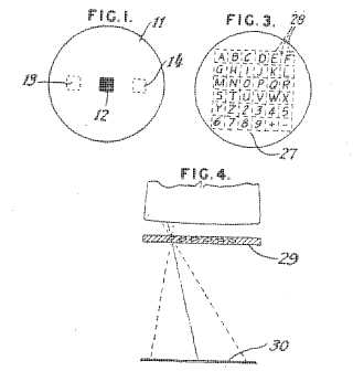
Figure 4 illustrates a coloured display which displays two different images depending on the viewing direction.
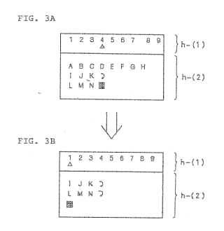
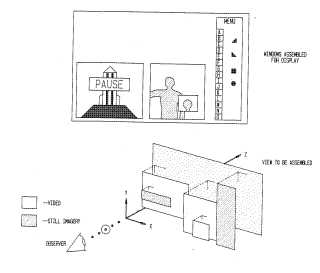
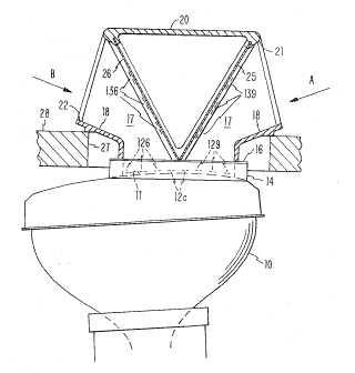
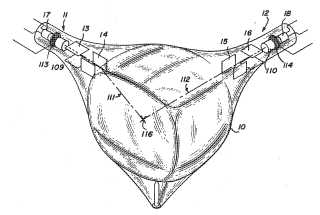
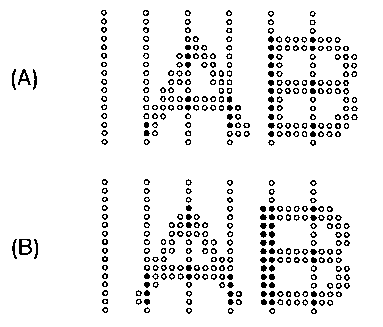
5a.
5b.

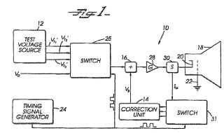
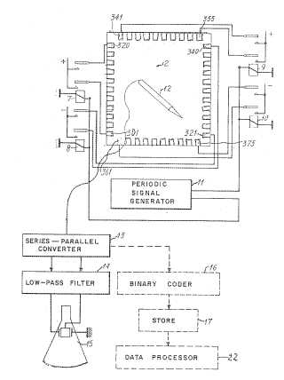
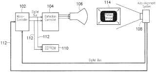
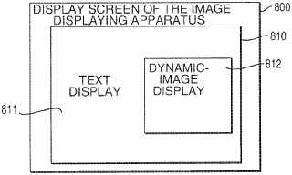
Figures 5a and 5b illustrate an image display apparatus.
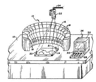
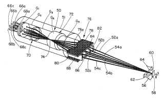
6.
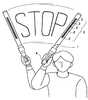
Figure 6 illustrates a baton using light emitting cell array to form a display.
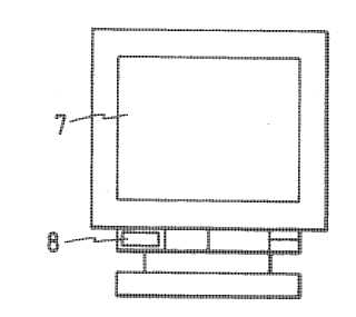
7.
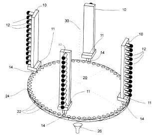
Figure 7 illustrates a rotating drum or blade with linear array of light sources.
This place does not cover:
Slide projectors |
Attention is drawn to the following places, which may be of interest for search:
Circuits for displaying split screens (including CRTs with divided screens) | |
Projection display for cars (e.g. HUDs) | |
Light guides specially adapted for lighting devices or systems | |
Mountings, adjusting means, or light-tight connections, for optical elements adapted for automatic focusing or varying magnification | |
Systems for automatic generation of focusing signals including a sight line detecting device | |
Head mounted displays | |
Head mounted displays characterised by optical features | |
Head mounted displays characterised by mechanical features | |
Other optical systems for producing stereoscopic or other 3D effects | |
Stereoscopic and volumetric TV display | |
Other optical systems for producing stereoscopic or other 3D effects, the image being built up from image elements distributed over a 3D volume | |
Other optical systems for producing stereoscopic or other 3D effects, the volume being constructed from a stack or sequence of 2D planes | |
Slide projectors per se | |
Displaying, advertising, signs, labels or name-plates, seals | |
Mobile visual advertising | |
Scanning details of television systems by switched stationary formation of lamps, photocells or light relays (e.g. optical fibers) | |
Projectors for colour picture display | |
Stereoscopic video systems |
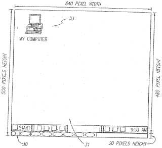
This place covers:
Display devices wherein, different from a standard panel:
- the displayed image has a higher resolution than the display device itself; and
- at any time, only part of the complete image is displayed.
Illustrative example: EP0709818
This place covers:
Testing or inspecting flat panel displays by electrical means, i.e. by checking electrical signals and parameters while driving the panel, possibly under special driving conditions specific for the test.
This place does not cover:
Testing of individual LEDs | |
Testing lamps | |
Testing of optical features of LCD displays |
Attention is drawn to the following places, which may be of interest for search:
Investigating or analysing materials by the use of optical means, i.e. using infrared, visible, or ultraviolet light; etc. Inspecting patterns on the surface of objects. | |
Testing of electronic circuits | |
Diagnosis, testing or measuring for television systems or their details |
Does not apply to testing during manufacturing of non-finished flat panel displays, when the result of the testing are used to determine parameters of the subsequent manufacturing steps (such testing is regarded as a step of manufacturing).
Also, does not apply if the testing/inspecting is carried out by optical means (e.g. optical measurements), which is classified in G01R. In some "mixed" or doubtful cases classifications in both G09G 3/006 and G01R may be given.
Does not apply to mere calibration of display devices, i.e. to the setting of control parameters for properly functioning displays based on detection of operation parameters (e.g. detection of colour, luminance etc), for which Indexing Code G09G 2320/0693 applies.
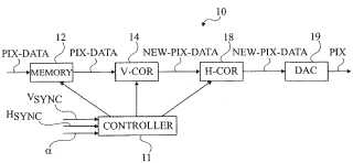
This place covers:
- Control of displays using a deflected and modulated light beam for directly producing the displayed image on the screen.
- Control of displays using deflected and modulated light beams, which are generated by a linear array, for directly producing the displayed image on the screen.
- Control of displays using a deflected and modulated light beam to control an array of photosensitive elements that receive it and consequently command each a pixel display element.
- Control of displays using a deflected and modulated light beam for optically writing image data on a photosensitive surface that commands a display such as a light modulator.
- Control of stereoscopic displays.
- Control of multiple view displays, i.e. displays producing e.g. two images which are visible under different viewing angles.
Illustrative examples:
US3739370 (deflected light beam producing the displayed image on the screen)
US4097115 (Control of optical scanning device for producing a multiple line scan using a linear array of sources and a textured scanned surface)
US2006132452 (control of a display using a deflected and modulated light beam to control an array of photosensitive elements that receive it and consequently command each a pixel display element)
US5463468 (control of a display usinga deflected and modulated light beam for optically writing image data on a photosensitive surface that commands a display such as a light modulator)
This place covers:
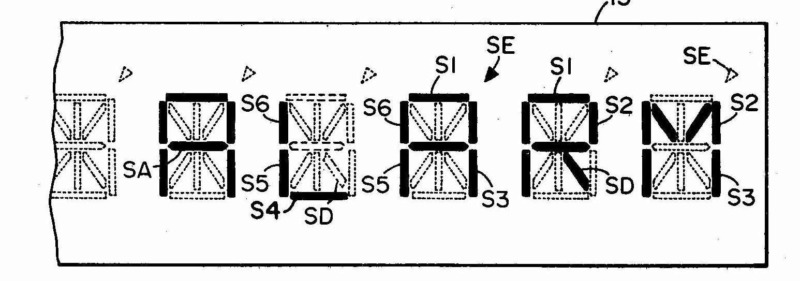
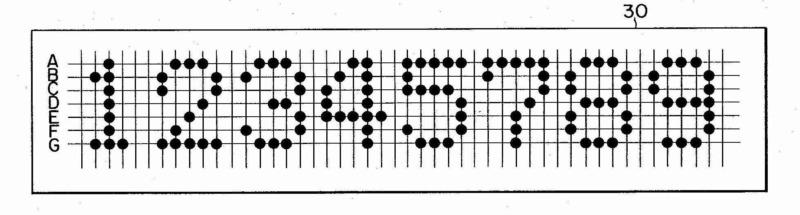
- Control of displays for displaying a character composed by a fixed number of display elements as segments or dots, i.e. the character position within the display device is fixed, and the specific character composition by combination of individual display elements to be displayed is selected from a plurality of predefined character compositions without specifying a display technology or with details of two or more display technology, but aspects of general character for various, if not all display technologies.
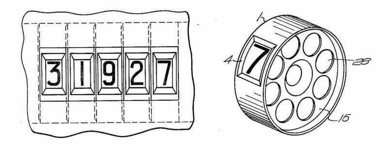
- Control of displays for displaying a character by selection from a plurality of complete characters.
Attention is drawn to the following places, which may be of interest for search:
Control of displays having display elements arranged in a matrix |
Examples
US4458243 (control of a segment display with each character being loaded from a ROM and generated at a fixed position by 14 segments)
US4504829 (control of a dot character display with each character being loaded from a memory and generated at a fixed position by 5 times 7 dots)
This place covers:
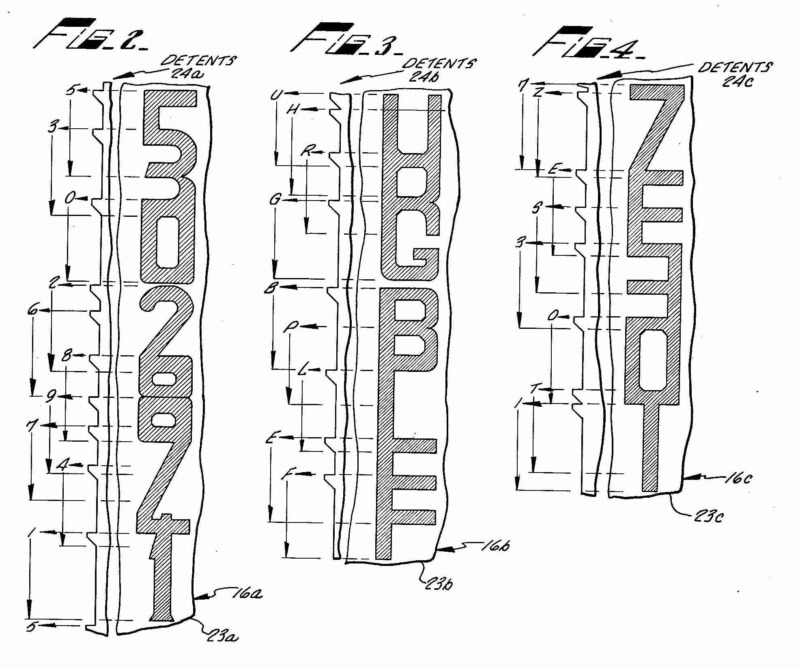
Control of displays for displaying a character by selection from a plurality of complete characters.
Illustrative examples: US3218625 (control of a display wheel for converting binary code to display position)
US3200396 (control of a display using fused characters
This place covers:
Control of displays using controlled light sources for displaying a character composed by a fixed number of display elements as segments or dots.
Attention is drawn to the following places, which may be of interest for search:
Control of displays using controlled light sources as display elements arranged in a matrix |
This place covers:
Control of displays using incandescent filaments, i.e. incandescent light bulbs, for displaying a character composed by a fixed number of display elements as segments or dots.
Attention is drawn to the following places, which may be of interest for search:
Control of displays using incandescent filaments, i.e. incandescent light bulbs, as display elements arranged in a matrix |
This place covers:
Control of displays using gas tubes, e.g. luminous plasma discharge cells, for displaying a character composed by a fixed number of display elements as segments or dots.
Attention is drawn to the following places, which may be of interest for search:
Control of displays using luminous gas-discharge cells, e.g. luminous plasma discharge cells, as display elements arranged in a matrix |
This place covers:
Control of displays using electroluminescent display elements for displaying a character composed by a fixed number of display elements as segments or dots.
This place covers:
Control of displays using electroluminescent display elements, which are semiconductor devices, e.g. diodes or transistors, for displaying a character composed by a fixed number of display elements as segments or dots.
Attention is drawn to the following places, which may be of interest for search:
Control of displays using electroluminescent display elements, which are semiconductor devices, e.g. diodes or transistors, arranged in a matrix | |
Control of displays using organic electroluminescent display elements, which are semiconductor devices, e.g. diodes or transistors, arranged in a matrix |
This place covers:
- Control of displays using display elements, which do not emit light, but selectively control the light from an independent light source by transmission, reflection, or absorption of, for displaying a character composed by a fixed number of display elements as segments or dots
- Control of an independent light source used in displays using display elements, which selectively control the light from the independent source, for displaying a character composed by a fixed number of display elements as segments or dots
Attention is drawn to the following places, which may be of interest for search:
Control of displays using display elements arranged in a matrix, which do not emit light, but selectively control the transmission, reflection, or absorption of light from an independent light source | |
Control of an independent light source used in displays using display elements arranged in a matrix, which selectively control the light from the independent source |
This place covers:
Control of displays using liquid crystal display elements for displaying a character composed by a fixed number of display elements as segments or dots.
Attention is drawn to the following places, which may be of interest for search:
Control of displays using liquid crystal display elements arranged in a matrix |
This place covers:
Control of displays using electrochromic display elements for displaying a character composed by a fixed number of display elements as segments or dots.
Attention is drawn to the following places, which may be of interest for search:
Control of displays using electrochromic display elements arranged in a matrix |
This place covers:
- Control of displays having display elements arranged in a matrix with details of two or more display technology, but aspects of general character for various, if not all display technologies.
- Control of displays having display elements arranged in a matrix without specifying a display technology.
Attention is drawn to the following places, which may be of interest for search:
Electronic inspection or testing of displays and display drivers | |
Control arrangements or circuits for presentation of a single character by selection from a plurality of characters, or by composing the character by combination of individual elements, e.g. segments |
For control arrangements or circuits with details concerning the control of intermediate tones of elements arranged in a matrix, a code within G09G 3/2007 is to be given, and with details concerning the colour, G09G 3/2003 is to be given. For control arrangements or circuits for elements arranged in a matrix with details of one specific display technology, a code corresponding to the specific display technology is to be given, e.g. G09G 3/38 for using electrochromic elements.
This place covers:
Control of a display to display a coloured image with aspects specific for flat panel displays.
This place does not cover:
Control of a liquid crystal display for displaying a coloured image |
Attention is drawn to the following places, which may be of interest for search:
Control of a display for displaying a coloured image in general |
This place covers:
Control of a display to display an image having intermediate tones with aspects specific for flat panel displays.
Does not apply to a control of the brightness of a display as a whole, for which the Indexing Code G09G 2320/0626 should be given.
This place covers:
Control of a display to display an image having intermediate tones by modulating the amplitude of the analog signals applied to the display elements.
This code is only given if specific details of the amplitude modulation are present or the amplitude modulation plays a significant role, but not for indicating the presence of a usual amplitude modulation in a document.
This place covers:
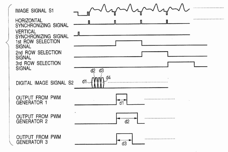
Control of a display to display an image having intermediate tones by modulating the duration of a single pulse applied to the display element or by modulating the duration of several pulses applied to the display element in the same manner.
Illustrative examples:
US2003/0117420 (modulation of the intermediate tone displayed by a pixel by varying the width applied to a data electrode during a scan period determined by the scan signal applied to the scan electrode)
This place covers:
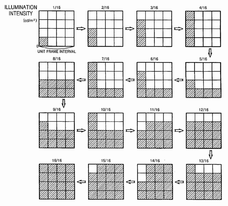
- Control of a display to display an image having intermediate tones by frame rate control or temporal dithering, i.e. the intermediate tone is generated by selectively activating a display element in a number of frames.
- Control of a display to display an image having intermediate tones by modulating the duration of several pulses applied to the display element in a different manner for each pulse.
This place covers:
- Control of a display to display an image having intermediate tones by using sub-frames, i.e. selectively activating a display element in a number of non-overlapping time periods, in which a frame is subdivided.
- Control of a display to display an image having intermediate tones by using sub-frames, i.e. selectively activating a display element in a number of non-overlapping time periods, in which a frame is subdivided, wherein no details of the ratios of the duration of one sub-frame to the duration of another sub-frame are given.
- Control of a display to display an image having intermediate tones by using sub-frames, i.e. selectively activating a display element in a number of non-overlapping time periods, in which a frame is subdivided, wherein the durations of the sub-frames are binary numbers, i.e. the duration of the second shortest sub-frame is twice the duration of the shortest sub-frame, the third shortest sub-frame is four times the duration of the shortest sub-frame, ...,and the duration of the nth shortest sub-frame is (n-1) times the duration of the shortest sub-frame.
For plasma display panels, this code is only to be given if specific details of the generation of intermediate tones using sub-frames are present or the generation of intermediate tones using sub-frames plays a significant role, but not for indicating the presence of a usual generation of intermediate tones using sub-frames in a document.
This place covers:
Control of a display to display an image having intermediate tones by using sub-frames having all the same duration, i.e. a frame rate control with the intermediate tone being generated by selectively activating a display element in a number of sub-frames.
This place covers:
Control of a display for displaying an image having intermediate tones by using sub-frames, wherein the durations of the sub-frames are not all binary numbers, i.e. at least for one sub-frame it does not hold that the duration of the nth shortest sub-frame is (n-1) times the duration of the shortest sub-frame.
This code is not given if for all the sub-frames the ratio of the duration of one sub-frame to the duration of another sub-frame is a binary number, but one or more of the sub-frames are split in two or more time periods, wherein the time periods are still addressed by the same binary bit.
Illustrative examples:
GB2327798 (ratio of the durations of the display period of the fourth shortest sub-frame and the shortest sub-frame is seven, not eight)
This place covers:
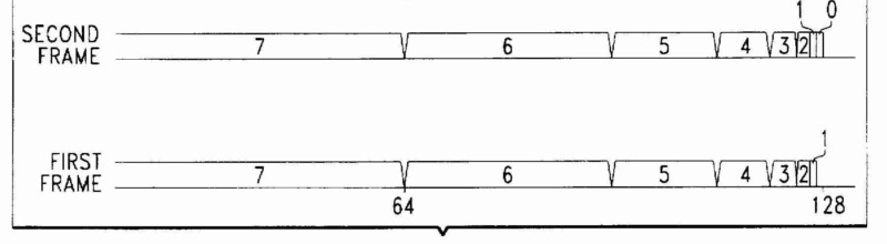
Control of a display for displaying an image having intermediate tones by using sub-frames, wherein one or more sub-frames corresponding to the most significant bits are split into two or more time periods, which are still addressed by the same bit.
This code is not given if the sub-frame corresponding to the most significant bit is not split, but only other sub-frames corresponding to lower bits are split. This code is also not given if the time periods, into which the sub-frames corresponding to the most significant bits are split, are individually addressed by separate bits, but the code G09G 3/2029 might apply.
Illustrative examples:
EP0774745 (sub-frame with the longest duration and corresponding to the most significant bit is split in two periods controlled by the same most significant bit)
This place covers:
Control of a display for displaying an image having intermediate tones by using sub-frames, wherein one or more sub-frames corresponding to the least significant bits are specifically controlled to increase the number of intermediate tones without applying to narrow pulses.
This code is not given if the sub-frame corresponding to the least significant bit is not specifically controlled, but only other sub-frames corresponding to higher bits.
Illustrative examples:
US5751379 (sub-frame with the shortest duration and corresponding to the least significant bit is displayed only every second frame)
This place covers:
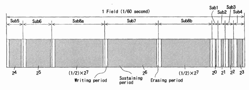
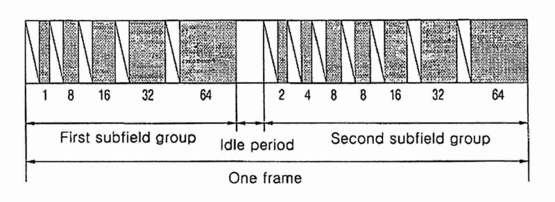
Control of a display for displaying an image having intermediate tones by using sub-frames, wherein the sub-frames are organized in consecutive sub-frame groups, e.g. the groups being separated by a pause period, or the sub-frames within one group having a common addressing scheme, or a specific order with respect to the size of the corresponding bits.
Illustrative examples:
EP1710777 (sub-frames of one frame are arranged in two groups divided by an idle period and with increasing durations within each group)
This place covers:
Control of a display for displaying an image having intermediate tones by using dithering, i.e. by adding a noise signal to the image signal or the gradation threshold.
This place does not cover:
Control of a display to display an image having intermediate tones by frame rate control or temporal dithering, i.e. the intermediate tone is generated by selectively activating a display element in a number of frames | |
Control of a display for displaying an image having intermediate tones by using error diffusion, i.e. distributing the quantization error to neighbouring display elements |
This place covers:
Control of a display for displaying an image having intermediate tones by using dithering, wherein the noise signal added to the image signal or the gradation threshold is random noise.
This place covers:
Control of a display for displaying an image having intermediate tones by using dithering, wherein the noise signal added to the image signal or the gradation threshold is a spatial dither pattern applied to the display element and its neighbouring display elements.
This place covers:
Control of a display for displaying an image having intermediate tones by using dithering, wherein the noise signal added to the image signal or the gradation threshold is a spatial dither pattern applied to the display element and its neighbouring display elements, and the spatial dither pattern is varied in time, e.g. from one frame to the next frame, and cyclically, i.e. the same pattern is reused after a certain time period.
This place covers:
Control of a display for displaying an image having intermediate tones by using error diffusion in space, i.e. distributing the quantization error to neighbouring display elements.
Illustrative examples:
EP1587053 (error diffusion in space; sections 0027, 0028).
This place covers:
Control of a display for displaying an image having intermediate tones by using error diffusion in time, i.e. distributing the quantization error to the next frame.
Illustrative examples:
EP1583063 (error diffusion in time; section 0143).
This place covers:
Control of a display for displaying an image having intermediate tones by using error diffusion in space and time, i.e. distributing the quantization error to the neighbouring display elements and the next frame.
Illustrative examples:
US2009/0128693 (quantization error is distributed within the same frame to neighbouring display elements and to the same display element in the next frame)
This place covers:
Control of a display to display an image having intermediate tones by varying the area of a display element, which is in one display state, relative to the remaining area of the display element, which is in another display state.
This place does not cover:
Control of a display using liquid crystals having memory effect to display an image having intermediate tones by varying the area of the display element, which is in one display state, relative to the remaining area of the display element, which is in another display state |
Attention is drawn to the following places, which may be of interest for search:
Portions of a pixel that are physically separated or separately controlled are not a case of generating intermediate tones by domain-size control but by using sub-pixels |
Illustrative examples:
US2005174623 (modulation of the intermediate tone displayed by an electrochromic display element by varying its coloration area)
This place covers:
Control of a display to display an image having intermediate tones by display elements (pixel) having two or more physically separated or separately controllable portions (sub-pixels).
This place does not cover:
Control of a display using liquid crystals having memory effect to display an image having intermediate tones by display elements (pixels) having two or more separately controllable or physically separated portions (sub-pixels) |
Attention is drawn to the following places, which may be of interest for search:
Portions of a pixel that are not physically separated and not separately controlled, but exploit instead a stepped variation across the pixel of a physical variable that affects the state of the pixel itself, are not a case of sub-pixels but of domain size control |
Illustrative examples:
US2002/0195969 (modulation of the intermediate tone by providing two separately selectable organic electroluminescent display element with different areas for each image pixel)
This place covers:
Control of a display to display an image having intermediate tones by using two or more methods of generating the intermediate tones together, e.g. by using both sub-pixels and error diffusion.
Additional codes within G09G 3/2007 should also be given, to indicate which methods of generating the intermediate tones are combined. Code G09G 3/2011 is only given if specific details of the amplitude modulation are present.
As using sub-fields for the control of a plasma display panel to display an image having intermediate tones is a standard method, this code is not given for the combination of using sub-fields with a single other method of generating the intermediate tones in a plasma display panel.
Illustrative examples:
US2009/0128473 (combination of amplitude modulation with using sub-pixels for generating intermediate tones in an LCD)
This place covers:
Control of a display to display an image having intermediate tones by using amplitude modulation and time modulation.
This place does not cover:
Control of a display for displaying an image having intermediate tones by using error diffusion in space and time |
Additional codes of G09G 3/2014 or within G09G 3/2018 should also be given to indicate which time modulation method of generating the intermediate tones is used, while the code G09G 3/2011 is only given if specific details of the amplitude modulation are present.
Illustrative examples:
US2009/0051708 (combination of amplitude modulation with pulse width modulation for generating intermediate tones in an OLED display)
This place covers:
Details of the control of a display terminal in a monitor-architecture using a flat panel display, e.g. arrangements for processing of the image data as an adaption for display on the flat panel, or setting of parameters for a flat panel display.
This place does not cover:
Details of the control of a display terminal in a monitor-architecture using a CRT | |
Details of the control of a display terminal in a monitor-architecture in general suitable for both CRT and flat panel |
Attention is drawn to the following places, which may be of interest for search:
Control of a display for displaying a coloured image in general |
Illustrative example of subject matter classified in this group:
In this place, the following terms or expressions are used with the meaning indicated:
Display terminal | Means an apparatus connected to a source of display data (usually a graphics controller of a computer, or directly to the computer itself) adapted to display images generated by this source of data. In general a "Display terminal" is an arrangement including a display device (e.g. a CRT with its driving electronic or a flat panel including its row and column drivers), a display device controller (the hardware and software (usually a microprocessor) that controls the display device and that allows its functioning by, for example, generating the signals that are needed to bring the data to the drivers) and a display terminal controller (the hardware and software used to control the display terminal as a whole and to interface the display terminal to the graphics controller, to adapt data and control signals, for example in an LCD driven by a VGA type graphics controller). |
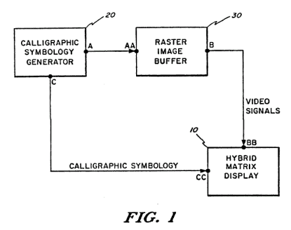
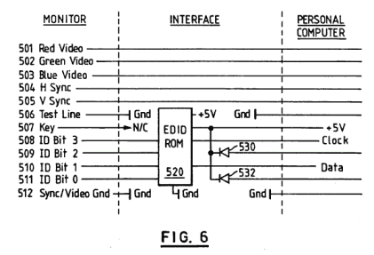
Monitor-architecture | means a source of pixelwise image data (rendered data, e.g. RGB data in a VGA video controller; see "Graphics controller" in below figure), e.g. obtained by transforming high-level image descriptions (e.g. graphics primitives) into pixel-wise image data, or by handling analogue video data, or by decompressing compressed video data, an image display unit, which receives said pixel-wise image data (see "Display terminal" in below figure), and an interface between said source of pixelwise image data and said image display unit (commonly RGB-cable with sync-signals, but also other interfaces like USB-bus). A monitor-architecture cannot be identified, if it is not clear where the processing described is located (that is also outside said image display unit); or if the structure of the display system has to be modified if the technology of the display changes ( e.g. in a mobile telephone, in which the drivers are normally controlled by the main CPU). |
This place covers:
Details of an interface to a display terminal in a monitor-architecture using a flat panel display, e.g. arrangements for processing of the image data as an adaption for display on the flat panel, or setting of parameters for a flat panel display.
This place does not cover:
Details of an interface to a display terminal suitable for both CRT and flat panel in a monitor-architecture in general |
This place covers:
Control of displays using controlled light sources as display elements arranged in a matrix.
Attention is drawn to the following places, which may be of interest for search:
Control of displays using controlled light sources for displaying a character composed by a fixed number of display elements as segments or dots |
Examples:
US5920154 (control of a field emission matrix display)
This place covers:
Control of displays using incandescent filaments, i.e. incandescent light bulbs, as display elements arranged in a matrix.
Attention is drawn to the following places, which may be of interest for search:
Control of displays using incandescent filaments, i.e. incandescent light bulbs, for displaying a character composed by a fixed number of display elements as segments or dots |
Illustrative example: US5920154 (control of an incandescent lamp matrix display)
This place covers:
Control of displays using incandescent filaments, i.e. incandescent light bulbs, as display elements arranged in a matrix, which are controlled to give the appearance of a moving sign.
Attention is drawn to the following places, which may be of interest for search:
Control of flat panel displays to give the appearance of moving signs in general |
This place covers:
Control of displays using luminous gas-discharge cells, e.g. luminous plasma discharge cells, as display elements arranged in a matrix.
Attention is drawn to the following places, which may be of interest for search:
Control of displays using gas tubes for displaying a character composed by a fixed number of display elements as segments or dots |
This place covers:
Control of displays using luminous gas-discharge cells having intermediate tones with aspects specific for displays using luminous gas-discharge cells.
This place does not cover:
Using alternating current (AC) panels |
Attention is drawn to the following places, which may be of interest for search:
Control of a display to display an image having intermediate tones with aspects specific for flat panel displays in general |
For a control of the brightness of a display as a whole, the Indexing Code G09G 2320/0626 should be given in addition.
Illustrative examples:
US5835072 (different intermediate tones are generated in a plasma display panel by varying the value of the voltage applied to the address electrodes during the addressing phase, and a subsequent sustain phase with the application of sustain pulses having different values)
This place covers:
Control of displays using luminous gas-discharge cells as display elements arranged in a matrix, wherein the discharge is caused by the application of signals to the gas-discharge cell having a particular high frequency, i.e. significantly higher than known from other displays using luminous gas-discharge cells as display elements arranged in a matrix.
Illustrative examples:
US2004/0056827 (application of pulses with a frequency of 1MHz to the address electrodes during the sustaining phase)
This place covers:
Control of displays using luminous gas-discharge cells as display elements arranged in a matrix, wherein in a discharge cell, some of the electrodes that play a role during the discharge are in contact with the ionized gas (as in DC type panels), some are not (as in AC type panels).
Illustrative examples:
US2004/0207572 (control of a plasma display panel with scan, sustain, and address electrodes not in contact with the ionized gas, and further electrodes in contact with the ionized gas)
This place covers:
Control of displays using luminous gas-discharge cells as display elements arranged in a matrix, wherein in a discharge cell, the electrodes that play a role during the discharge are in contact with the ionized gas.
Illustrative examples:
US5332949 (control of a plasma display panel with scan, sustain, and address electrodes in contact with the ionized gas)
This place covers:
Control of displays using luminous gas-discharge cells as display elements arranged in a matrix in a DC panel, wherein the discharge is sequential transferred from an input position to a further display position.
This place covers:
Control of displays using luminous gas-discharge cells as display elements arranged in a matrix in an AC panel, wherein in a discharge cell the electrodes that play a role during the discharge are not in contact with the ionized gas.
Only to be given in exceptional cases, when none of the subgroups of G09G 3/288 applies.
This place covers:
Control of displays using luminous gas-discharge cells as display elements arranged in a matrix, wherein the discharge is sequential transferred from an input position to a further display position.
Attention is drawn to the following places, which may be of interest for search:
Display panels with cold-cathode tubes |
Examples:
US5212472 (discharge is sequentially transferred, as discharge in the previous cell generates charges to enable a discharge in the adjacent next cells)
This place covers:
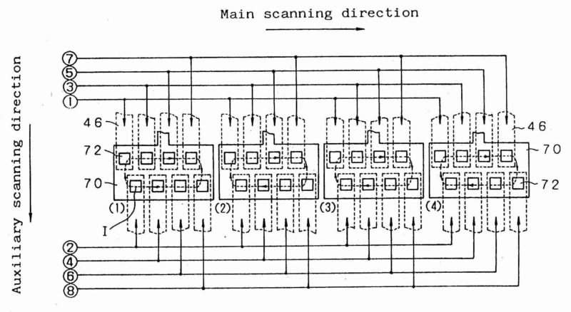
Control of displays using luminous gas-discharge cells as display elements arranged in a matrix in an AC panel with details of the control of the gas-discharge cell or the shape of the pulses applied to the electrodes of the gas-discharge cell.
This place covers:
Control of displays using luminous gas-discharge cells as display elements arranged in a matrix in an AC panel with details of the control of the gas-discharge cell or the shape of the pulses applied to the electrodes of the gas-discharge cell for generating an erase discharge outside the addressing phase, a reset discharge, or a priming discharge.
This place covers:
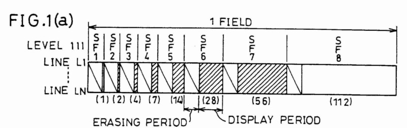
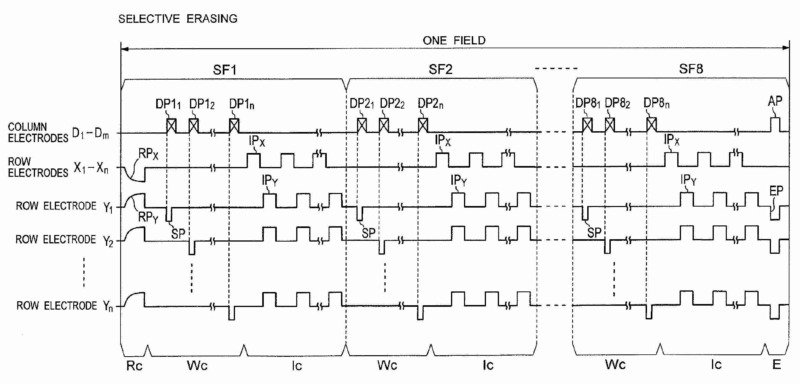
Control of displays using luminous gas-discharge cells as display elements arranged in a matrix in an AC panel with details of the control of the gas-discharge cell or the shape of the pulses applied to the electrodes of the gas-discharge cell for generating an erase discharge outside the addressing phase and outside the reset phase at least once per frame.
Illustrative example of subject matter classified in this place:
The Figure illustrates an erasing discharge that is generated to remove charges in those discharge cells, in which no address discharge is generated in the preceding addressing phase in order to avoid an erroneous discharge in the subsequent sustaining phase.
This place covers:
Control of displays using luminous gas-discharge cells as display elements arranged in a matrix in an AC panel with details of the control of the gas-discharge cell or the shape of the pulses applied to the electrodes of the gas-discharge cell for generating a priming discharge at the time of powering up the display or at regular intervals.
Illustrative example of subject matter classified in this place:
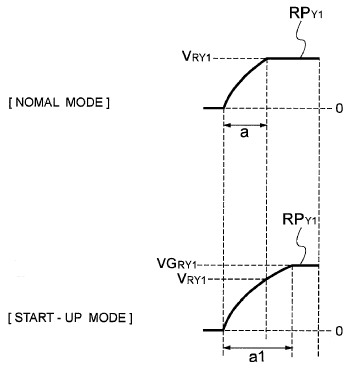
The Figure illustrates the application of a pulse with larger maximum value during the initialising phase in a start-up mode after the powering on of a plasma display panel than in a normal mode.
Classification is to be made in this group if a discharge for priming, i.e. for generating charges in the discharge cell, is generated at the time of powering up the display or at regular intervals.
This place covers:
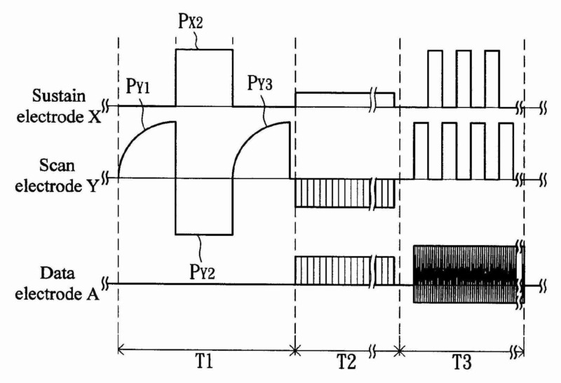
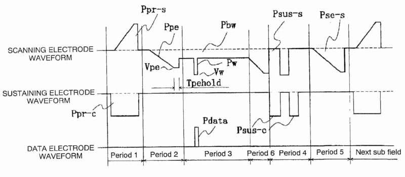
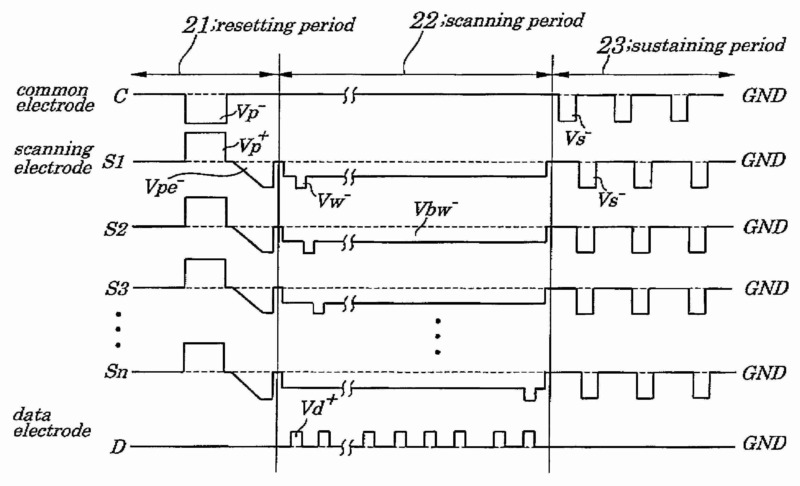
Control of displays using luminous gas-discharge cells as display elements arranged in a matrix in an AC panel with details of the control of the gas-discharge cell or the shape of the pulses applied to the electrodes of the gas-discharge cell for generating a reset discharge, i.e. for initialising the gas-discharge cell as a preparation of the subsequent addressing phase.
Illustrative example of subject matter classified in this place:
The Figure illustrates the application of pulses with rising and falling slope to the scan and sustain electrode during a reset phase for generating discharges in order to provide the same wall charge conditions in all the discharge cells as a preparation for the subsequent addressing phase.
Classification is to be made in this group if a reset discharge, i.e. for initialising the gas-discharge cell as a preparation of the subsequent addressing phase, is generated during every sub-frame, every frame or every multiple frames.
This place covers:
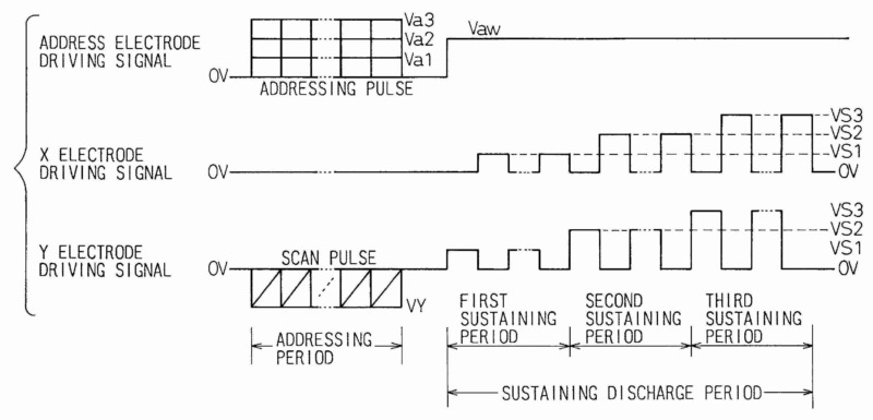
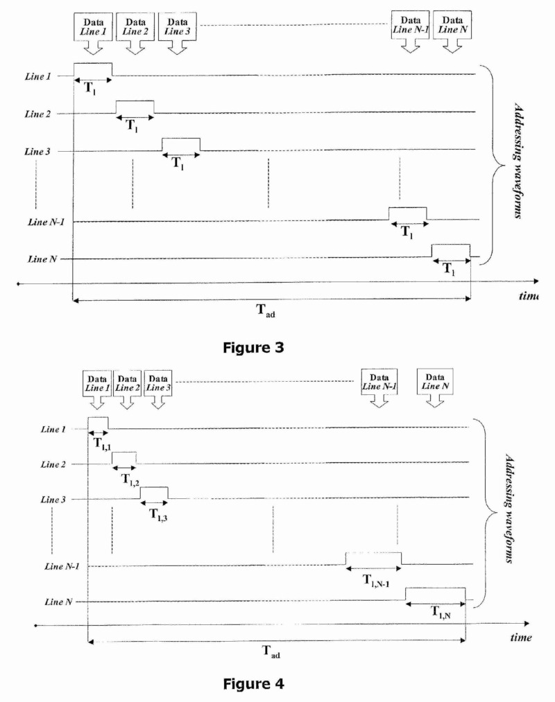
Control of displays using luminous gas-discharge cells as display elements arranged in a matrix in an AC panel with details of the control of the gas-discharge cell or the shape of the pulses applied to the electrodes of the gas-discharge cell for generating an address discharge, i.e. an discharge for selecting the discharge cell according to the display data so that a sustain discharge with light emission takes place in the subsequent sustain phase corresponding to the selection in the addressing phase.
Different control or pulse shapes for different sub-frames are to be indicated by the code G09G 3/2022.
This place covers:
Control of displays using luminous gas-discharge cells as display elements arranged in a matrix in an AC panel with details of the control of the gas-discharge cell or the shape of the pulses applied to the electrodes of the gas-discharge cell for generating an address discharge, wherein the generation of the address discharge generates sufficient wall charges in the addressed cell so that a sustain discharge with light emission takes place in the subsequent sustain phase.
Different control or pulse shapes for different sub-frames are to be indicated by the code G09G 3/2022.
Illustrative examples:
US2003/0102814 (a discharge generated selectively only in those discharge cells during an addressing phase having a pulse applied to the address electrode together with a pulse applied to the scanning electrode generates wall charges, which enable a lighting discharge in these selected cells during the subsequent sustaining phase)
This place covers:
Control of displays using luminous gas-discharge cells as display elements arranged in a matrix in an AC panel with details of the control of the gas-discharge cell or the shape of the pulses applied to the electrodes of the gas-discharge cell for generating an address discharge, wherein the generation of the address discharge reduces or erases the wall charges in the addressed cell so that no sustain discharge with light emission takes place in the subsequent sustain phase.
Different control or pulse shapes for different sub-frames are to be indicated by the code G09G 3/2022.
Illustrative examples:
EP0866439 (after generating wall charges in all the discharge cells during the initialisation phase, a discharge erases the wall charges selectively only in those discharge cells during an addressing phase having a pulse applied to the address electrode together with a pulse applied to the scanning electrode, which disables a lighting discharge in these selected cells during the subsequent sustaining phase)

This place covers:
Control of displays using luminous gas-discharge cells as display elements arranged in a matrix in an AC panel with details of the control of the gas-discharge cell or the shape of the pulses applied to the electrodes of the gas-discharge cell for generating an address discharge, wherein the generation of the address discharge takes place only in one sub-frame of a frame
Illustrative examples:
US2002/0036603 (as the resetting operation is performed only in the first sub-frame, in the following sub-frames only discharge cells not addressed by erasing in the preceding sub-frames can be selected in the addressing phase of a sub-frame by erasing to no longer emit light in the sustaining phase of the sub-frame and all the further sub-frames of the frame)
This place covers:
Control of displays using luminous gas-discharge cells as display elements arranged in a matrix in an AC panel with details of the control of the gas-discharge cell or the shape of the pulses applied to the electrodes of the gas-discharge cell for generating an lighting or sustain discharge, i.e. a discharge for lighting the discharge cells selected during the addressing phase, wherein after the discharge enough charges remain in the cell to generate a further discharge with the next pulse of the same shape, and wherein, if an image having intermediate tones is generated by using sub-frames, the number of lighting discharges corresponds to the grey scale bit of the sub-frame.
Different control or pulse shapes for different sub-frames are to be indicated by the code G09G 3/2022.
This place covers:
Control of displays using luminous gas-discharge cells as display elements arranged in a matrix in an AC panel with details of the control of the gas-discharge cell or the shape of the pulses applied to the electrodes of the gas-discharge cell for generating an lighting or sustain discharge, wherein the luminous efficiency of the panel is increased by applying special waveforms, for instance by waveforms generate two luminous discharges with a single pulse.
Different control or pulse shapes for different sub-frames are indicated by the code G09G 3/2022.
Illustrative examples:
US2002/0008680 (increase of the luminous efficiency by generating a light emitting discharge with the rising and the falling slope of each sustaining pulse)

This place covers:
Control of displays using luminous gas-discharge cells as display elements arranged in a matrix in an AC panel with details of the control of the gas-discharge cell or the shape of the pulses applied to the electrodes of the gas-discharge cell for generating an lighting or sustain discharge, wherein the frequency of the sustain pulses or the number of sustain pulses is varied by the same factor for each subfield of a frame.
Illustrative examples:
EP1065645 (variation of the sustain pulse number with the same factor for all the sub-frames)
This place covers:
Control of displays using luminous gas-discharge cells as display elements arranged in a matrix in an AC panel with details of the control of the gas-discharge cell or the shape of the pulses applied to the electrodes of the gas-discharge cell for generating an lighting or sustain discharge, wherein the frequency of the sustain pulses or the number of sustain pulses is varied for at least one subfield of a frame differently from the other subfields of the frame.
Illustrative examples:
US2005/0219158 (variation of the sustain frequency for a sub-frame according to the display load of the sub-frame, i.e. the number of cells to emit light during the sub-frame)
This place covers:
Control of displays using luminous gas-discharge cells as display elements arranged in a matrix in an AC panel with details of the control of the gas-discharge cell or the shape of the pulses applied to the electrodes of the gas-discharge cell for generating an lighting or sustain discharge, wherein the time period available for the sustaining phase is increased with respect to other time periods in the frame, e.g. pulses in the initialising phase or the addressing phase are modified in order to shorten the time periods needed for these phases and thus enable an increase in light emission by a longer time period for the sustain phase.
Illustrative examples:
EP1365382 (shorter addressing and scanning pulses for addressing the upper scanning lines saves time available for the sustain phase)
This place covers:
Details of a drive circuit for applying pulses to the electrodes of displays using luminous gas-discharge cells as display elements arranged in a matrix in an AC panel.
This place covers:
Details of a drive circuit for applying pulses to the electrodes of displays using luminous gas-discharge cells as display elements arranged in a matrix in an AC panel, which uses inductors in a circuit for recovering the energy from the electrodes of the display.
Illustrative example of subject matter classified in this place:
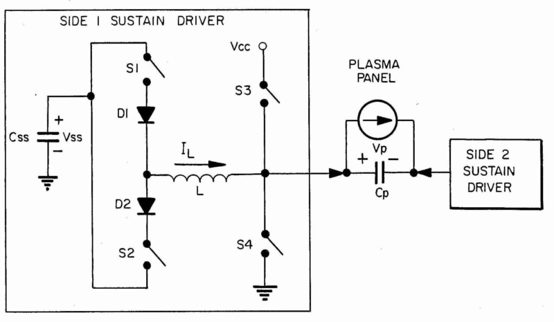
The Figure illustrates a sustain electrode drive circuit with energy recovery circuit using an inductor.
This place covers:
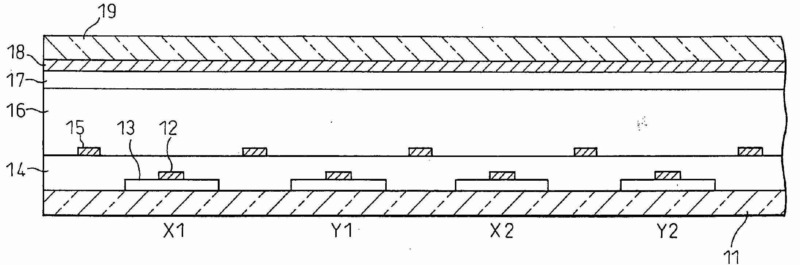
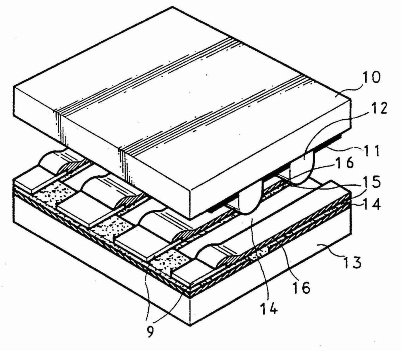
Control of displays using luminous gas-discharge cells as display elements arranged in a matrix in an AC panel, wherein in a discharge cell the electrodes that play a role during the sustain discharge are opposite to each other.
Illustrative examples:
US2007/0171174 (control of AC plasma display panel with address electrodes on a substrate as well as scan and sustain electrodes in the cell walls and opposite to each other)
This place covers:
Control of displays using luminous gas-discharge cells as display elements arranged in a matrix in an AC panel, wherein in a discharge cell the electrodes that play a role during the sustain discharge are on the same surface.
For documents published after 1997 this code is only to be given if no other class under G09G 3/288 is given for a surface discharge panel, as most of the documents after 1997 concern surface discharge panels anyway.
This place covers:
Control of displays using luminous gas-discharge cells as display elements arranged in a matrix in an AC panel, wherein in a discharge cell the electrodes that play a role during the sustain discharge are on the same surface, and the discharge cell electrodes have a non-standard arrangement.
This place covers:
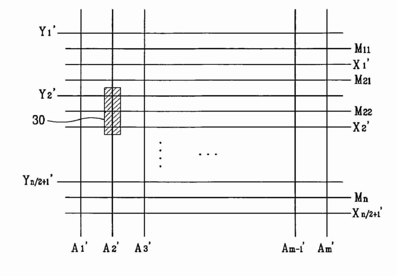
Control of displays using luminous gas-discharge cells as display elements arranged in a matrix in an AC panel, wherein in a discharge cell the electrodes that play a role during the sustain discharge are on the same surface, and with more than three electrodes involved in the operation of the discharge cell.
Also if a neighbouring electrode is involved in the operation of the discharge cell beside the three electrodes corresponding to the discharge cell, such a document is to be classified in this group.
Illustrative examples:
US2005/0116899 (operation of the discharge cell by signals applied to four electrodes, A, M, X, Y)
This place covers:
Control of displays using luminous gas-discharge cells as display elements arranged in a matrix in an AC panel, wherein in a discharge cell the electrodes that play a role during the sustain discharge are on the same surface, and with alternate lighting of the cells of one row and in even columns, and an adjacent other row and in odd columns.
Illustrative examples:
EP1199701 (using all the discharge gaps between the scan and sustain electrodes enables a reduction of the number of electrodes and thus a cost reduction, but requires alternate lighting of the odd and even lines)
This place covers:
Control of displays using electroluminescent display elements arranged in a matrix.
Attention is drawn to the following places, which may be of interest for search:
Control of displays using electroluminescent display elements for displaying a character composed by a fixed number of display elements as segments or dots |
Examples:
US5973456 (application of AC signal generates light in electroluminescent display elements)
This place covers:
- Control of displays using electroluminescent display elements, which are semiconductor devices, e.g. diodes or transistors, arranged in a matrix without details of the semiconductive material.
- Control of displays using electroluminescent display elements, which are semiconductor devices, e.g. diodes or transistors, arranged in a matrix, wherein the semiconductive material is inorganic.
Attention is drawn to the following places, which may be of interest for search:
Control of displays using electroluminescent display elements, which are semiconductor devices, e.g. diodes or transistors, for displaying a character composed by a fixed number of display elements as segments or dots |
This place covers:
Control of displays using organic electroluminescent display elements, which are semiconductor devices, e.g. diodes or transistors, arranged in a matrix, wherein the semiconductive material is organic.
Attention is drawn to the following places, which may be of interest for search:
Control of displays using electroluminescent display elements, which are semiconductor devices, e.g. diodes or transistors, for displaying a character composed by a fixed number of display elements as segments or dots | |
Details of the drive circuits for applying the scan signals to the scan electrodes of an organic electroluminescent matrix display | |
Details of the drive circuits for applying the data signals to the data electrodes of an organic electroluminescent matrix display | |
Organic light-emitting devices [OLED] | |
Integrated devices, or assemblies of multiple devices, comprising at least one organic light-emitting element | |
Integrated devices, or assemblies of multiple devices, comprising at least one organic light-emitting element and at least one organic radiation-sensitive element |
This code is to be given only if no details of the control of the display elements are specified, otherwise the codes of G09G 3/3216 for a passive matrix, or within G09G 3/3225 for an active matrix apply.
This place covers:
Control of displays using organic electroluminescent display elements arranged in a matrix, wherein each display element is located at the intersection of a scan and a data electrode, and directly controlled by the scan and data signal supplied to the scan and data electrode, respectively, i.e. without an active element such as a diode (other than the light-emitting one), or a transistor at the intersection being involved.
The figure below is an example of a passive matrix. In the figure, passive matrix is characterized as having a line driving method which lights all light-emitting devices of the line at once, and a matrix is a 2-dimensional arrangement, comprising cathode and anode strips.
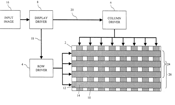
The figure below is an example of selective application of a current to the anodes of OLED display elements as data signal via data electrodes Ak while a voltage is supplied to the cathodes of the display elements as scan signal via scan electrodes.
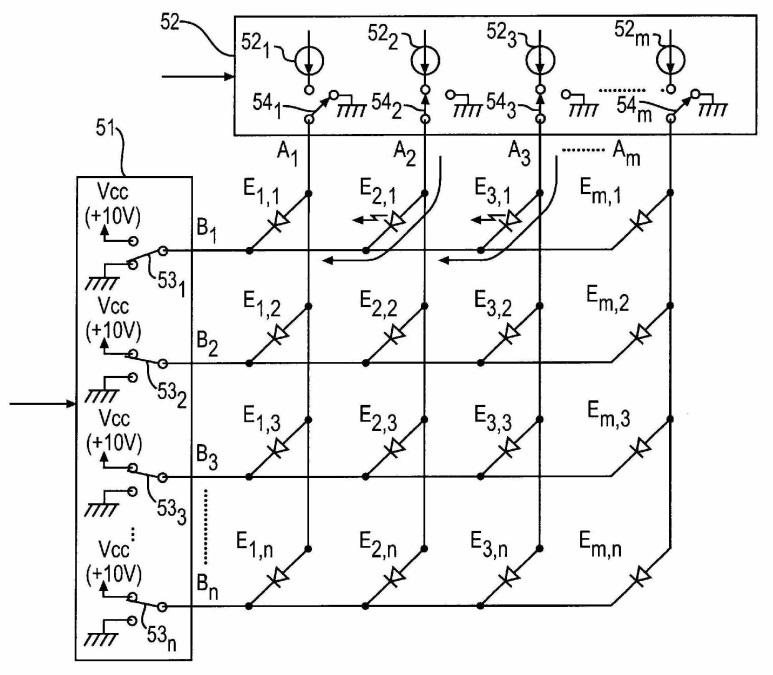
Attention is drawn to the following places, which may be of interest for search:
Details of the drive circuits for applying the scan signals to the scan electrodes of an organic electroluminescent matrix display | |
Details of the drive circuits for applying the data signals to the data electrodes of an organic electroluminescent matrix display |
This place covers:
Control of displays using organic electroluminescent display elements arranged in a matrix, wherein each display element is located together with an active element such as a transistor or a diode, other than the light-emitting one, at the intersection of a scan electrode and a data electrode. The active element has to be enabled by the application of a scan signal to the scan electrode so that the display element receives the data signal.
The figure below is an example of an active-matrix. In the figure, active-matrix is an individual driving method where light-emitting devices are turned on by each film transistor (TFT), and a matrix is an arrangement of light-emitting devices or TFTs or their combinations.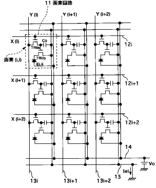
Attention is drawn to the following places, which may be of interest for search:
Details of the drive circuits for applying the scan signals to the scan electrodes of an organic electroluminescent matrix display | |
Details of the drive circuits for applying the data signals to the data electrodes of an organic electroluminescent matrix display |
This place covers:
Control of displays using organic electroluminescent display elements arranged in a matrix together with active elements, wherein each active element enables a driving current flowing through a display element corresponding to a data signal supplied to a data electrode. The corresponding active element must concurrently be selected by a scan signal supplied to its scan electrode.
The figure below is an example of data voltage signal supplied to the data line (14), which controls the driving current flowing through the organic electroluminescent display element.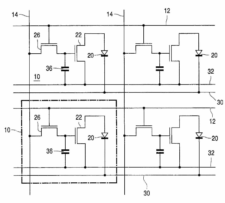
Attention is drawn to the following places, which may be of interest for search:
Details of the drive circuits for applying the scan signals to the scan electrodes of an organic electroluminescent matrix display | |
Details of the drive circuits for applying the data signals to the data electrodes of an organic electroluminescent matrix display |
This place covers:
Control of displays using organic electroluminescent display elements arranged in a matrix together with active elements, wherein each active element enables a driving current flowing through a display element corresponding to a data current supplied to a data electrode, which is supplied when the active element is activated by a scan signal supplied to a scan electrode, e.g. by a current mirror having the data current flowing through the data electrode as an input current, and the driving current flowing through the display element as an output current.
The figure below is an example of data current signal supplied to the data line DL and flowing through the input part PM2 of a current mirror circuit, which controls the driving current flowing through the output part PM1 of the current mirror circuit and the organic electroluminescent display element)
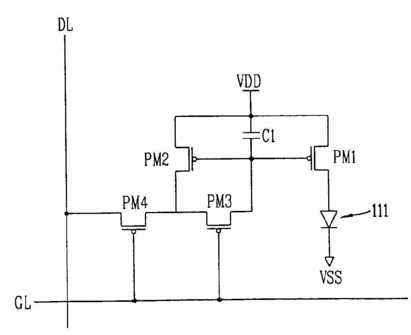
This place covers:
Control of displays using organic electroluminescent display elements arranged in a matrix together with active elements, wherein each active element enables a driving current flowing through a display element corresponding to a data current flowing through a data electrode and through a driving transistor, but not through the display element connected in series with the driving transistor, during a first period when the active element is activated by a scan signal supplied to a scan electrode, and with the driving current flowing through the driving transistor and the display element during a second period when the scan signal is not supplied to the scan electrode, e.g. by a first switch connecting the driving transistor to the data electrode during the first period, and a second switch connecting the driving transistor to the display element during the second period.
The figure below is an example where the data current signal Idat is applied to the data line and flows only through the driving transistor T2 during the scan period (T1 and T3 ON, T4 OFF), and through the driving transistor and the organic electroluminescent display element after the scan period (T1 and T3 OFF, T4 ON).
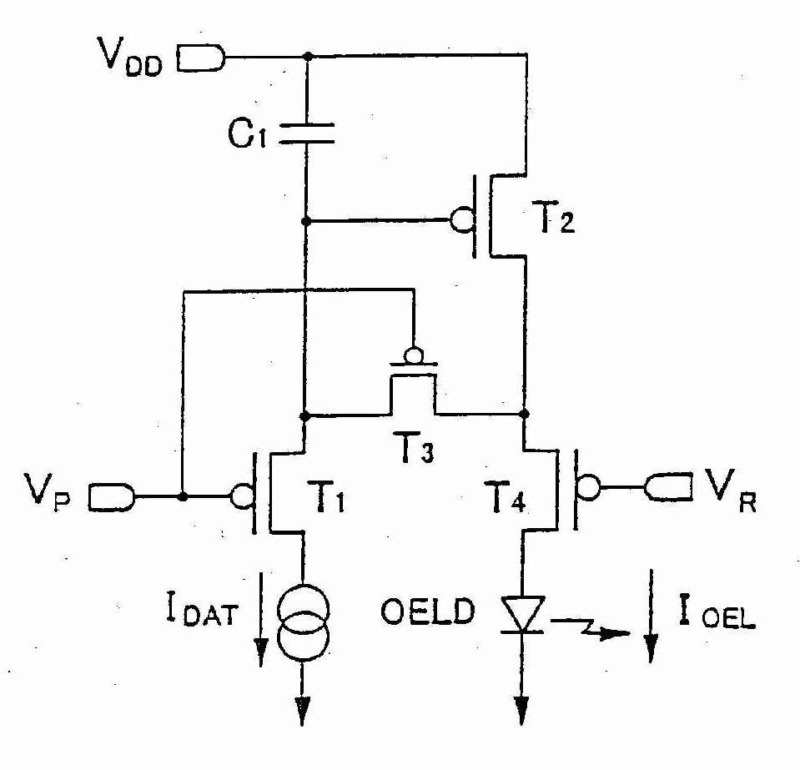
This place covers:
Control of displays using organic electroluminescent display elements arranged in a matrix together with active elements, wherein each active element enables the application of a voltage across a display element corresponding to a data signal supplied to a data electrode. The corresponding active element must concurrently be selected by a scan signal supplied to a scan electrode.
The figure below is an example where the application of a scan signal on a line, 7-j (1<=j<=m), enables the transistors of pixels belonging to that line. The light-emitting diodes of the line can then receive data by supplying a data signal on column 6-k (1<=k<=n).
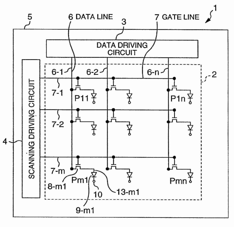
This place covers:
Details of a drive circuit for supplying scan signals to scan electrodes of an organic electroluminescent matrix display.
This place covers:
Details of a drive circuit for supplying data signals to data electrodes of an organic electroluminescent matrix display.
This place covers:
Details of a drive circuit for supplying data signals to data electrodes of an organic electroluminescent matrix display, the data signals being in the form of a variable data current value according to the data to be displayed.
This place covers:
Details of a drive circuit for supplying data signals to data electrodes of an organic electroluminescent matrix display, the data signals being in the form of variable data voltage value according to the data to be displayed.
This place covers:
- Passive displays reflecting or modulating the incident light.
- Displays comprising a passive and an active panel.
Attention is drawn to the following places, which may be of interest for search:
Indicating arrangements for variable information in which the information is built-up on a support by selection or combination of individual elements | |
Characterised by the form or geometrical disposition of the individual elements, i.e. of the multi- segment-display | |
Being the ends of optical fibres | |
Being LCDs | |
Being movable elements |
Examples:
US4170772
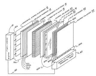
US4170771
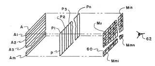
This place covers:
- Control of the independent light source illumination the matrix display (front and backlight).
- Standard field sequential colour displays without specific details.
- One or more separately controlled illumination sources, without correspondence to different display areas.
Illustrative examples of subject matter classified in this place:
1.
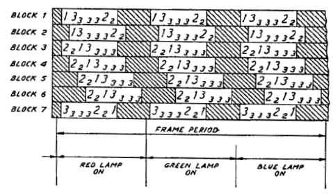
Figure 1 illustrates a standard field sequential display without specific details.
2.

3.
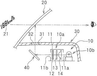
Figure 3 illustrates two illumination sources without corresponding display areas.
This place does not cover:
Illumination devices structurally associated with liquid crystal cells |
Attention is drawn to the following places, which may be of interest for search:
Light sources using semiconductor devices as light-generating elements, e.g. using light-emitting diodes [LED] or lasers | |
Light guides specially adapted for lighting devices or systems. | |
Inverters for backlight units: conversion of DC power input into DC power output. | |
Inverters for backlight units: conversion of AC power input into DC power output. | |
Constructional details of illumination within telephone sets. | |
Projection devices for colour picture display in colour television systems using light modulating optical valves. | |
Control of light sources in general (i.e., not specifically related to a display device). | |
Circuit arrangements for operating light sources in general, i.e. where the type of light source is not relevant |
Classification as additional information is obligatory in the following indexing codes: G09G 2310/0235, G09G 2310/024, G09G 2320/06, G09G 2320/0613, G09G 2320/062, G09G 2320/0626, G09G 2320/0633, G09G 2320/064, G09G 2320/0646, G09G 2360/14, G09G 2360/144, G09G 2360/145 or G09G 2360/16.
This place covers:
- Control of backlight arrangements with more than one colour.
- Specific details of control of sequential colour displays.
Further detail is covered by the Indexing Code symbols listed below. Classification is obligatory.
To indicate details of the colour setup of elements in an array of light emitting elements forming the illumination source: G09G 2300/0452
Example:
US2004246275 (Filed sequential display with specific details)
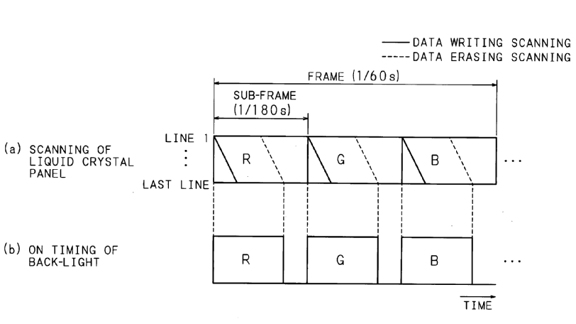
US6608614 (Automatic adjustment of colour parameters)
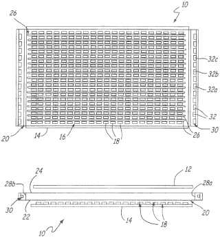
This place covers:
Documents disclosing horizontal stripes or rows of pixel, each lit by a separate illumination source, each illumination source being independently controlled from the other illumination sources.
Illustrative examples:
US2002000960 (Backlight with scanning of illumination source)
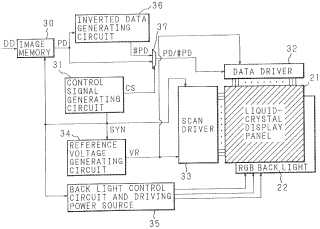
WO2005093703 (Backlight without scanning of illumination source)
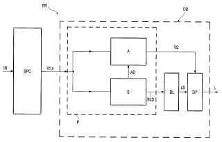
US6563271 (Backlight having separate light sources for different panel regions)

This place covers:
Documents disclosing a backlight unit usually comprising a matrix of pixel blocks or single pixels which are each lit by an separate illumination source, each illumination source being independently controlled from the other illumination sources.
Illustrative examples:
EP1380876 (Backlight unit with scanning of illumination sources)
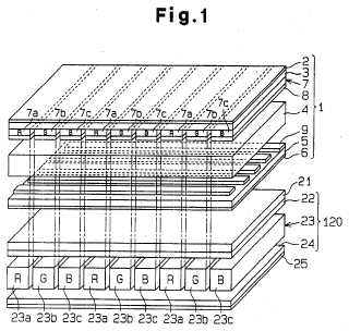
US2001028335 (Backlight unit without scanning of illumination source, with S09206/02 Indexing Code)
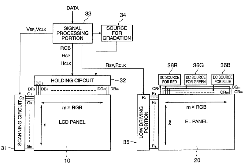
EP1496497 (Display comprising stacked panels, with S09206/02 Indexing Code)
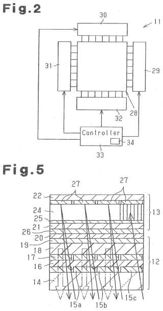
Attention is drawn to the following places, which may be of interest for search:
Control arrangements for presentation of an assembly of a number of characters, e.g. a page, by composing the assembly by combination of individual elements arranged in a matrix, by control of light from an independent source, using liquid crystals | |
Control arrangements for presentation of an assembly of a number of characters, e.g. a page, by composing the assembly by combination of individual elements arranged in a matrix, by control of light from an independent source, using electrochromic devices |
Illustrative examples:
EP0291122 (Electroscopic display)
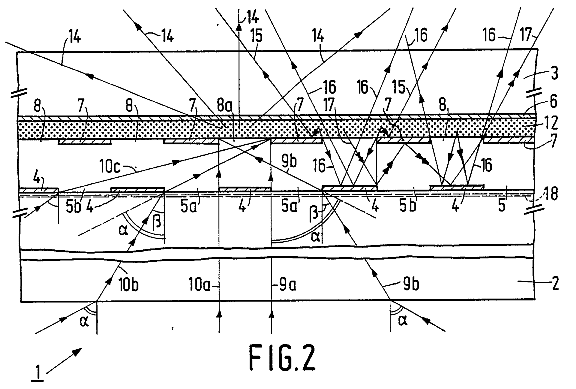
GB1205236 (Contrast liquid is moved to activate selected pixel cells)
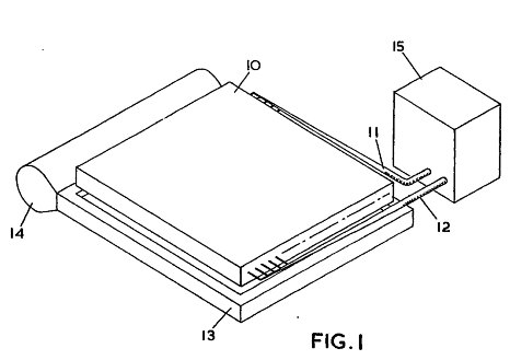
EP0153178 (Electrostatic display)
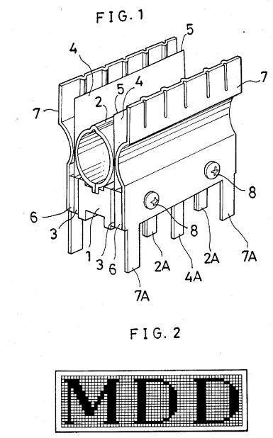
WO2006091738 (Electrostatic display)
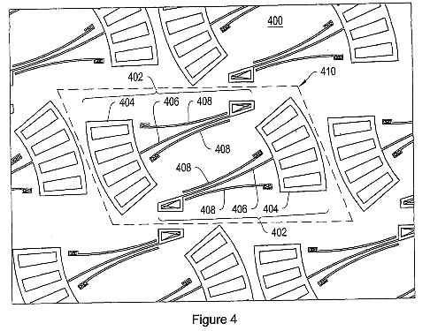
This place covers:
Control of display devices wherein the visual effect is obtained by controlling the displacement of microparticles in fluid or gas.
This place does not cover:
Electrophoretic devices per se |
Example:
US4041481 (Electrophoretic display device)
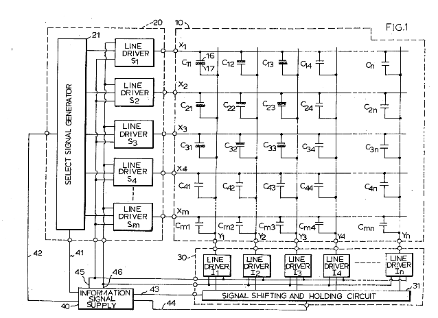
This place covers:
Documents in which the displacement of the microparticles is obtained with a cell electrode structure comprising more than two electrodes.
Illustrative example:
US5223115 (Item 26: cathode, item 18: anode, item 28: grid)
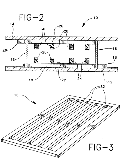
This place covers:
Control of display devices with rotating elements ("particles") that are encapsulated and suspended in a fluid and controlled by electrostatic operation.
Also control of displays wherein each pixel contains a plurality of "particles" (e.g. "Gyricon®" from Xerox).
Attention is drawn to the following places, which may be of interest for search:
Optical devices or arrangements using movable or deformable optical elements for controlling the intensity, colour, phase, polarisation or direction of light (e.g. switching, gating, modulating) | |
For controlling the intensity of light based on the rotation of particles under the influence of an external field. | |
Macro displays |
Illustrative example of subject matter classified in this group:
US2006214880
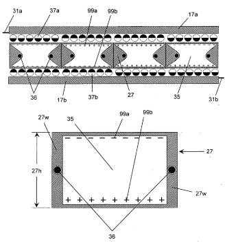
In this place, the following terms or expressions are used with the meaning indicated:
E-Paper | Electric(al) or electronic (reusable) paper |
In patent documents, the following words/expressions are often used as synonyms:
- "Gyricon® ", "rotating ball", "twisting ball", "rotating particle" and "twisting particle"
This place covers:
- Electrostatically controlled micromirrors.
- Rocking DMD.
- Bending reflective "tongues").
This place does not cover:
Micromirrors devices per se |
Attention is drawn to the following places, which may be of interest for search:
Micromechanical (e.g. MEMS) devices comprising elements which are flexible, deformable or movable (e.g. slidable or rotatable) in relation to each other | |
Piezoelectric, electrostrictive or magnetostrictive elements per se |
Illustrative examples of subject matter classified in this group:
US5214419
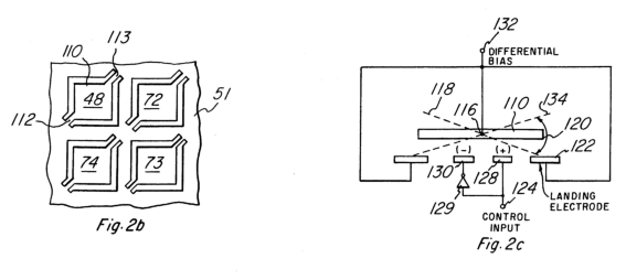
In this place, the following terms or expressions are used with the meaning indicated:
MEMS | Microelectromechanical system |
NEMS | Nanoelectromechanical system |
DMD | Deformable Mirror device - Digital mirror device |
DMM | Digital micromirrors |
DLP | Digital light processing |
This place covers:
Control of electrically switched displays composed of miniature interferometers (etalons) that are switched on and off with microelectromechanical systems. An etalon reflects light at a specific wavelength and gives pure, bright colours while consuming no power.
Attention is drawn to the following places, which may be of interest for search:
Devices or arrangements using multiple reflections in spectrometry or monochromators (Fabry-Perot interferometers) | |
Interference filters | |
Optical modulators based on interference in an adjustable optical cavity |
Illustrative examples of subject matter classified in this group:
EP1473581
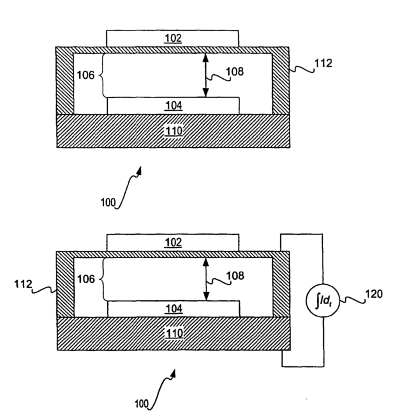
US2002054424
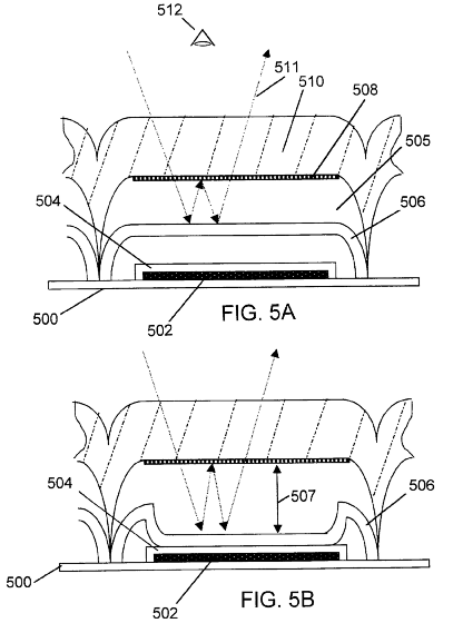
Interferometric modulator [IMOD], Diffractive light device [DLD].
This place covers:
Illustrative example of subject matter classified in this group:
WO9731288
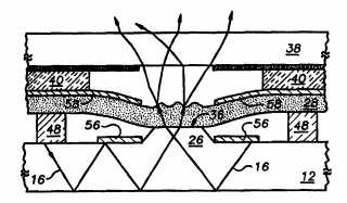
This place covers:
Movable elements controlled electromagnetically (also: magnetostrictive effect used in "foil" display).
Illustrative example:
DE2133121
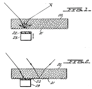
This place covers:
Illustrative example of subject matter classified in this group:
EP1369844 (Piezoelectric actuator in combination with scattering of light from a waveguide. In this case the document was allocated both G09G 3/3493 and G09G 3/3473 symbols)
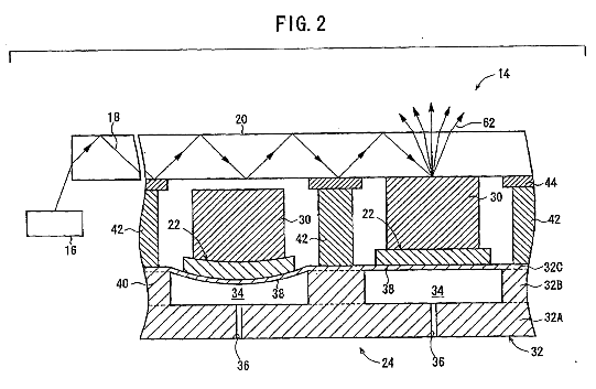
This place covers:
Control of discrete pixel electrodes on one substrate without row and column selection.
Control of a plurality of display modules combined to result in a bigger matrix.
Address matrix for selecting a row or column.
Specific circuits for crosstalk compensation (e.g. with extra electrode carrying an additional signal).
Circuit for temperature compensation in LC displays.
Control of stacked LC panels.
Attention is drawn to the following places, which may be of interest for search:
Chemical composition of LCD | |
Constructional arrangements; Operation of LCD; (arrangements or circuits for control of liquid crystal elements in a segment display or a matrix ) |
Attention is drawn to the following places, which may be of interest for search:
Multi colour thermography | |
Liquid crystal cells exhibiting a thermo-optical effect |
This place covers:
Control of subpixels in liquid crystal displays.
This place does not cover:
Display of colours in flat matrix panels other than liquid crystal displays. | |
Gray scales specific for television systems |
This place covers:
- Control of liquid crystal displays wherein the type of matrix (active, passive) is not defined.
- Addressing of liquid crystal matrices in general (e.g. without specifying waveforms, information transfer computer ==> memory ==> panel, driver circuits).
- Control of a liquid crystal panel by computer signals or composite signals.
- Overview articles.
- Timing circuits.
- Black on white of white on black displays.
Illustrative examples: US2005174456 (Interface from external camera or host to a LCD, wherein the display data are stored in the display driver. The display controller communicates with the display unit sending RGB-data and the LCD-clock. Because no hsync / vsync are transmitted, this interface does not form a monitor_architecture)
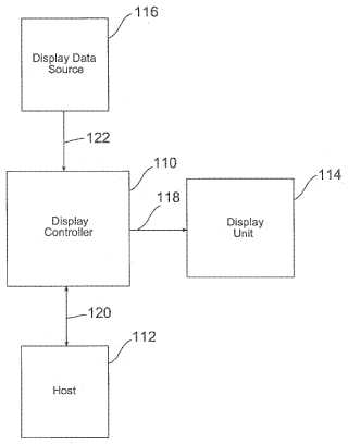
FR2808113 (Details of wiring between drivers and rows and columns)
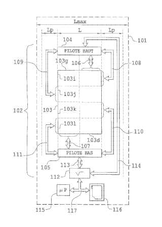
This place covers:
- Specific control circuits for polarity inversion in LCD display devices.
- Inversion sequences (row-, column-, field-, dot-inversion).
Attention is drawn to the following places, which may be of interest for search:
Control of polarity inversion for display devices other than LCD devices |
This place covers:
Control of passive matrix devices. Passive matrix means that there are no active elements (transistor, diode, MIM, ...) in the display cell at the crosspoint of a row and column.
This place does not cover:
Detail of drivers for scan electrodes | |
Detail of drivers for data electrodes | |
Generation of voltages supplied to electrode drivers |
This place covers:
In traditional multiplexing, the rows are addressed in sequence and only one at a time. The voltages set on the columns correspond to the pixel values in the row being addressed. This scheme leads to very low voltage selection ratios and, consequently, low contrast.
In the Active Adressing scheme, several rows are addressed simultaneously in different patterns corresponding to orthogonal functions. A set of functions is orthogonal over a certain interval if the integral of the product of any two of the functions is 0 if the functions are different, and a constant if they are the same function. From signal processing theory, we can represent a given signal as a sum of differing amounts of these orthogonal functions. If we suppose the signal we wish to represent is the sequence of pixel values in a particular column of a display, then we can create that signal by applying the correct orthogonal functions to the row lines and certain voltages on the column line that correspond to the amounts of those functions we want. If we use the same functions to represent the signals in the other columns, then we can create a whole display by applying the correct voltages to all of the column lines in parallel.
Documents classified in G09G 3/3625 shall not receive an Indexing Code for active addressing (G09G 2310/0208 ).
Illustrative example:
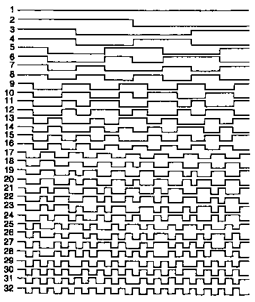
Order 32 Walsh functions. These kinds of functions serve as the voltage settings for the row lines in active addressing.
This place covers:
Control of:
- ferroelectric LCDs, i.e. LCs having a polarization vector, that causes an inherent memory effect, shown in a single memory loop in the transmission/voltage characteristic has, such as chiral smectic LCs.
- Nematic LCDs (chiral nematic) where two metastable states are obtained by others means.
- LCDs using a "type" transition to obtain memory effects (nematic - cholesteric).
Attention is drawn to the following places, which may be of interest for search:
Details of waveforms for flat panels | |
Partial updating | |
Chemical composition of ferroelectric liquid crystals | |
Physics and structure of LCDs |
Examples:
US4793693
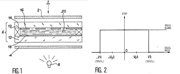
US4367924
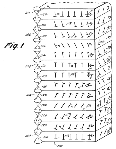
US4715688
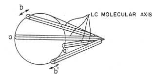
US5594464 (nematic LCD where two metastable states are obtained by disrupting molecule anchoring with an initial pulse; in this case apply also Indexing Code G09G 2300/0486 ).
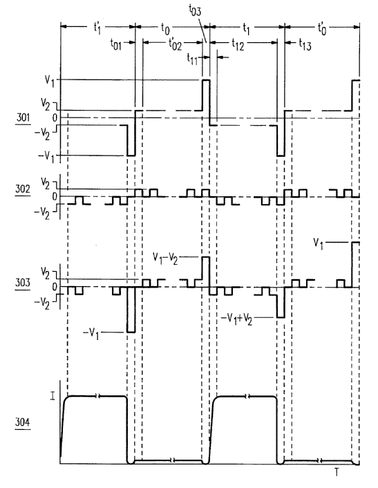
US4395709 (Guest-host solutions)
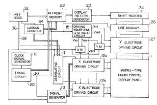

US4902105 (Dynamic scattering smectic LC of positive dielectric anisotropy)
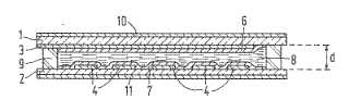
EP957394 (nematic-cholesteric LCDs with planar and focal conic states)
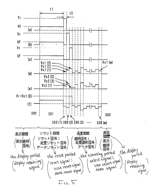
This place covers:
Control of:
- Antiferroelectric LCDs having two antiferroelectric states for positive and negative pixel voltages and a ferroelectric state without pixel voltage, both with symmetric or asymmetric loops, where memory effects are desired and used.
- Short pitch ferroelectric LCDs [SBF LCDs] where the helix pitch is shorter than the pixel cell thickness.
This place covers:
- Control of LCDs having memory effect (e.g. ferroelectric) where gradation is obtained by varying the extension of the pixel area where switching from one memory state (e.g. ferroelectric state) to the other takes place, e.g. by.
- Arranging the electrodes such to vary the applied voltage across the pixel, so that a gradient in the LC electric field is obtained.
- Varying the thickness of the LC cell across the pixel.
- Simply using unevenness in the LC cell structure.
Attention is drawn to the following places, which may be of interest for search:
Domain size control in flat matrix panels other than liquid crystal displays having memory effects |
Example:
US2006244698
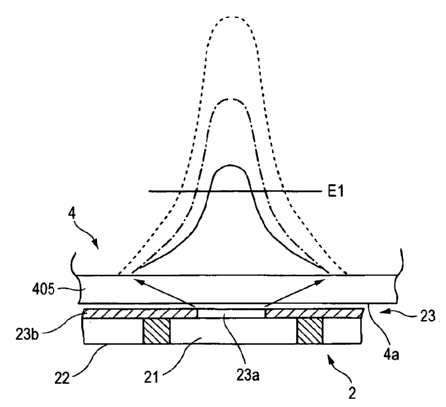
This place covers:
Using subpixels in memory effect LCDs for displaying gradations (common solution, together with subframe modulation, since the memory effect LCDs are normally binary devices) or for other purposes.
Attention is drawn to the following places, which may be of interest for search:
Gradation display by the use of subpixels in general (in all sorts of matrix displays beside passive matrix LCDs) | |
Layout of subpixels used for reasons other than gradation display | |
Details of colour pixel setup, e.g. pixel composed of a red, a blue and two green components |
Documents classified in G09G 3/364 shall not receive an Indexing Code for subpixels addressing (G09G 2300/0439 and subgroups).
Video-walls, which consist out of modules, meant to be flexibly combined into a bigger size display, e.g. for installation or configuration purposes (see G06F 3/1446 and G09G 2300/026).
Matrices where the split has no impact on the driving, i.e. it is just a convenient constructional measure or it serves other purposes (heat dispersion etc.). Possible classifications for such cases are again in G06F 30/00, H10D 86/60, or in groups related to the physical structure of specific display technologies (e.g. G02F 1/13 for LCDs).
Splitting of matrices in a way that the resulting structure cannot be driven independently from each other, e.g. driving odd lines from one driver and even lines from another driver.
This place covers:
Control of image refresh frequency in LC displays, wherein the displays comprise a switching element (e.g. a transistor) in series with the liquid crystal cell at each matrix point.
This place does not cover:
Control of matrices with row and column drivers, with a nonlinear element in series with the liquid crystal cell, e.g. a diode, or M.I.M. element | |
Detail of drivers for scan electrodes | |
Detail of drivers for data electrodes | |
Generation of voltages supplied to electrode drivers |
This place covers:
- Driving circuits for common electrodes of:
- pixels;
- supplementary-capacitors (in this case consider Indexing Code G09G 2300/0876 as well).
- Striped or segmented common electrodes.
- Driving of electrode groups.
- Driving with additional line selector (shift register).
- Use of common electrodes as additional selection line.
- Problems related to resistance or capacity of common electrodes (if compensated via the same).
- Pixel voltage manipulation via common electrode(s).
- Increase pixel voltage (by modifying counter electrode voltage at appropriate time).
- Application of compensation voltages (e.g.: feedthrough, crosstalk, view angle, temperature) via the counter electrodes.
This place covers:
- Pixel selection or control:
- logical AND/OR (in connection with several pixel TFTs)
- via additional gate lines (two per pixel)
- via adjacent gate lines (each gate line used for two pixels)
- Control of D/A converter in pixel (via additional lines)
- Control of variable capacitor in pixel
- Pixel voltage manipulation
- pixel capacitor or supplementary capacitor connected to (or adjacent to)
- GATE line (first gate line selects TFT, second manipulates pixel voltage)
- DATA line (voltage difference on data lines defines pixel voltage)
- pixel voltage defined by voltage between a gate line and a data line
- Redundancy in the driving, precharging or symmetry
- pixel driven twice, once via a first TFT and a first data line, then via second TFT and second data line
- structures with multiple TFTs (multiple redundant selection or data paths).
This place covers:
Illustrative example of subject matter classified in this group:
EP0651368

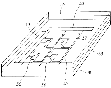
Video-walls, which consist out of modules, meant to be flexibly combined into a bigger size display, e.g. for installation or configuration purposes (see G06F 3/1446 and G09G 2300/026).
Matrices where the split has no impact on the driving, i.e. it is just a convenient constructional measure or it serves other purposes (heat dispersion etc.). Possible classifications for such cases are again in G06F 30/00, H10D 86/60, or in groups related to the physical structure of specific display technologies (e.g. G02F 1/13 for LCDs).
Splitting of matrices in a way that the resulting structure cannot be driven independently from each other, e.g. driving odd lines from one driver and even lines from another driver.
This place covers:
Control of pixel circuits wherein a diode string or a variable resistor is connected in series with the LC cell.
Attention is drawn to the following places, which may be of interest for search:
Scan driver details for non-LCD panels |
Attention is drawn to the following places, which may be of interest for search:
Details of drivers for data electrodes, other than drivers for liquid crystal, plasma or OLED displays |
Documents receiving this code usually do not receive G09G 2310/0275 .
However, documents should be given the following codes in addition to G09G 3/3685, if applicable when they contain the corresponding details:
- Digital gray scale data driver in matrix panels, e.g. including D/A converter G09G 2310/027
- The data driver communicating data to the pixels by means of a current G09G 2310/0272 .
This place covers:
Generation of driving voltages, as distinguished from power supply voltages, to be used by the drivers for the generation of waveforms applied to the electrodes.
Although some of the driving voltages may possibly be coincident with the power supply voltages (normally the extreme voltage values), driving voltages serve the purpose of composing an electrode addressing waveform, rather than supplying power to a functional unit; driving voltages may be representative of gradation levels (AM gradations) or may merely be levels required by a complex waveform (e.g. in the addressing of passive matrix LCDs, FLCDs, electrophoretic panels etc).
The lines/electrodes to which driving voltages are applied may or may not draw power from the generating circuit; driving voltages may normally be regarded as reference voltages, and normally for them only very small fluctuations are tolerated.
The generation of voltages is different than the generation of signals applied to the electrodes.
Illustrative examples:
- US2007046600 (Generation, by means of an arrangement of resistor ladders and selectors of voltages corresponding to gradation levels for an active matrix LCD, that take into account also the required gamma correction; the generated voltages are then selectively applied to the signal lines by the corresponding driver)
- US2008007502 (Charge pumps are used to generated voltage levels used for driving an LCD; not necessarily corresponding to the power supply level of the circuitry, possibly higher)
- WO9100588 (Generation by means of arrangements of resistor ladders, buffers etc., of voltages used in the composition of (possibly) complex waveforms driving rows and columns in a passive LCD)
Attention is drawn to the following places, which may be of interest for search:
Control of e.g. intensity or colour of light based on electrochromic elements |
In this place, the following terms or expressions are used with the meaning indicated:
Electrochromic devices | Comprise one or more electrochromic matrix-elements named cells or pixels or dots, etc, such as information displays. Each element is composed of at least two electrodes that are electrically connected via an ion-conducting medium, i. e. an electrolyte. The elements may change colour if the potential difference between the electrodes is changed. This colour change is caused by redox reactions, i. e. changes in the distribution of electric charge within the element. The colour changes are caused by changes in the spectral absorption and/or emission properties of electromagnetic radiation. With 'colour' we mean also the spectral properties outside the visible region, e.g. in the infrared and the ultraviolet regions. |
This place covers:
Applicable when common to all display technology. By example when display technologies are not specific to LCD but to LCD, Plasma and OLEDS. (also CRTs but it is no more relevant in 2011).
See also image data processing or generation, in general G06T.
This place covers:
Resolving memory contention by CRT controller and the CPU, eventually combined with refresh of the dynamic memory.
Illustrative examples of subject matter classified in this place:
1.
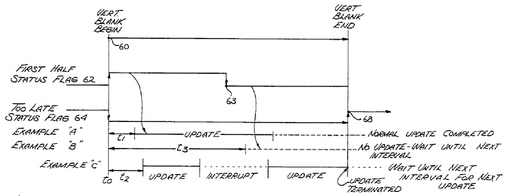
Figure 1 illustrates a bit-map based display system.
2.
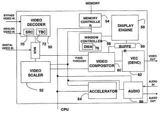
Figure 2 illustrates a display system with video synchronization.
3.
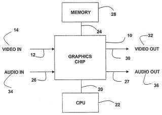
Figure 3 illustrates a display system with blending graphics and video surfaces.
4.
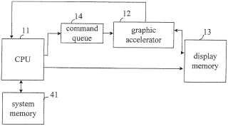
Figure 4 illustrates a method for bitmapping and synchronization.
5.
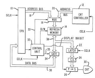
Figure 5 illustrates a character-based display system.
6.
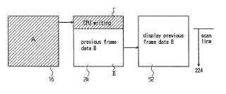
Figure 6 illustrates a display control unit that is both bit-map and character-based.
7a.
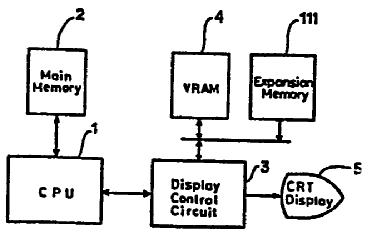
7b.
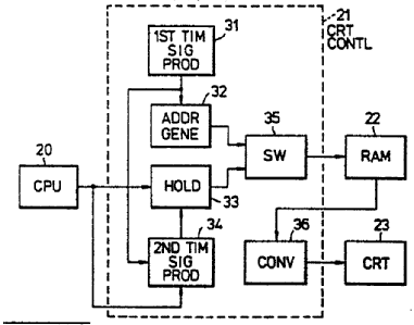
Figures 7a and 7b illustrate a generic display control unit.
Attention is drawn to the following places, which may be of interest for search:
Control of the character-code memory | |
Control of the bit-mapped memory | |
Addressing or allocation within memory systems or architectures |
This place covers:
Details of a display terminal (*1), e.g. details of the display terminal controller, interconnection and interface between display terminal controller and display device controller, buffering of image data, calibration, on-screen display of menu data for setting of parameters, data processing independent of the type of display device.
This place does not cover:
Colour circuits specific for CRT |
Even though the groups G09G 1/165 and G09G 3/2092 still exist, they should be used in very special cases only in which the connection with the technology of the display unit (CRT or flat panel) determines the content of the document.
The codes G09G 5/003 and below apply only if a monitor-architecture can be identified (the same rule applies for G09G 3/2092 and G09G 1/165).
The following groups should also be searched, because they have not yet been purged of documents for G09G 5/003
G09G 3/3611: control of matrices with row and column drivers
G06F 3/147: using display panels
G06F 3/153: using cathode-ray tubes
G09G 1/285: interfacing with colour displays
In this place, the following terms or expressions are used with the meaning indicated:
Display terminal | an apparatus connected to a source of display data (usually a graphics controller of a computer, or directlz to the computer itself) adapted to display images generated by this source of data. In general a "display terminal" is an arrangement including a display device (e.g. a CRT with its driving electronic or a flat panel including its row and column drivers), a display device controller (the hardware and software (usually a microprocessor) that controls the display device and that allows its functioning by, for example, generating the signals that are needed to bring the data to the drivers) and a display terminal controller (the hardware and software used to control the display terminal as a whole and to interface the display terminal to the graphics controller, to adapt data and control signals, for example in an LCD driven by a VGA type graphics controller). |
Attention is drawn to the following places, which may be of interest for search:
Scaling the whole image or part thereof |
The codes G09G 5/003 and below (thus including G09G 5/005) apply only if a monitor-architecture can be identified (the same rule applies for G09G 3/2092 and G09G 1/165).
Used to be a subgroup of G09G 5/006 (now G09G 5/006), this code applies independently of where the adaptiation is done, in the interface or in the controller of the terminal. Most of the documents in this group will relate to flat panels, since a CRT does not need, in general, any adaptation. It was decided, however, to have a single classification for all the documents dealing with this problem.
The output of the interface usually will be a frame or a line buffer, the latter may well be included in the data driver of the visualization unit.
The following groups should also be searched, because they have not yet been purged of documents for G09G 5/005:
G09G 3/3611: control of matrices with row and column drivers
G06F 3/147: using display panels
G06F 3/153: using cathode-ray tubes
G09G 1/285: interfacing with colour displays
Notes on new groups:
G09G 5/006 is former G09G 5/006 and G09G 5/006
G09G 5/005 is former G09G 5/005
G09G 5/008 is former G09G 5/008
This place covers:
Interface between a graphics controller and a display terminal
Illustrative examples:
US2003033417 - A special interface usable with everything, espacially to transmit video (and audio) data to be viualized on a display unit. It includes USB, but a lot more; it can also transmit graphic primitives. Two classes were given, G09G 5/006 and G06F 3/14.
This place does not cover:
Circuits for interfacing with colour displays |
Examples of places in relation to which this place is residual:
Specific for a display terminal using a CRT | |
Specific for a display terminal using a flat panel |
Attention is drawn to the following places, which may be of interest for search:
Interconnection of, or transfer of information or other signals, between memories, I/O devices, or CPUs | |
Real-time session management in data packet switching networks | |
Session management in data packet switching networks | |
Interface between a recording apparatus and a television receiver. |
Documents with interfaces to terminals will be classified in this group unless the structure of the interface is very much tied to the technology of the display (exceptional cases).
The codes G09G 5/003 and below (thus including G09G 5/006) apply only if a monitor-architecture can be identified (click to see definition; the same rule applies for G09G 3/2092 and G09G 1/165).
For picture scaling by changing the sampling timing of the analog signal G09G 5/005 is applied
EP0765078 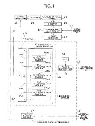
EP0821340 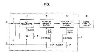
EP1056285 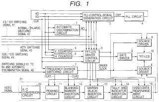
For clock generation (typically by PLL) G09G 5/008 (former G09G 5/008 ) is applied
US6049318 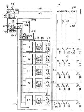
Notes on new groups:
G09G 5/006 is former G09G 5/006 and G09G 5/006
G09G 5/005 is former G09G 5/005
G09G 5/008 is former G09G 5/008
The following groups should also be searched, because they have not yet been purged of documents for G09G 5/005:
G09G 3/3611: control of matrices with row and column drivers
G06F 3/147: using display panels
G06F 3/153: using cathode-ray tubes
G09G 1/285: interfacing with colour displays
This place covers:
Some digital data streams, especially high-speed serial data streams (also for analog signal with hsync and vsync synchro decoding to recreate the pixel clock) are sent without an accompanying clock signal. The receiver generates a clock from an approximate frequency reference, and then phase-aligns to the transitions in the data stream with a phase-locked loop (PLL). This process is commonly known as clock and data recovery (CDR).
In order for this scheme to work, a data stream must transition frequently enough to correct for any drift in the PLL's oscillator. The limit for how long a clock recovery unit can operate without a transition is known as its maximum consecutive identical digits (CID) specification. To ensure frequent transitions, some sort of encoding is used; 8B/10B encoding is very common, while Manchester encoding serves the same purpose.
This group used to be a subgroup of G09G 5/006 (now G09G 5/006; see notes there), this code applies if the clock recovery is performed within the display interface of a monitor-architecture. Most of the documents in this group will relate to flat panels, since a CRT does not need, in general, any adaptation. It was decided, however, to have a single classification for all the documents dealing with this problem.
Notes on new groups:
G09G 5/006 is former G09G 5/006 and G09G 5/006
G09G 5/005 is former G09G 5/005
G09G 5/008 is former G09G 5/008
The following groups should also be searched, because they have not yet been purged of documents for G09G 5/005:
G09G 3/3611: control of matrices with row and column drivers
G06F 3/147: using display panels
G06F 3/153: using cathode-ray tubes
G09G 1/285: interfacing with colour displays