CPC Definition - Subclass G01S
This place covers:
- Methods or apparatus for determining positions, directions and distances by use of radio waves.
- Methods or apparatus for determining velocities of solid objects/bodies by use of radio waves, unless the body is moving relative to some fluid and the influence of the streaming medium on the wave propagating therein is measured.
- Methods or apparatus for locating solid objects/bodies, or detecting their presence by use of reflection or re-radiation of radio waves.
- Methods or apparatus for navigation by use of radio waves (attention is drawn to the limited scope of the term navigation, given below in the section Glossary of Terms).
- Analogous methods or apparatus using other waves than radio waves, e.g. infrared, visible or ultraviolet light, or acoustic waves. Certain restrictions and priorities apply as regards other subclasses (see sections Relationships between larger subject matter areas and References relevant to classification in this subclass below).
- Radar, Lidar, Sonar systems in general and specially adapted for specific applications if not specifically designed for geophysical use.
The general subject matters direction-finding, navigation, determining distances or velocities, locating, or presence-detecting are covered by several subclasses besides G01S such as: G01B, G01C, G01P, G01V.
G01S necessarily requires the use of waves (attention is drawn to the section Glossary of terms).
Therefore, the use of static or time-varying fields that do not obey a wave equation is not sufficient for subject matter to be classified in G01S.
G01S specially emphasizes radio waves. Thus, this subclass is always the appropriate place when radio waves are used for determining directions, bearings, or distances. It is also always appropriate when radio waves are used for determining velocities of solid objects or bodies as well as for locating such bodies or detecting their presence. It is also always appropriate for navigation by using radio waves (attention is drawn to the limited scope of the term navigation, given below in the section Glossary of terms).
As regards the use of other waves than radio waves, the part "analogous arrangements using other waves" of the title requires careful consideration of G01B, G01C, G01P, and G01V that all cover the use of such waves for the measuring of similar variables like distance, velocity, direction, or location.
When propagation effects of waves are relevant (see definition below in the section Glossary of terms), G01B, G01C, and G01P all refer to G01S as being the appropriate place; however, there are some exceptions where propagation effects are relevant but the subject matter is classified elsewhere (see section References relevant to classification in this subclass below).
It is to be noted that this emphasis on propagation effects does not preclude subject matter from being classified in G01S when propagation effects are irrelevant to that subject matter.
Examples of places where the subject matter of this place is covered when specially adapted, used for a particular purpose, or incorporated in a larger system:
Measuring volume flow of fluids or fluid solids by propagation effects of electromagnetic or other waves | |
Measuring direction or velocity of flowing fluids or of solid bodies relative to fluids using propagation effects of waves | |
Radar, Sonar, Lidar, or analogous systems specifically designed for geophysical use | |
Active systems for generating focusing signals | |
Navigation systems for traffic control purposes, i. e. systems in which the navigation is not performed autonomously by or in the vehicles, but where the vehicles are guided by instructions transmitted to them | |
Proximity switches |
Attention is drawn to the following places, which may be of interest for search:
Measuring dimensions or angles of objects | |
Measuring distances by optical means between spaced objects when propagation effects are irrelevant | |
Navigation in general | |
Passive optical systems for measuring distances in line of sight or transverse to line of sight, respectively | |
Navigation not using radio waves when propagation effects are not relevant; navigation beyond position fixing, determining velocity of a vehicle or craft or its direction of velocity | |
Measuring infrasonic, sonic or ultrasonic vibrations in general | |
Measuring infrared, visible, or ultraviolet radiation in general | |
Transducers per se, see the following relevant subclasses | |
Investigating materials by optical radiation, microwaves or acoustic waves | |
Measuring direction or velocity of flowing fluids by reception or emission of radio waves or other waves and based on propagation effects caused in the fluid itself | |
Determining velocities by optical means when propagation effects are not relevant | |
Determining presence, absence, or direction of movement | |
Measuring electric or magnetic variables in general | |
Detecting masses or objects by methods not involving reflection or reradiation of radio, acoustic, or other waves; prospecting | |
Prospecting by optical means; detecting the presence of objects or masses by optical means, e.g. by interruption of beams, i.e. light barriers | |
Optical systems | |
Time-interval measuring | |
Control of position, course, altitude or attitude | |
Detecting the presence of objects for the purpose of counting them | |
Traffic control systems; anti-collision systems | |
Aerials |
In this place, the following terms or expressions are used with the meaning indicated:
Waves | Is the mechanism by which energy is transported without the transfer of matter. Waves may be either electromagnetic waves, which do not require a medium to propagate, or mechanical waves, which require a medium, e.g. acoustic waves. Waves most easily are defined in mathematical terms as obeying a so-called wave equation. |
Propagation effects | Are relevant if the outcome of a measurement depends on the actual value of a physical quantity characterising the propagation of the wave, i.e. its wavelength, frequency, velocity, or phase. The mere presence or direction of a wave are not considered a propagation effect or to contribute to a propagation effect. To put it in another way, propagation effects are irrelevant, if the radiation may be looked upon as a beam of radiation whose wave nature can be ignored. Examples of measurements where propagation effects are relevant include e.g. measurements of propagation time, phase difference, phase delay, measurements using the Doppler effect, or interference. |
Navigation | Is in this subclass limited to position fixing, or determining the velocity or direction of velocity of vehicles or crafts or their distance from other objects. |
Reflection | Means the general physical phenomenon that propagating waves are being scattered by any object, body or target in their path. Scattering can be elastic (i.e. the frequencies of the incoming and outgoing waves are the same) or inelastic (i.e. the respective frequencies are different). Other properties of the wave may change as well. Reflection can be specular or diffuse depending on surface properties of the scattering object. Reradiation further includes the mechanism characteristic of a transponder, i.e. receiving a wave and then transmitting an answering wave. |
Transponder | Means an arrangement which reacts to an incoming interrogating or detecting wave by emitting a specific answering or identifying wave. |
Active systems | Means systems comprising an artificial source for emitting waves. The propagating waves interact with at least one object and are eventually detected by the system. The interaction may consist in e.g. a reflection. |
Passive systems | Means systems detecting waves that are not emitted by the measuring system itself (e.g. by the sun). |
Object | An entity that is not part of the measuring device. |
This place covers:
Beacons (transmitters) which are dedicated to transmit signals from which a position, direction or direction line can be derived. It also covers dedicated receivers for these beacons. Marker beacons, i.e. beacons, the reception of whose signal indicates a location, are also found in G01S 1/00.
This place does not cover:
Transmitters which are known widely as beacons but which are not intended to aid in the positioning of the receiver but rather to locate the beacon (e.g. emergency beacons). Details of such transmitters which are pertinent to a prior art search in G01S are found in G01S 5/0226. | |
Satellite Radio Positioning Beacon Systems | |
Transmitters which, although they might be used in the determination of position, were not designed for such, e.g. telecommunications base stations | |
Am/fm radio broadcast transmitters |
Attention is drawn to the following places, which may be of interest for search:
Simulation means for teaching or training purposes |
Attention is drawn to the following places, which may be of interest for search:
Aerial arrangements for changing or varying the orientation or the shape of the directional pattern | |
Combinations of different interacting units for giving a desired directional characteristic | |
Aerials or aerial systems providing at least two radiation patterns |
Attention is drawn to the following places, which may be of interest for search:
Synchronisation in general |
In this place, the following terms or expressions are used with the meaning indicated:
LORAN | (LOng RAnge Navigation) is a terrestrial radio navigation system using low frequency radio transmitters in multiple deployment (multilateration) to determine the location and speed of the receiver. |
In this place, the following terms or expressions are used with the meaning indicated:
LORAN-C | Version of LORAN which operates in the low frequency portion of the electromagnetic spectrum from 90 to 110 Kilohertz |
In this place, the following terms or expressions are used with the meaning indicated:
LORAC | Long range accuracy |
In this place, the following terms or expressions are used with the meaning indicated:
DECCA | The Decca Navigator System was a hyperbolic low frequency radio navigation system |
In this place, the following terms or expressions are used with the meaning indicated:
Omega | Radio navigation operating in the 10kHz-14kHz range employing hyperbolic techniques |
In this place, the following terms or expressions are used with the meaning indicated:
TACAN | TACtical Air Navigation system which provides the user with bearing and distance (slant-range) to a ground or ship-borne station. |
In this place, the following terms or expressions are used with the meaning indicated:
VOR | VHF Omnidirectional Radio range is a radio navigation system for aircraft in which a navigation signal allows the airborne receiving equipment to determine a magnetic bearing from the station to the aircraft |
This place covers:
Beacons or beacon systems using electromagnetic waves, notably in the optical frequencies, other than radio waves.
Attention is drawn to the following places, which may be of interest for search:
Sound focusing or directing using electrical steering of transducer arrays, e.g. beam steering, in general |
This place covers:
Direction-finders for determining the direction from which infrasonic, sonic, ultrasonic, or electromagnetic waves (including light), or particle emission, not having a directional significance, are being received.
This place does not cover:
Position-fixing by co-ordinating a plurality of determinations of direction or position lines |
Examples of places where the subject matter of this place is covered when specially adapted, used for a particular purpose, or incorporated in a larger system:
Monopulse radar | |
Supporting structures of photovoltaic modules for generation of electric power specially adapted for solar tracking systems |
Attention is drawn to the following places, which may be of interest for search:
Systems for regulating electric or magnetic variables | |
Acoustic beam-steering | |
Aerials | |
Closed circuit television systems |
Algorithms employing MUSIC (MUltiple SIgnal Classification), ESPRIT (estimation of signal parameters via rotational invariant techniques) and other subspace decomposition algorithms to determine the angle of arrival are classified in G01S 3/74 and G01S 3/8006 respectively.
In this place, the following terms or expressions are used with the meaning indicated:
Adcock aerial system | array consisting of four equidistant vertical elements which can be used to transmit or receive directional radio waves. |
Attention is drawn to the following places, which may be of interest for search:
Polarisation details of antenna systems per se |
Attention is drawn to the following places, which may be of interest for search:
Radar cathode-ray tube indicators providing coordinated display of distance and direction |
Attention is drawn to the following places, which may be of interest for search:
Sound-focusing or directing using electrical steering of transducer arrays, e.g. beam steering in general |
This place covers:
- Determination of position using radio, optical (including infrared) and acoustic waves by co-ordinating two or more direction or position line determinations
- Position fixing by co-ordinating two or more distance determinations
- Radio Fingerprinting, e.g. correlating positions with signal measurements in a database such that the position of a receiver or a transmitter can be determined by database query.
Passive, as distinct from active - involving reflection or reradiation - found in G01S 13/00, G01S 15/00, G01S 17/00, form the vast bulk of inventions found in the G01S 5/00. However, inventions involving re-radiation (G01S 13/74, G01S 13/876, G01S 13/878) in which the underlying principle is akin to a passive system, with the initial illumination of a target acting like a trigger for transmission may also be classified here.
The schemes relating to the different wave types (i.e. radio, optical, acoustic) would be expected to mirror each other. For practical reasons, subgroups analogous to each of the subgroups of G01S 5/02 have not been created in G01S 5/16 or G01S 5/18. Classification of documents related to G01S 5/16 and G01S 5/18 will be carried out in a manner analogous to G01S 5/02, i.e. where a document refers to aspects which are of inherently involved in the measurement of position, but do not describe the measurement of position itself, e.g. signal details, constructional details of transmitters, then G01S 5/18 should be allocated (as no equivalent of G01S 5/0205 exists) and not merely one of the subgroups G01S 5/20 - G01S 5/30.Where combinations of signals between acoustic or optical with radio comprise the invention, these inventions should be classified in G01S 5/0257.
This place covers:
Transmission of data between stations. In general, the subgroups of G01S 5/0009 relate to transmission of either measurements of signals which allow for locating a receiver or transmitter, or the transmission of the position of the located receiver or transmitter.
This place does not cover:
Involving assistance data |
Attention is drawn to the following places, which may be of interest for search:
G01S 5/0009 and its subgroups relate to transmission of position information between a remote station and reference station or between remote stations or reference stations. However, inventions are classified in these subgroups only where the transmission of information is related to the calculation of position. It is not intended to cover transmission of positioning data or position related data in applications in which the positioning arrangement is merely a black box. Inventions should be assigned G01S 5/0009 only if the invention would also have warranted G01S 5/00 outside of G01S 5/0009 and its subgroups.
This place covers:
All aspects which influence the how, when and if a position should be determined.
Examples of such are:
- If it is determined that a device is found to be in an outdoor environment, GPS may be considered to be the most efficient positioning method.
- If a device is found to be moving very slowly, very infrequent measurements of position may be acceptable in order to reduce energy consumption.
- If a device is in a stairwell, the use of GPS should be avoided and a barometer instrument should be used for position determination.
Attention is drawn to the following places, which may be of interest for search:
Details related to interference or mitigating interference | |
Details related to multipath in signal reception | |
Hybrid positioning by combining or switching between positions derived from two or more separate positioning systems | |
Details related to receiver power consumption | |
Position determining by combining or switching between position solutions derived from the satellite radio beacon positioning system and position solutions derived from further systems |
Additional allocation should be considered in G01S 5/0215, G01S 5/0218, G01S 5/0263, G01S 19/34, and G01S 19/48 if appropriate.
This place covers:
Identifying specific radio environment conditions appropriate for an object position determination, e.g. high incidence of multipath, poor signal reception conditions, high interference levels.
This place covers:
Identifying whether an object is considered to be indoors or outdoors.
Notes:
- "Indoors" is considered to refer to inside man-made structures.
- In general, signal received inside a structure from transmitters outside the structure tends to be very weak.
- In general, indoor environments tend to suffer from multipath phenomena. Identification of a receiver/transmitter as being indoors may require a positioning method that is based on inertial signals or short range signals
- Such positioning methods are often preferable to GPS in an indoor environment.
Identifying from received signals whether the receiver is indoors or outdoors and accordingly whether using an indoor position technique or an outdoor position technique is more appropriate is classified here, in G01S 5/012.
Identifying a particular location from received signals should be allocated in G01S 5/0269.
This place covers:
Identifying in which type of area, e.g. large room, stairwell, lift, or corridor, of a building a device is located. Accordingly, a positioning algorithm which is optimised for such an environment can be chosen.
G01S 5/0269 should be allocated in the case of identifying a particular location, e.g. a particular stairwell, or corridor, from received signals.
This place covers:
Identifying that a device has moved from one environment to another, e.g. moving from a corridor to a stairwell, passing under a bridge, entering a tunnel, changing from a rural to an urban environment.
G01S 5/0269 should be allocated in the case of identifying that the transition allows one to pinpoint a particular position, e.g. detecting from a sudden disappearance and reappearance of GPS signals that one has passed under a particular bridge on a motorway.
This place covers:
Identifying that a device has moved into or out of a building, this often will be suggested by the sudden appearance or disappearance of GPS signals.
Where the identification of the transition allows one to pinpoint a particular position (e.g. where the transition unambiguously suggests a particular position, e.g. the doorway of a building with a single door or entry gate of an underground car-park, G01S 5/0269 should be allocated.
This place covers:
Identifying that a device has transitioned between different areas of a building, e.g. entering an area of the building with lots of windows such that GPS reception is possible, entering a stairwell or a lift.
Where the identification of the transition allows one to pinpoint a particular position (e.g. where the transition unambiguously suggests a particular position, e.g. only stairwell in a building, G01S 5/0269 should be allocated.
This place covers:
Among others, detecting whether a device is stationary (in which case position determination could be suspended), whether that pattern of movement suggests that the device is carried by a pedestrian, or that the device is travelling in a car of train.
Attention is drawn to the following places, which may be of interest for search:
Radio wave determination of movement/velocity without reflection or reradiation | |
Determination of movement/velocity by radar |
This place covers:
Using non-radio wave signals to identify conditions for positioning, e.g. detecting natural light, noise patterns or temperature can indicate whether a device is likely to be in an indoor or outdoor environment, or in a multipath environment.
This place covers:
Power saving, energy consumption and other related issues which can affect the choice of positioning algorithm.
Allocation of G01S 19/34 or G01S 5/0221 may also be necessary, particularly if the energy saving technique reduces energy without any particular relation to the choice of position determination routine. One example where G01S 19/34 might be allocated without the allocation of G01S 5/019 is where low-power components are employed in the GPS receiver, with no mention of using an alternative to GPS in the determination of position.
G01S 5/02 covers algorithmic steps of positioning determination while H04W 64/00 covers more the network specific aspects thereof, e.g. scheduling, server aspects. H04W 64/00 refers more to established technologies
This place does not cover:
Satellite radio beacon positioning systems; Determining position, velocity or attitude using signals transmitted by such systems |
Attention is drawn to the following places, which may be of interest for search:
Locating users or terminals or network equipment for network management purposes, e.g. mobility management |
This place covers:
Details of receivers, e.g. signal acquisition, interference cancellation; details of transmitters, e.g. transmission signal, constructional details; and other aspects which do not relate directly to the positioning algorithm used.
This place covers:
Detection and/or correction or incorrect operation of transmitters of receivers employed in position determination. Where transmitters involved are dedicated positioning beacons or the receivers are designed for operation using signals from dedicated positioning beacons, G01S 1/022 should be allocated. Accuracy or reliability of positions determined: G01S 5/0244.
This place does not cover:
Radio frequency fingerprinting |
This place covers:
Multipath detection and/or mitigation in signal reception.
This group does not relate to how signals which are subject to multipath are subsequently used in determining position. This aspect is addressed in G01S 5/0273. It may be necessary to classify a document in either or both of G01S 5/0218 and G01S 5/0273 depending on which or both the invention refers to.
Where the multipath detection is in the context of determining the electrical environment in which the position device find itself, in order to decide on how best to carry out position determination, G01S 5/01 should also be allocated to the document.
Attention is drawn to the following places, which may be of interest for search:
Using multipath or indirect path propagation signals in position determination |
This place covers:
Details of networks of receivers for determining position. Typically, aspects such as synchronisation, aspects of communication between the receivers, type and makeup of the receivers is intended.
Although G01S has a main group entry (G01S 1/00) for the system aspects of networked beacons systems which provide signals received by a mobile receiver which determines its position from these signals, it does not, as yet have an entry for the reciprocal arrangement - i.e. the network aspects of a network of receivers which determine the position of a transmitter. This subgroup is to address this need.
This place covers:
Details of networks of receivers for determining position in which timing or synchronisation of the receivers are the focus.
This place covers:
Determining the position of a transmitter which will later be used in positioning. Examples of such are: determining the location of an FM broadcasting station using triangulation in a mobile receiver, the position of the FM receiver is then stored and signals from the FM transmitter may later be used in position determination.
This place does not cover:
Multiple transceivers, e.g. in ad hoc networks |
This place covers:
Determinations or indications of accuracy, reliability, plausibility and other similar indicators of positions determined and/or measurements.
This place covers:
Positioning methods such as frequency difference of arrival (FDOA) etc., and other techniques where a position can be determined using Doppler measurements.
This place does not cover:
Where the Doppler measurements are employed for dead reckoning purposes, e.g. in place of measurements from an inertial sensor. |
This place covers:
Using measurements from a moving receiver to determine position. One illustrative example of what is expected in this place is the following: instead of the position of a transmitter being determined from signals received by multiple stationary receivers, one or more receivers make measurements at different places, essentially mimicking the situation of having stationary receivers.
This method of determining position of transmitters is often used in G01S 5/0242. It may be necessary to classify such in both G01S 5/0242 and in G01S 5/0249.
This place covers:
Positioning techniques where a database (radio-map) of measurements has been created with radio wave measurements indexed against position coordinates of where the radio wave measurements were made (rf fingerprints), this database is subsequently queried for determining position of other devices.
Alternatively, if the radio environment is accurately known (e.g. where most significant propagation parameters are known), it is possible to simulate the measurements to be used in the database rather than having to physically carry out measurements.
In this subgroup the term "Radio frequency fingerprints" is used to refer to the use of measurements of signal parameters, e.g. Received Signal Strength Indicator [RSSI], signal phase, or differences in times of arrival) and to the use of identifiers, e.g. SSIDs or ApIds, transmitted on a signal.
This place covers:
Where position is determined by comparing measured values, e.g. RSSI, RTT or other measured parameters of signals, or identifiers, e.g. SSIDs, with a radio-map, i.e. a database of previously measured values or identifiers indexed against the position at which they were measured.
This place covers:
Arrangements where measurements of further values, e.g. acoustics signals, pressure, or temperature, are stored along with the radio wave measurements or identifiers.
This place covers:
Aspects such as protocol, timing, encryption, compression, refresh rate used for transmitting database items to the receiver. It also relates to how much data is downloaded by the receiver, and when, etc.
This place covers:
- Updating aspects of areas in a region that are visited in order to collect rf measurements or identifiers.
- Aspects related to what level of precision (granularity) the measurements are to be made in a region, and how frequently a region should be revisited.
This place covers:
Aspects such as the path taken by a receiver when collecting rf measurements or identifiers, rate at which measurements are taken etc.
This place covers:
- aspects such as detecting inconsistencies in the database measurements, etc. which may be brought about e.g. by nearby transmitters being relocated or reconfigured.
- methods of resolving and compensating for such anomalies.
This place covers:
Cases where simulated fingerprints are generated.
This place covers:
Cases where only identifiers (and not measurements such as RSSIs) have been stored in the radio-map.
This place covers:
Combining different signals to compute a position or combining computed positions from different positioning systems to arrive at a final position. The other positioning systems may include non-radio wave signals, e.g. inertial signals, barometer signals, optical signals, acoustics signals.
This place does not cover:
By coordinating position lines of different shape |
Attention is drawn to the following places, which may be of interest for search:
Inertial navigation |
This place covers:
Cases where measurements from different sources, e.g. Wi-Fi® signals, inertial signals, barometric values, light signals or acoustic signals, are combined to determine a position of a receiver.
Where at least one of the signals is a GPS signal, G01S 19/45 should be allocated instead of G01S 5/0258 (see limiting reference at G01S 5/02).
G01S 5/0258 differs from G01S 5/0263 in that G01S 5/0263 relates to combining position solutions (rather than measurements) from different systems. The following example should clarify the situation: in a scenario where several wifi signals and several cellular signals are available, if all (or several) signals are combined to determine the position, G01S 5/0258 is allocated; where two separate positions are calculated using exclusively the Wi-Fi® signals and exclusively cellular signals respectively, and a final solution is determined as a weighted average of the two, G01S 5/0263 is allocated.
This place covers:
Determining position using a combination of radio wave signal(s) and e.g. acoustic, light, pressure, etc signals. Tightly coupled radio wave + inertial navigation systems are also covered.
Where at least one of the signals is a GPS signal, G01S 19/45 should be allocated instead of G01S 5/02585 (see limiting reference at G01S 5/02).
G01S 5/02585 differs from G01S 5/0264 in that G01S 5/0264 relates to combining position solutions (rather than measurements) from different systems. The following example should clarify the situation: in a scenario where several Wi-Fi® signals and several acoustic signals are available, if all (or several) measurements of signals are combined to determine the position, G01S 5/02585 is allocated; where two separate positions are calculated using exclusively the Wi-Fi® signals and exclusively acoustic signals respectively, and a final solution is determined as a weighted average of the two, G01S 5/0264 is allocated.
Where position is determined using e.g. dead reckoning, i.e. where an initial position is determined using radio wave signals, and a dead reckoning is done either in parallel or during periods when radio wave signals are not available, G01S 5/0264 is allocated.
This place covers:
- weighted averages of positions determined using two different type of system, e.g. cellular system and inertial system.
- switching between the determination of position using Wi-Fi® signals to the determination of position using cellular signals.
- weighted average of position determined using radio fingerprints and position determined using an optical receiver.
- determining position using inertial based dead reckoning combined with position determined from cellular signals.
Note:
The term "positioning systems" is interpreted quite broadly to include any system transmitting sufficient similar signals for the determination of position, i.e. cellular signals, Wi-Fi® signals (however not a single cellular signal + a single Wi-Fi® signal + a single nfc signal).
Where the combination involves a position determined using GPS signals, G01S 19/48 should be allocated (see limiting reference at G01S 5/02).
This place covers:
- positioning methods involving combinations of or switching between positions derived from radio signals, e.g. cellular signals or Wi-Fi® signals, and non-radio wave positioning systems, e.g. inertial positioning systems, imaging systems.
- methods where dead reckoning using inertial sensors to extrapolate between positions derived from radio wave signals
Attention is drawn to the following places, which may be of interest for search:
Inertial navigation |
This place covers:
Determining position by choosing one possible solution out of several possible solutions deliverable by a positioning signal system, e.g. to combining a position solution derived using a TDOA algorithm with one using an angle of arrival algorithm all derived from signals in a single system; also included are instances where different combinations of signals from different transmitters are combined to arrive at an optimal position solution.
This place covers:
Inferring position using knowledge of:
- physical environment, e.g. using knowledge of a map of a building to limit possible positions
- electromagnetic environment, e.g. suddenly and short lived loss of a signal arising from the receiver passing under a bridge
- state of motion, e.g. speed profile of a receiver suggesting that it is on a train entering or leaving a station
An illustrative example of constraining a position is: a receiver on a train being constrained to lie on a train line.
The techniques involved in inferring position can be similar to those for determining an electromagnetic environment, such as covered by G01S 5/011. The difference between these subgroups is how the determination of the environment is subsequently used. If the determination of environment is only for the purposes of choosing a particular positioning method, then G01S 5/011 is allocated. If the determination of the environment is specific enough to indicate the position of the device to be positioned, then G01S 5/0269 is allocated. However, it may be necessary to allocate both symbols.
Where a position is inferred as that of e.g. a Wi-Fi® access point from which a signal has been received, G01S 5/0295 is allocated.
This place covers:
Devices to be located travelling on railways, travelling on a road, restricted to particular corridors of building etc. In general, when the curve upon which a device is to travel is known, fewer radio-wave measurements are required than in the case of TDOA position determination etc.
This place does not cover:
Radio frequency fingerprinting | |
Trajectory determination or predictive filtering, e.g. target tracking, Kalman filtering |
This place covers:
Trajectory determination and general target tracking.
Facets:
In this group, tracking is used to imply employing predictive filtering and other techniques such as determine the position of a target. In general, this group relates to scenarios where predictive filtering will be necessary in order to be able to continuously determine the position of a target. It is not intended for simply "keeping track of" inventory items, taxis, where determination of position of the items is relatively uncomplicated.
Attention is drawn to the following places, which may be of interest for search:
Logistics, e.g. warehousing, loading, distribution or shipping; Inventory or stock management, e.g. order filling, procurement or balancing against orders |
This place covers:
Methods where the location is taken from the location of a transmitter whose signal is received and in general involves reading the ID of the transmitter, rather than a measurement of any parameter, e.g. signal strength, angle of arrival, or time of arrival, of the signal received.
The following are examples of documents found in this subgroup:
- taking the position of receiver to be the position of an access point, when the receiver receives a signal from that access point;
- taking the position of a cellular phone to be that of the centre of the cell sector in which it finds itself.
It may be necessary to also consult G01S 5/02529 during search. The subject-matter of G01S 5/0295 and G01S 5/02529 are not unlike one another. Where a list of identifiers is used purely to look up a corresponding position at which this combination was measured, a symbol in G01S 5/0252 (mostly likely G01S 5/02529) is appropriate; however, where the determination of position is determined based on the coordinates of the transmitters whose I.D. has been read, then a G01S 5/0295 symbol should be allocated.
This place does not cover:
By co-ordinating position lines of different shape, e.g. hyperbolic, circular, elliptical, radial |
This place does not cover:
By co-ordinating position lines of different shape, e.g. hyperbolic, circular, elliptical, radial |
Attention is drawn to the following places, which may be of interest for search:
Beacons and receivers cooperating therewith |
In this place, the following terms or expressions are used with the meaning indicated:
Omega | Radio navigation operating in the 10kHz-14kHz employing hyperbolic techniques |
DECCA | The Decca Navigator System was a hyperbolic low frequency radio navigation system |
This place covers:
Position determination by co-ordinating position lines of different shapes where all signals received are radio signals.
Attention is drawn to the following places, which may be of interest for search:
Combinations of radio with acoustic of optical signals |
This place does not cover:
Using radio waves |
Attention is drawn to the following places, which may be of interest for search:
Opto-electronic arrangements for converting position into coded form for input into a computer | |
Optical Communications |
This place does not cover:
Attention is drawn to the following places, which may be of interest for search:
Attitude control of satellites | |
Satellite docking |
Attention is drawn to the following places, which may be of interest for search:
Sonar indicators providing co-ordinated display of direction and distance |
This place covers:
Disclosures which are directly concerned with details or functionality of sub-systems or component parts of systems according to G01S 13/00, G01S 15/00 or G01S 17/00.
Details common to systems of all groups G01S 13/00, G01S 15/00 and G01S 17/00 are covered by G01S 7/00
Details of systems according to groups G01S 13/00 are covered by G01S 7/02.
Details of systems according to groups G01S 15/00 are covered by G01S 7/52.
Details of systems according to groups G01S 17/00 are covered by G01S 7/48.
Disclosures which concern the functioning of the full system should go in G01S 13/00, G01S 15/00 or G01S 17/00 respectively;
Attention is drawn to the following places, which may be of interest for search:
Apparatus for measuring unknown time-intervals by electronic means, e.g. Vernier method |
In this place, the following terms or expressions are used with the meaning indicated:
2D | two dimensional |
In patent documents, the following abbreviations are often used:
LCD | Liquid Crystal Display |
This place covers:
E.g. radar/sonar/lidar apparatuses using a communication link (cable or wireless) to transmit data to or exchange data with remote stations.
It does not cover data transferred inside the radar apparatus or data transfer between receivers.
Attention is drawn to the following places, which may be of interest for search:
Systems using reradiation of radio waves | |
Data transfer between radars reradiating radio waves, e.g. secondary radar | |
Transmission systems for measured values, control or similar signals |
This place covers:
- E.g. radar/sonar/lidar apparatuses using their beam / antenna to communicate (wirelessly) with a remote station.
- Communication equipment using the communication signals for distance determination, e.g. via time-of-flight.
This place does not cover:
Data transfer between radars reradiating radio waves, e.g. secondary radar |
Attention is drawn to the following places, which may be of interest for search:
Systems using reradiation of radio waves |
This place covers:
Disclosures which are directly concerned with details or functionality of sub-systems or component parts of systems according to G01S 13/00.
Disclosures which concern the functioning of the full system should go in G01S 13/00; however details which form an important or technically non-trivial part of a system should also be classified in G01S 7/02.
Attention is drawn to the following places, which may be of interest for search:
Radio wave modulation schemes | |
Beam-forming | |
Tracking | |
Specific radar applications |
The subgroup G01S 7/28 covers details of pulse systems whereas the subgroup G01S 7/35 covers details of non-pulse systems. This distinction is made in accordance with the subgroups of G01S 13/08 and G01S 13/58. All other subgroups of G01S 7/02 are applicable to both pulse and non-pulse systems.
This place covers:
Detection or identification of
- radar signals or
- other signals in the context of radar, e.g. radar jamming signals.
The use of said information e.g. for anti-jamming or EMI reduction measures is covered by other classes (see below).
Attention is drawn to the following places, which may be of interest for search:
Means for anti-jamming, e.g. ECCM, i.e. electronic counter-counter measures | |
Jamming means, e.g. producing false echoes | |
Multi-channel PRF-analysers, per se |
This place covers:
- Vehicle based detectors for detecting police roadside radars, fixed overhead radars etc.
- The use of said information e.g. jamming the police radar or other measures is covered by other classes (see below).
This place does not cover:
Jamming means, e.g. producing false echoes |
Attention is drawn to the following places, which may be of interest for search:
Radar or analogous systems, designed for traffic control | |
For velocity measurement | |
Traffic control systems for road vehicles | |
Detecting movement of traffic to be counted or controlled |
This place covers:
Radar-related constructional details of HF (i.e. high frequency)-subsystems.
Details of waveguides, waveguide transitions, couplers (like hybrid couplers etc.) should be classified additionally in H01P, details of antennas should be classified additionally in H01Q, details of oscillators (e.g. VCO, i.e. voltage controlled oscillator, DRO, i.e. dielectric resonator oscillator), resonators, modulators/demodulators (like mixers, switches etc.), amplifiers, impedance matching networks etc. should be classified additionally in H03.
Attention is drawn to the following places, which may be of interest for search:
Schematics of pulsed transmitters | |
Schematics of non-pulsed transmitters | |
TR boxes | |
Details of HF(i.e. high frequency)-components per se | |
Impedance networks or resonators |
This place covers:
E.g. solid state Tx/Rx-modules, single-chip radar sensors etc.
Attention is drawn to the following places, which may be of interest for search:
Transference of modulation from one carrier to another, e.g. frequency-changing |
This place covers:
Circuits or measures to suppress Tx-Rx-crosstalk.
This place covers:
All details of radar displays and the respective data processing.
Attention is drawn to the following places, which may be of interest for search:
Pictorial communication, e.g. television |
This place covers:
Not only details of cathode-ray tube displays (old technique from the days of generating this IPC class) but details of all kind of displays; such details are e.g. the use of different colours, cursor lines, symbols, plan-position indicators etc.
Attention is drawn to the following places, which may be of interest for search:
Cathode-ray oscilloscopes in general |
This place covers:
Methods or means for a pulsed radar system providing a modification of the radiation pattern for cancelling noise, clutter or interfering signals, e.g. side lobe suppression, side lobe blanking, null-steering arrays.
This place does not cover:
By using shape of radiation pattern | |
Modification of radiation pattern specially adapted to secondary radar systems | |
Null steering specially adapted to phased arrays in general | |
Aerials or aerials systems as such |
Attention is drawn to the following places, which may be of interest for search:
See also "extracting wanted echo signals based on data belonging to a number of consecutive radar periods in pulsed radar by using the shape of the radiation pattern" | |
See also "simultaneous measurement of distance and other coordinates" | |
Modification of radiation pattern specially adapted to secondary radar systems | |
Null steering specially adapted to phased arrays in general | |
Aerials or aerials systems as such |
These features may likewise apply to non-pulse systems, i.e. G01S 7/35. In the case of non-pulse systems having said features, give both classes, G01S 7/35 and G01S 7/2813.
This place covers:
Schematics, circuit details of pulsed radar transmitters
Circuits for generating electric pulses per se (for all applications, not only radar) are in H03K 3/00
This place does not cover:
Constructional features of the transmitter (like a certain waveguide type used etc.) |
Attention is drawn to the following places, which may be of interest for search:
Pulse technique |
This place covers:
Details of echo extraction in pulsed radars.
Attention is drawn to the following places, which may be of interest for search:
Doppler systems | |
Pulsed radars discriminating between fixed and moving objects (e.g. with moving target indication (MTI), adaptive clutter cancellation, etc.) |
Pulsed systems measuring target Doppler but also containing disclosure pertaining to extracting wanted targets from noise are classified in both G01S 13/52 and G01S 7/292.
This place covers:
Details of echo extraction based on data belonging to single radar period in pulsed radars.
This place covers:
Details of echo extraction based on data belonging to a number of consecutive radar periods in pulsed radars using the shape of radiation pattern.
This place does not cover:
Modification of radiation pattern specially adapted to secondary radar systems | |
Null steering specially adapted to phased arrays in general | |
Aerials or aerials systems as such |
Attention is drawn to the following places, which may be of interest for search:
See also "means for a pulsed radar system providing a modification of the radiation pattern for cancelling noise, clutter or interfering signals, e.g. side lobe suppression, side lobe blanking, null-steering arrays" | |
See also "simultaneous measurement of distance and other coordinates" | |
Modification of radiation pattern specially adapted to secondary radar systems | |
Null steering specially adapted to phased arrays in general | |
Aerials or aerials systems as such |
These features may likewise apply to non-pulse systems, i.e. G01S 7/35. In that case give both classes, G01S 7/35 and G01S 7/2925.
This place covers:
e.g. CFAR
This place covers:
E.g., converting polar to Cartesian coordinates, details of computer implemented receivers.
This place does not cover:
Methods for processing data to evaluate functions by calculation per se |
Attention is drawn to the following places, which may be of interest for search:
Scan converters for sonar receivers |
This place does not cover:
Attention is drawn to the following places, which may be of interest for search:
Gain control in sonar receivers |
This place covers:
Details (e.g. of schematics) of non-pulsed radar systems, e.g. FMCW or CW radar systems.
This place does not cover:
Constructional features of the non-pulsed radar (like a certain waveguide type used etc.) |
This place covers:
Means and measures to counter a jamming attack on the radar.
Attention is drawn to the following places, which may be of interest for search:
Detection of jamming signals | |
Means providing a modification of the radiation pattern for cancelling noise, clutter or interfering signals, e.g. side lobe suppression, side lobe blanking, null-steering arrays | |
Random interference pulse cancellers |
This place covers:
Radar jammers (active and passive) and similar means
Attention is drawn to the following places, which may be of interest for search:
Identification of radar signals | |
Reflecting surfaces comprising a plurality of reflecting particles, e.g. chaff |
This place covers:
Means and measures to
- monitor the (correct) operating status of the radar, e.g. detection of failure, malfunction etc. of Tx- and/or Rx-modules or detection of obstruction of the antenna e.g. by ice, dirt etc., or
- calibrating the radar system e.g. in separate calibration cycles or during operation, intermittently or for each echo, manually or automatically, by internal or external reference; e.g. an internal reference line or an external reflector of known location.
This place covers:
Monitoring and calibrating parts of the radar system.
Since monitoring and calibrating of a radar (G01S 7/40) inevitably involves the monitoring and calibrating of the parts of the radar system, this class (G01S 7/4004) is regarded as ill-conceived and has to be reformulated/deleted in the near future. To ensure that all documents are found, see also G01S 7/40 and the classes G01S 7/4008 - G01S 7/4026).
Attention is drawn to the following places, which may be of interest for search:
To ensure that all documents are found, see also: | G01S 7/40 and G01S 7/4008 - G01S 7/4026 |
This class is not used, and is awaiting revision.
This place covers:
Monitoring and calibrating the transmitter of the radar system.
Since monitoring and calibrating of the parts of the radar system (G01S 7/4004) inevitably involves the monitoring and calibrating of the transmitter of the radar system, it is recommended to consult also G01S 7/4004 for a complete search. The same applies to G01S 7/4017 (HF systems) in which also some documents with transmitter monitoring/calibrating may be hidden.
Attention is drawn to the following places, which may be of interest for search:
To ensure that all documents are found, see also: |
This place covers:
Monitoring and calibrating the HF systems of the radar system.
Since monitoring and calibrating of the HF systems of the radar system inevitably overlaps with the monitoring and calibrating of the transmitter (G01S 7/4008) and / or the receiver (G01S 7/4021) of the radar system, it is recommended to consult also these classes for a complete search.
This class (G01S 7/4017) is regarded as ill-conceived and has to be reformulated/deleted in the near future.
Attention is drawn to the following places, which may be of interest for search:
To ensure that all documents are found, see also: |
This class is not used, and is awaiting revision.
This place covers:
Monitoring and calibrating the receiver of the radar system.
Since monitoring and calibrating of the parts of the radar system (G01S 7/4004) inevitably involves the monitoring and calibrating of the receiver of the radar system, it is recommended to consult also G01S 7/4004 for a complete search. The same applies to G01S 7/4017 (HF systems) in which also some document with transmitter monitoring/calibrating may be hidden.
Attention is drawn to the following places, which may be of interest for search:
To ensure that all documents are found, see also: |
This place covers:
- The monitoring and (re-)adjusting of the antenna boresight.
- The monitoring / checking of the antenna boresight is done e.g. either by observing the history/speed/vector etc. of targets during operation (i.e. adaptively) or by manually checking the boresight in a calibration environment.
- The adjustment is done e.g. either by steering the antenna or the antenna beam in the correct pointing position (mechanically, electronically etc.) or by re-calculating the target positions in the post-processing.
This place covers:
All kinds of radar echo simulation, be it by an internal reference line, be it by external reflectors, e.g. passive of active reflectors, being e.g. either moved or modulated respectively for Doppler-simulation etc.
Attention is drawn to the following places, which may be of interest for search:
Systems in general using reradiation of radio waves | |
Analogue computers for direction-finding, locating, distance or velocity measuring, or navigation systems |
Example:
An internal reference/delay line in the receiver for generating a distance calibration, e.g. for each echo, would be classified not only in G01S 7/4052 but also in G01S 7/4021 (calibrating the receiver).
This place covers:
Simulation of echoes in or for FMCW radars, e.g. internal reference/delay lines for distance calibration or external frequency modulated active reflectors etc.
Example:
An internal reference/delay line in the receiver for generating a distance calibration, e.g. for each echo, would be classified not only in G01S 7/4052 but also in G01S 7/4021 (calibrating the receiver)
This place does not cover:
Pulsed radars discriminating between fixed and moving objects and having adaptive clutter cancellation |
Attention is drawn to the following places, which may be of interest for search:
Pulsed radars discriminating between fixed and moving objects and having adaptive clutter cancellation |
G01S 13/5244 takes precedence
This place does not cover:
Pulsed radars discriminating between fixed and moving objects and having moving target indicator (MTI) | |
--- based upon the phase or frequency shift resulting from movement of objects, with reference to the transmitted signals, e.g. coherent MT |
Attention is drawn to the following places, which may be of interest for search:
Pulsed radars discriminating between fixed and moving objects and having moving target indicator (MTI) |
This place covers:
The theoretical aspects (e.g. equations etc.) involved in target characterisation.
This place covers:
Diversity means redundancy, e.g. of components or features: For example a plurality of redundant Tx/Rx-modules, antennas, beams, tilt angles or frequency ranges to be used to ensure target detection (e.g. under jamming, interference or combat conditions).
This place covers:
Details of systems which do not have a specific entry in lower groups, but which are included in the inventive concept of the disclosure, or which do have a specific entry in lower groups but are combinations of such details features, and where classification of each feature individually is inappropriate, should be classified here. disclosures which are directly concerned with details or functionality of sub-systems or component parts of systems according to G01S 17/00.
Disclosures which concern the functioning of the full system should go in G01S 17/00; however details of systems which form an important or technically non-trivial part of a disclosure of a system should also be classified in G01S 7/48.
This place does not cover:
Ammunition fuzes operated by light or similar radiation | |
(constructional) details of optical interferometers | |
Measuring polarisation of light | |
Optical fibres per se | |
Optical lenses and objectives per se | |
Optical scanners per se | |
(constructional) features of lasers |
Examples of places where the subject matter of this place is covered when specially adapted, used for a particular purpose, or incorporated in a larger system:
Systems per se are classified in |
Attention is drawn to the following places, which may be of interest for search:
Details of disclosures of systems which form a technically important or technically non-trivial part of a disclosure should be classified in G01S 7/48, as well as the appropriate system group in G01S 17/00, especially if these details form a significant part of the disclosure, and do not concern well-known and widely retrievable subject-matter.
In this place, the following terms or expressions are used with the meaning indicated:
2D | means two dimensional |
In patent documents, the following abbreviations are often used:
LCD | Liquid Crystal Display |
This place covers:
Detection or identification of
- lidar signals or
- other signals in the context of lidar, e.g. laser jamming, laser designator, or high power destructive light beams.
This place does not cover:
Means for jamming, anti-jamming, e.g. ECM, i.e. electronic counter-measures: ECCM, i.e. electronic counter-counter-measures: electro-optical counter-(counter)-measures. |
This place covers:
Vehicle based detectors for detecting police roadside lidars, fixed overhead lidars etc.
The use of said information e.g. jamming the police lidar or other measures is covered by other classes (see below).
This place does not cover:
Jamming means, e.g. producing false echoes |
Attention is drawn to the following places, which may be of interest for search:
Radar or analogous systems, designed for traffic control | |
For velocity measurement | |
Traffic control systems for road vehicles | |
Detecting movement of traffic to be counted or controlled |
This place covers:
All aspects of mechanical features, of physical layouts and component details where these are relevant, and which do not have a specific entry in lower groups, but which are included in the inventive concept of the disclosure, or which do have a specific entry in lower groups but are combinations of such details features, and where classification of each feature individually is inappropriate.
This place does not cover:
Arrangements of lenses and optical elements per se | |
Optical scanners per se |
This place covers:
All aspects of mechanical features, of physical layouts involving both transmitter and receiver, where these are non-trivial, and which do not have a specific entry in lower groups, but which are included in the inventive concept of the disclosure, or which do have a specific entry in lower groups but are combinations of such details features, and where classification of each feature individually is inappropriate.
This place covers:
Arrangements where at least a part of the measurement beam is guided coaxially for transmission and reception.
This place covers:
Enclosing means, structural and supporting means both internal and external.
This place does not cover:
Printed circuits; casings or constructional details of electric apparatus; manufacture of assemblages of electrical components, per se. |
Constructional details of sources of illumination per se | F21, H01J, H01K, H10H 20/00 |
Constructional details of lasers; devices using stimulated emission, per se |
Constructional details of photo sensitive detectors per se | |
Constructional details of photo-sensitive semiconductor devices per se | |
Constructional details of imaging devices, e.g. CCD's, per se |
This place covers:
Transmitting lidar signals at least partially through optically conducting light guides e.g., optical fibres.
This place does not cover:
Light guides per se |
This place covers:
Details including circuit details (circuit diagrams) of lidars, ladars, optical rangefinders using pulsed carrier waves.
This place does not cover:
Constructional features of the transmitter (like a certain optical arrangement or type used etc.) |
This place covers:
Details including circuit details (circuit diagrams) of receiving devices used in lidars, ladars, optical rangefinders using pulsed carrier waves.
Attention is drawn to the following places, which may be of interest for search:
Details of photo sensitive detectors including semiconductor devices per se | |
Image intensifiers | |
Light transforming elements per se | |
Phototransistors | |
Imaging devices, e.g. CCD's, |
This place covers:
Details of the hardware circuits in the signal path from the photodetector to the pulse detection circuit or processor. Details of components and their circuitry like photodetectors, amplifiers, filters or analogue to-digital converters.
Attention is drawn to the following places, which may be of interest for search:
Details of photo sensitive detectors | |
Amplifiers | |
Imager structures |
This place covers:
Details of detector arrays and details associated with detector arrays, e.g. integrated detector arrays for flash ladar and ToF cameras.
Details of single elements which are adapted or intended for integration as an array.
Attention is drawn to the following places, which may be of interest for search:
Details of photo sensitive detectors | |
Solid state imaging devices, read-out | |
Imager structures |
This place covers:
Time delay measurement, i.e. detecting time between a sent pulse and the reception of its echo, and finding the best point of a signal peak for time measurement, e.g. interpolation over range bins or when to trigger and stop measurement or time interpolation between clock pulses, measures to improve time measurement accuracy, dealing with time walk error, e.g. by knowledge of intensity dependence or an intensity dependent time correction.
This place does not cover:
Peak detection in noise, signal conditioning |
Attention is drawn to the following places, which may be of interest for search:
Time delay measurement, e.g. operational details for pixel components |
This place covers:
Details of echo extraction in pulsed lidars (ladars).
This place does not cover:
Pulsed lidars (ladars) discriminating between fixed and moving objects (e.g. with moving target indication, adaptive clutter cancellation, etc. |
Attention is drawn to the following places, which may be of interest for search:
Pulsed lidars (ladars) discriminating between fixed and moving objects etc. |
This place does not cover:
Gain control of amplifiers per se |
Attention is drawn to the following places, which may be of interest for search:
Gain control of radar receivers |
This place covers:
Details including circuit details (circuit diagrams) of lidars, ladars, optical rangefinders using non-pulsed carrier waves.
Attention is drawn to the following places, which may be of interest for search:
Pulsed lidars (ladars) discriminating between fixed and moving objects etc. |
This place covers:
Transmitter details, e.g. relating to the modulation or circuitry of the transmitter.
Attention is drawn to the following places, which may be of interest for search:
Lasers | |
Driving circuits for electric light sources |
This place covers:
Receiver details in general and receiver circuits of optical rangefinders (e.g. based on phase measurements or FMCW). Of time-of-flight cameras measuring distance using indirect time-of-flight.
This place covers:
Details of the hardware circuits in the signal path from the photodetector to the detection circuit or processor, e.g. particular details of photodetectors, amplifiers, filters or analogue to-digital converters.
Attention is drawn to the following places, which may be of interest for search:
Details of photo sensitive detectors | |
Amplifiers | |
Imager structures |
This place covers:
Details of detector arrays and details associated with detector arrays, e.g. integrated detector arrays for time-of-flight (ToF) cameras based on indirect time-of-flight, i.e. based on a phase measurement.
Details of single elements which are adapted or intended for integration as an array.
Attention is drawn to the following places, which may be of interest for search:
Details of photo sensitive detectors | |
Solid state imaging devices, read-out | |
Imager structures |
This place covers:
Details of time or phase measurement, i.e. details of how the delay or phase values are obtained. Details of FFT, waveform extraction, circuits for obtaining phase or delay information, comparison with reference signal, phase shifting of transmit signal until same phase as received signal, also phase delay of pulse signal train, indirect time-of-flight determination.
This place does not cover:
Signal detection and conditioning |
This place covers:
Details of echo extraction and signal information relating to distance between transmitter and receiver in non-pulsed lidars (ladars).
This place covers:
Means and measures to carry out OR to counter a jamming attack.
This place does not cover:
Detection of jamming signals |
This place covers:
Means and measures to:
- Monitor the (correct) operating status of the lidar, e.g. detection of failure, malfunction etc. of Tx- and/or Rx-modules or detection of obstruction of the beam path, e.g. by ice, dirt etc., or to:
- Calibrate the lidar system (e.g. in separate calibration cycles or during operation, intermittently or for each echo, manually or automatically, by internal or external reference; e.g. an internal reference line, an internal optical waveguide, or an external reflector of known location.
This place covers:
The monitoring and (re-)adjusting of the transmitted and/or received beam direction.
Attention is drawn to the following places, which may be of interest for search:
Measuring polarisation of light |
This place covers:
All forms of visual, audible or tactile display.
This place covers:
- Disclosures which are directly concerned with details or functionality of sub-systems or component parts of systems according to G01S 15/00.
- Details of short range imaging systems and echography are put in G01S 7/52017; this short range imaging area is dealt with in a separate definition statement.
- Details of systems which do not have a specific entry in lower groups, but which are included in the inventive concept of the disclosure, or which do have a specific entry in lower groups but are combinations of such details features, and where classification of each feature individually is inappropriate, should be classified here.
Disclosures which concern the functioning of the full system should go in G01S 15/00; however details of systems which form an important or technically non-trivial part of a disclosure of a system should also be classified in G01S 7/52.
This place does not cover:
(constructional) details of (ultra)sound transducers | |
Measuring properties of acoustic signals per se | |
Passive acoustic presence detection | |
Acoustic lenses and objectives per se | |
Acoustic beamformers per se | |
Analysing information e.g. speech in acoustic signals |
Examples of places where the subject matter of this place is covered when specially adapted, used for a particular purpose, or incorporated in a larger system:
Systems per se are classified in | |
Acoustic well logging | |
Towed fish |
Attention is drawn to the following places, which may be of interest for search:
Ultrasound transducers per se | |
Measuring properties of acoustic signals | |
Analysing materials using the information in acoustic signals | |
Recognising patterns in signals in general | |
Using acoustic lenses | |
Acoustic beamformers per se | |
Loudspeakers | |
Microphones (i.e. transducers producing electrical signal determined by the frequency/amplitude of the exciting acoustic signal) |
Details of disclosures of systems which form a technically important or technically non-trivial part of a disclosure should be classified in G01S 7/52, as well as the appropriate system group in G01S 15/00, especially if these details form a significant part of the disclosure, and do not concern well-known and widely retrievable subject-matter.
In patent documents, the following words/expressions are often used with the meaning indicated:
"sonar" | of a "purely passive listening device", which may make measurements or estimates of range and/or position. Such passive systems are not classified here. However details where it is not important whether the measurement/detection is carried out actively or passively, and are applicable to active sonar receivers, are classified here. |
This place covers:
detection or identification of
- sonar signals or
- other signals in the context of sonar, e.g. sonar jamming signals.
The use of said information e.g. for anti-jamming measures is covered by other classes (see below).
Attention is drawn to the following places, which may be of interest for search:
Means for anti-jamming, e.g. acoustic counter-countermeasures | |
Multi-channel PRF-analysers |
This place covers:
Methods or means for a sonar system providing a modification of the beam pattern for cancelling noise, clutter or interfering signals.
This place does not cover:
Techniques for image enhancement involving transmitter or receiver |
Attention is drawn to the following places, which may be of interest for search:
Acoustic beam forming per se |
This place covers:
Means and measures to:
- monitor the (correct) operating status of the sonar, e.g. detection of failure, malfunction etc. of Tx- and/or Rx components or detection of obstruction of the beam path (e.g. by ice, dirt etc.), or to
- calibrate the sonar system (e.g. before installation, in separate calibration cycles or during operation, or for each echo, manually or automatically, by internal or external reference
This place does not cover:
Taking into account temperature effects |
This place does not cover:
Measuring acoustic properties of acoustic transmission media related to temperature |
This place covers:
Diversity means redundancy, e.g. of components or features: For example a plurality of redundant Tx/Rx-modules, transducers, beams, tilt angles or frequency ranges to be used to ensure target detection (e.g. under jamming, interference or combat conditions).
This place covers:
Disclosures which are directly concerned with details or functionality of sub-systems or component parts of systems according to G01S 15/8906, i.e. short range imaging systems; acoustic microscope systems using pulse-echo techniques.
Disclosures which concern the functioning of the full system should go in G01S 15/8906; however details of systems which form an important or technically non-trivial part of a disclosure of a system should also be classified in G01S 7/52017.
This place does not cover:
Generic details for imaging systems where the type of system is not explicitly mentioned | |
Means for transforming coordinates in sonar systems | |
Ultrasound transducers per se | |
Measuring properties of acoustic signals | |
Analysing materials using the information in acoustic signals | |
Recognising patterns in signals in general | |
Using acoustic lenses | |
Acoustic beamformers per se | |
Loudspeakers | |
Microphones(i.e. transducers producing electrical signal determined by the frequency/amplitude of the exciting acoustic signal) |
Examples of places where the subject matter of this place is covered when specially adapted, used for a particular purpose, or incorporated in a larger system:
Systems per se are classified in |
Details of disclosures of acoustic short range imaging systems which form a technically important or technically non-trivial part of a disclosure should be classified in G01S 7/52017, as well as the appropriate system subgroup in G01S 15/8906, especially if these details form a significant part of the disclosure, and do not concern well-known and widely retrievable subject-matter.
As a general rule G01S 7/52017 classes should not be given simultaneously with other G01S 7/00 classes (exceptions: G01S 7/003 and G01S 7/521).
In patent documents, the following abbreviations are often used:
ARFI | Acoustic Radiation Force Impulse:uses brief, high energy focused acoustic pulses to generate radiation force in remote locations in tissue and conventional diagnostic ultrasound methods to detect the resulting tissue displacements in order to provide information about mechanical properties of tissue (e.g. shear wave modulus) |
ASAE | Acoustically Stimulated Acoustic Emission: A contrast phenomenon which involves microbubble destruction and enables imaging of small vessel flow (also LOC: loss of correlation; Transient disruption; SAE: Stimulated Acoustic Emission;) |
CDE | Colour Doppler Energy, synonym of Colour Power Doppler |
CPA | Colour Power Angio, synonym to Colour Power Doppler |
DGC | Depth Gain Compensation, synonyms: AGC: Automated Gain Compensation; TGC: Time gain compensation; STC: Sensitivity time control; FGC: Focal Gain Compensation; other forms of compensation: LGC: lateral gain compensation (azimuth);axial gain compensation ; EGC: elevation gain compensation- in ultrasonic flaw detection also called DAC: distance amplitude correction |
XFOV | eXtended Field Of View (see EFOV) |
EFOV | Extended Field Of View imaging is marketed under at least five different names (see G01S 7/52065 ) - Siescape, - LOGIQView, - FreeStyle extended imaging, - ApliClear- Panoramic imaging |
LOC | Loss of correlation: Contrast agent imaging method. A high MI pulse destroys the microbubbles of the contrast agent, which leads to a sudden increase of the scattered signal. Later, weaker pulses image the region. Synonyms: - SEA: stimulated acoustic emission, - ASEA: Acoustically Stimulated Acoustic Emission - intermittent imaging - sonoscintigraphy, - flash echo imaging - flashing - transient disruption- transient imaging |
MI | Mechanical Index: An indicator of nonthermal mechanism activity; equal to the peak rarefactional pressure divided by the square root of the center frequency of the pulse bandwidth. |
MLA | Multi-Line-Acquisition (a special case would be: Fat Beam Transmission) |
MPR (also called I-scan: inclined) | Multi-Planar-Reslicingarbitrary cut plane in a 3D ultrasonic imaging data block |
RGC | Rationalised Gain Control (in contrast to TGC): the gain control depends on and is derived from the image itself rather than from a user--entered time relationship. Some of these determine a compensating gain function from an analysis of the echo intensities or the amplitude distribution of the picture elements ("pixels") in the image. In these methods, the gain compensation is thus indirect and does not result from a direct estimate of the attenuation |
TGC | see DGC |
STC | Sensitivity Time Control (see DGC) |
SAE | Stimulated Acoustic Emission (see LOC) |
SRI | Strain Rate Imaging |
Strain rate | Synonyms: - rate-of-deformation, - stretching, - strain velocity, - velocity strain, - strain Doppler, - sonoelastography, - velocity gradient |
TDI | Tissue Doppler Imaging DTV: Doppler Tissue Velocity DTI: Doppler Tissue Imaging, (but also tachycardia detection interval) |
This place does not cover:
Data rate converters |
This place covers:
Pulse detection and extraction in pulsed acoustic short range receivers using e.g. thresholding. Complementary to G01S 7/52077.
This place does not cover:
If the inventive concept resides in the elimination of unwanted signals such as speckle or artefacts | |
Unspecified Doppler sonar systems | |
Doppler short range imaging systems | |
Detecting the response signal in analysing materials | |
Biomedical image inspection, from bit-mapped image to non bit-mapped feature |
This place covers:
Pulsed acoustic short range receivers with digital techniques for signal extraction, such as digital beamforming, delta sigma converters, synthetic focusing
This place does not cover:
Programmable filters per se | |
Analogue/digital conversion per se | |
Delta sigma converters per se |
This place does not cover:
Data rate converters |
This place does not cover:
Gain control of receivers for unspecified pulse sonar systems | |
Gain control of receivers for unspecified non-pulse sonar systems | |
Detecting the response signal by gain control in analysing materials | |
Distance amplitude correction in analysing materials | |
Amplitude control for seismic recording | |
Amplifiers per se | |
Automatic gain control in amplifiers per se |
Attention is drawn to the following places, which may be of interest for search:
Gain control of pulsed sonar receivers | |
Gain control of non-pulse sonar systems |
This place covers:
Data rate converters for acoustic short range imaging systems. This comprises in particular ultrasound imaging scan converters.
This place does not cover:
Scan converters for unspecified pulse sonar systems | |
Data rate converters for unspecified pulse sonar systems | |
Control of visual indicators by using colour palettes, e.g. look-up tables | |
Beamforming using different frequencies |
This place covers:
Analyzing the echo signal in acoustic short range imaging systems in order to characterize the reflecting target or the propagation medium. (e.g. determination of varying sound propagation velocity or frequency dependent attenuation of the propagation medium).
Generic details about analysis of echo signal for target characterisation for acoustic imaging should be classified in G01S 7/539.
This place does not cover:
Classification of defects in analyzing materials using ultrasonic waves | |
Classification of features based on pattern recognition |
Attention is drawn to the following places, which may be of interest for search:
Imaging strain for diagnostic purposes | see Indexing Codes of A61B |
This place covers:
Details of acoustic short range imaging systems relating to non-linear interaction of the propagating acoustic wave with the propagation medium and/or the reflecting target. Covers (sub)harmonic imaging.
Attention is drawn to the following places, which may be of interest for search:
Indexing Codes of |
This place covers:
Details of disclosures of acoustic short range imaging systems relating to the transmit or receive channel in order to enhance the output image. Examples are modifications of the transducer diagram such as limited diffraction beams.
Disclosures of generic details for enhancing spatial resolution of targets in acoustic imaging systems where the type of system is not explicitly mentioned, go in G01S 7/52003
This place does not cover:
Image enhancement by image data processing | |
Beamforming per se | G10K 11/341 and subgroups |
This place covers:
Details of acoustic short range imaging systems, relating to the receiver or transmitter aiming at eliminating side or grating lobes and at increasing the resolving power of the resulting system.
Attention is drawn to the following places, which may be of interest for search:
Enhancing the spatial resolution in sonar systems | |
Sound-focusing or directing using electrical steering of transducer arrays, e.g. beam steering | |
Apodisation per se |
This place covers:
Details of short range imaging systems relating to the correction of the phase aberration due to inhomogeneous sound velocities in the propagation medium. Also called adaptive imaging.
In this place, the following terms or expressions are used with the meaning indicated:
Phase aberration | A phased array system assumes a certain acoustic velocity to calculate the focal and steering delays to ensure that all transmitted or received signals are in phase at the focal point. Inhomogeneous acoustic propagation velocities change the effective acoustic path length thereby producing a broadening of the focal point. |
This place covers:
Details of short range imaging systems relating to the monitoring during use of the system or calibration prior to the use of the system.
This place does not cover:
Disclosures of generic details for monitoring and calibrating in acoustic imaging systems where the type of system is not explicitly mentioned | |
Ultrasound phantoms | |
Phased array checking or checking devices |
This place covers:
Details of monitoring and calibrating devices wherein the user has complete control of the reflected signal which is used for monitoring or calibration. Covers in particular computer simulation of the echo signal.
This place does not cover:
Calibrating or correcting the measurement of coordinates of points |
This place does not cover:
Disclosures of generic details for display arrangements in acoustic imaging systems where the type of system is not explicitly mentioned | |
Arrangements for displaying electric variables in general |
In this place, the following terms or expressions are used with the meaning indicated:
Ancillary recording equipment | supplementary or auxiliary devices, for supplementary recording during imaging, such as VCR, data storage, external memory |
This place covers:
Details of short range imaging systems relating to the display of the image.
Attention is drawn to the following places, which may be of interest for search:
Display representation in the analysis of materials (A-, B- or C-Scan) | |
Cathode ray oscilloscopes in general |
In this place, the following terms or expressions are used with the meaning indicated:
Cathode ray tube | any type of display or screen device. In particular modern LCD, OLED |
This place covers:
Details of acoustic short range imaging relating to a 2D display.
In this place, the following terms or expressions are used with the meaning indicated:
2D | two-dimensional |
This place covers:
Display of constant (or arbitrary) depth images of acoustic short range imaging wherein the image plane does not correspond to the acquisition plane.
Attention is drawn to the following places, which may be of interest for search:
Imaging apparatus producing slice/tomographic images in user-selectable planes, not corresponding to acquisition planes. Often combined with 3D imaging | see Indexing Codes of A61B |
In this place, the following terms or expressions are used with the meaning indicated:
C-scan display | Constant depth scan;However, exists as well as arbitrary orientation scan |
This place covers:
Disclosure relating to the display of parts of an image, such as a particular region of interest, a zoom, a magnifying lens effect.
Attention is drawn to the following places, which may be of interest for search:
Operator selection of a ROI on an ultrasound image | see Indexing Codes of A61B |
In this place, the following terms or expressions are used with the meaning indicated:
2D | region of interest |
In patent documents, the following abbreviations are often used:
ROI | region of interest |
This place covers:
Display of images covering a larger area than what the transducer could cover without movement. Examples are 2D or 3D panoramic imaging, extended field of view imaging.
This place does not cover:
Acoustic short range imaging systems using a dynamic transducer configuration | |
Spatial or frequency compounding | |
Sound steering by moving the transducer with arcuate movement |
In this place, the following terms or expressions are used with the meaning indicated:
3D | three-dimensional |
2D | two-dimensional |
In patent documents, the following abbreviations are often used:
Extended field of view imaging (EFOV, XFOV) | EXtended Field Of View imaging is marketed under at least five different names - Siescape, - LOGIQView, - FreeStyle extended imaging, - ApliClear- Panoramic imaging |
This place covers:
Display of a variable over time in acoustic short range imaging. This covers in particular spectral Doppler imaging, M-mode imaging.
This place does not cover:
Attention is drawn to the following places, which may be of interest for search:
Indexing Codes of |
In this place, the following terms or expressions are used with the meaning indicated:
M mode | (time) Motion mode. B-mode presentation of changing reflector position (motion) versus time (used in echocardiography). |
This place covers:
Displays of acoustic short range imaging producing a stereoscopic effect when looked at. Disclosures related exclusively to the displaying of 3D images.
Acoustic short range imaging systems acquiring and producing 3D data sets which are rendered for displaying an image should be classified in G01S 15/8993.
This place does not cover:
Three dimensional short range imaging | |
Stereoscopic television systems and details thereof | H04N 13/00 and subgroups |
Attention is drawn to the following places, which may be of interest for search:
3D imaging for medical diagnosis | see Indexing Codes of A61B |
This place covers:
Disclosures of acoustic short range imaging systems colour coding and mapping information; optimising the colour and/or information display; parametric imaging.
This place does not cover:
Colour displays in material analysis | |
Control of visual indicators by using colour palettes, e.g. look-up tables |
This place covers:
Disclosure of acoustic short range systems overlaying non-alphanumeric information on top of an image.
This place does not cover:
Display of alphanumeric information together with an image |
Attention is drawn to the following places, which may be of interest for search:
Indexing Codes of |
Attention is drawn to the following places, which may be of interest for search:
Indexing Codes of |
This place covers:
Disclosures of any kind of visual indicator in acoustic short range imaging systems, such as LED for information or warning.
In patent documents, the following abbreviations are often used:
LED | Light Emitting Device |
This place covers:
Details of disclosures of acoustic short range imaging systems relating to noise or interference reduction or elimination: speckle reduction, elimination of artefacts such as aliasing, multiline. Complementary to G01S 7/52026.
This place does not cover:
Signal extraction | |
Discriminating between fixed and moving objects or between objects moving at different speeds in combined Doppler and pulse-echo short range imaging systems | |
Image enhancement by deblurring, restoration or noise filtering |
This place covers:
All aspects of mechanical features, of physical layouts involving both transmitter and/or receiver, where these are non-trivial.
Attention is drawn to the following places, which may be of interest for search:
Transducers, singly, in pairs or in arrays, where there is no further non-trivial disclosure of sonar operation |
This place covers:
Schematics, circuit details, circuit diagrams of pulsed sonar transmitters
This place does not cover:
Methods or devices for transmitting, conducting or directing sound in general |
Attention is drawn to the following places, which may be of interest for search:
Generating the ultrasonic, sonic or infrasonic wave for investigating or analysing materials by the use of ultrasonic, sonic or infrasonic waves |
This place covers:
Pulse detection and extraction in pulsed acoustic receivers using e.g. thresholding.
This place does not cover:
Detecting the response signal in analysing materials |
This place covers:
Pulsed acoustic receivers with digital techniques for signal extraction.
This place does not cover:
Analogue/digital conversion per se |
This place covers:
Pulsed acoustic receivers using analogue techniques such as analogue sampling, pulse level thresholds.
This place does not cover:
For seismic signals | |
Gain control of amplifiers per se |
This place covers:
e.g., converting polar to Cartesian coordinates, details of computer implemented receivers.
Attention is drawn to the following places, which may be of interest for search:
Radar display scan converters | |
Ultrasound imaging scan converters |
Attention is drawn to the following places, which may be of interest for search:
Data rate converters for acoustic short range imaging systems |
This place covers:
Details including circuit details (circuit diagrams) of sonar using non-pulsed carrier waves.
This place does not cover:
For seismic signals | |
Gain control of amplifiers per se |
This place covers:
Means and measures to carry out OR to counter a jamming attack.
Attention is drawn to the following places, which may be of interest for search:
Detection of jamming signals |
This place covers:
Receiver arrangements primarily to aid in measuring the distance to the target.
This place does not cover:
Receivers spaced apart measuring the bearing of the incoming acoustic signal |
This place covers:
All details of sonar displays and the respective data processing.
Attention is drawn to the following places, which may be of interest for search:
Display systems for short range ultrasonic imaging, | |
Display systems for visualising the interior of objects using sonic, ultrasonic, and infrasonic waves |
This place covers:
User or automatic selection of e.g. different depth ranges.
This place covers:
e.g. arrangements for storing sonar display data for later use.
This place covers:
Not only details of cathode-ray tube displays (old technique now superseded by newer technologies, e.g. LCD) but details of all kind of displays; such details being e.g. the use of different colours, cursor lines, symbols, plan-position indicators etc.
Attention is drawn to the following places, which may be of interest for search:
Cathode ray oscilloscopes in general |
This place covers:
e.g. displaying, either graphically or not a single variable, e.g. range to target.
This place covers:
Systems for determining distance or velocity not using reflection or reradiation of electromagnetic waves. The exemption does not preclude reflected sunlight, thus cameras operating on images received from reflected sunlight, are classified here.
This place does not cover:
Position fixing |
Attention is drawn to the following places, which may be of interest for search:
Direction Finders |
G01S 11/16 takes precedence over G01S 11/02, G01S 11/12 and G01S 11/14.
This place does not cover:
Using difference in transit time between electrical and acoustic signals. | |
Satellite radio beacon positioning systems including receivers and elements cooperating therewith. Determination of position, velocity or attitude using signals transmitted by such systems. |
Attention is drawn to the following places, which may be of interest for search:
Synchronisation of electrical clocks |
This place covers:
- Systems for determining distance or velocity not using reflection or reradiation of electromagnetic waves, notably in the optical range, other than radio waves.
- Vehicle anti-collision systems employing optical signals which have neither been reflected nor reradiated are classified in this subgroup. Anti-collision systems involving video signals are also included.
This place does not cover:
Using difference in transit time between electrical and acoustic signals | |
Measuring distance in line of sight using parallax, i.e. stereo cameras |
Attention is drawn to the following places, which may be of interest for search:
Lidar systems specially adapted for anti-collision purposes: |
Attention is drawn to the following places, which may be of interest for search:
Using difference in transit time between electrical and acoustic signals |
This place covers:
Using difference in transit time between electrical and acoustic signals to determine distance and velocity. Electromagnetic signals, including optical signals are considered as electrical signals.
This place covers:
Systems for detecting the presence of an object, e.g. by reflection or reradiation (G01S 13/74) from the object itself, or from a transponder associated with the object, for determining the distance or relative velocity of an object, for providing a co-ordinated display of the distance and direction of an object or for obtaining an image thereof; - systems arranged for mounting on a moving craft or vehicle and using the reflection of waves from an extended surface external to the craft, e.g. the surface of the earth, to determine the velocity and direction of motion of the craft relative to the surface.
Disclosure of analogous systems using reflection or reradiation of acoustic waves go in G01S 15/00; using electromagnetic waves other than radio waves go in G01S 17/00.
Examples of places where the subject matter of this place is covered when specially adapted, used for a particular purpose, or incorporated in a larger system:
Measuring liquid levels |
Attention is drawn to the following places, which may be of interest for search:
Systems for determining the direction of an object by means not employing reflection or reradiation, which are covered by groups | |
Systems for determining distance or velocity of an object by means not employing reflection or reradiation, which are covered by group | |
Using forward scattering and measuring material property |
Details of disclosures of systems which conceptually form a technically important or technically non-trivial part of a disclosure should be classified in G01S 7/02, as well as the appropriate system group in G01S 13/00, especially if these details form a significant part of the disclosure, and do not concern well-known and widely retrievable subject-matter.
where a disclosure specifies alternative methods of measuring distance, for example, both time of flight of a transmitted and received radio pulse, as well as a difference measured in a transmitted and reflected continuous wave radio signal, and if these are described in detail, then the disclosure is classified in both G01S 13/10 and G01S 13/32.
This place covers:
Radar systems having a transmitting antenna which is dislocated from the receiving antenna; radar systems without a transmitter antenna that use illuminators of opportunity, e.g. ambient radio signals, satellite signals, TV-station signals.
Attention is drawn to the following places, which may be of interest for search:
Monostatic radar systems having a separate transmit and receive antenna, as typically used in FMCW radar | |
Combination of radar systems |
In patent documents, the following abbreviations are often used:
UWB | Ultra Wideband |
This place does not cover:
Radar or analogous systems for meteorological use |
In patent documents, the following abbreviations are often used:
OTH | Over-The-Horizon |
This place covers:
Systems where only the detection of the existence or not of a signal reflected from a target to the receiver is important.
This place does not cover:
Systems determining the presence of a target based on relative movement of target |
Attention is drawn to the following places, which may be of interest for search:
Systems determining the presence of a target |
This place covers:
Systems where an own position at a measuring point is unknown within a given reference system, and is measured using active radio rangefinding, as well as systems where position of a target relative to a measuring point is determined using non-defined measurements of a signal reflected from the target and received at that measuring point.
This place covers:
Systems where a disclosure specifies alternative methods of measuring distance, for example, both time of flight of a transmitted and received radio pulse, as well as a difference measured in a transmitted and reflected continuous wave radio signal, and if these are described in detail, then the disclosure is classified in both G01S 13/10 and G01S 13/32.
This place does not cover:
Indirect measurement |
This place covers:
Particularities relating to measurement method involving transmission and reception; details as such are put in G01S 7/02.
G01S 13/14, G01S 13/12, G01S 13/16, G01S 13/20, and G01S 13/18 take precedence.
G01S 13/12, G01S 13/22, G01S 13/24, G01S 13/26, G01S 13/28 and G01S 13/30 take precedence
In patent documents, the following words/expressions are often used as synonyms:
- "range gate", "range bin" and "range cell"
This place covers:
Systems using the simultaneous transmission of dual- or multi-frequency signals.
This place covers:
Systems using other coordinates that include Cartesian or polar spatial coordinates of target
This place does not cover:
Indirect measurement |
Attention is drawn to the following places, which may be of interest for search:
Bearing and direction finders per se |
Attention is drawn to the following places, which may be of interest for search:
Monopulse in direction finding |
This place does not cover:
Multilobing aerials or aerial systems |
Attention is drawn to the following places, which may be of interest for search:
Waveguide couplers |
This place covers:
Techniques for determining position involving the use of indirect waves, e.g. waves travelling along multiple paths.
Attention is drawn to the following places, which may be of interest for search:
Stacked beam radar systems |
Attention is drawn to the following places, which may be of interest for search:
Miss-distance indicators in general | |
Proximity fuze |
Attention is drawn to the following places, which may be of interest for search:
Coherent receivers |
Attention is drawn to the following places, which may be of interest for search:
Coherent receivers |
In this place, the following terms or expressions are used with the meaning indicated:
MTI | moving target indicator |
This place does not cover:
Clutter analysis for stationary targets:
Specially adapted for MTI |
Attention is drawn to the following places, which may be of interest for search:
Discriminating targets with respect to background clutter |
In this place, the following terms or expressions are used with the meaning indicated:
TACCAR | Time-Averaged Clutter-Coherent Airborne Radar |
This place covers:
Systems that measure properties of the reflected signal which contain information allowing the velocity of a moving target to be derived, where the moving target has a surface which causes reflection of the impinging radio measurement beam e.g. solid objects, particles suspended in a moving fluid: Note: the velocity of the moving fluid may be inferred from the measured velocity of the particles.
Examples of places where the subject matter of this place is covered when specially adapted, used for a particular purpose, or incorporated in a larger system:
Systems applied to the controlling of traffic |
Attention is drawn to the following places, which may be of interest for search:
Velocity or trajectory determination systems; Sense-of-movement determination systems |
Attention is drawn to the following places, which may be of interest for search:
Optical computing devices in general |
This place covers:
Transponders which are operable in the context of determining position, range, or velocity.
Record carriers comprising integrated circuit chips: G06K 19/07
Attention is drawn to the following places, which may be of interest for search:
Transponders that are used for the mere exchange of data. |
In patent documents, the following abbreviations are often used:
RFID | Radio Frequency Identification |
In patent documents, the following words/expressions are often used as synonyms:
- "modifying reflectivity for data transmission" and "backscatter modulation"
This place does not cover:
Teaching or practice apparatus for gun-aiming or gun-laying |
Attention is drawn to the following places, which may be of interest for search:
For anti-collision purposes cooperating with reflectors or transponders | |
Combination of several spaced transponders or reflectors of known location for determining the position of a receiver |
Attention is drawn to the following places, which may be of interest for search:
Phase measurement using reflection |
Attention is drawn to the following places, which may be of interest for search:
Combination of sonar systems with non-sonar or non-radar systems | |
Combination of lidar systems with systems other than lidar, radar or sonar |
Attention is drawn to the following places, which may be of interest for search:
Transmission of data between radar systems |
This subgroup relates to combination of radar systems, meaning that separate, independently operating radar systems are combined into one overall system, in particular by combining measurement data. Radar systems that for example comprise two transmitters are not considered a combination of radar systems.
Attention is drawn to the following places, which may be of interest for search:
Determining absolute distances from a plurality of spaced points of known location |
This place does not cover:
Prospecting or detecting using electromagnetic waves |
In patent documents, the following abbreviations are often used:
GPR | ground penetrating radar |
Attention is drawn to the following places, which may be of interest for search:
Prospecting using millimetre waves |
Attention is drawn to the following places, which may be of interest for search:
Phase comparisons monopulse | |
Monopulse hyvrid systems, e.g. conopulse |
Attention is drawn to the following places, which may be of interest for search:
Discriminating between fixed and moving objects or between objects moving at different speeds |
Traffic control system per se: G08G.
This place does not cover:
For anti-collision purposes |
Attention is drawn to the following places, which may be of interest for search:
Monitoring traffic from ground station |
Attention is drawn to the following places, which may be of interest for search:
Traffic control systems measuring speed |
In patent documents, the following abbreviations are often used:
TCAS | Traffic Collision Avoidance System |
This place covers:
Systems for detecting presence, distance, position, movement and velocity of objects in space using the reflection of propagating acoustic waves or re-radiation (G01S 15/74) of acoustic waves. Systems for acoustic imaging are also covered, but are divided between long range (far field systems): G01S 15/89, and short range imaging and echography G01S 15/8906; this short range imaging area is dealt with in a separate definition statement.
Disclosures of generic systems for detecting presence, distance, position, movement and velocity of objects in space using the reflection of propagating waves or re-radiation of waves where the type of waves are not explicitly mentioned, go in G01S 13/00; but if these systems include features which are identifiable as relating to acoustic systems, then a class is also given in G01S 15/00.
Examples of places where the subject matter of this place is covered when specially adapted, used for a particular purpose, or incorporated in a larger system:
Attention is drawn to the following places, which may be of interest for search:
Details of disclosures of systems which conceptually form a technically important or technically non-trivial part of a disclosure should be classified in G01S 7/52, as well as the appropriate system group in G01S 15/00, especially if these details form a significant part of the disclosure, and do not concern well-known and widely retrievable subject-matter.
where a disclosure specifies alternative methods of measuring distance, for example, both time of flight of a transmitted and received sound pulse, as well as a difference measured in a transmitted and reflected continuous wave acoustic signal, and if these are described in detail, then the disclosure is classified in both G01S 15/10 and G01S 15/32.
In this place, the following terms or expressions are used with the meaning indicated:
2D | two dimensional |
In patent documents, the following words/expressions are often used with the meaning indicated:
Sonar | passive acoustic receiving/listening system |
This place covers:
Systems where only the detection of the existence or not of a signal reflected from a target to the receiver is important.
This place covers:
Systems where an own position at a measuring point is unknown within a given reference system, and is measured using active acoustic rangefinding, are put here; as well as systems where position of a target relative to a measuring point is determined using non-defined measurements of a signal reflected from the target and received at that measuring point.
This place covers:
Where a disclosure specifies alternative methods of measuring distance, for example, both time of flight of a transmitted and received acoustic pulse, as well as a difference measured in a transmitted and reflected continuous wave acoustic signal, and if these are described in detail, then the disclosure is classified in both G01S 15/10 and G01S 15/32.
This place does not cover:
Indirect measurement |
This place covers:
Particularities relating to measurement method involving transmission and reception; details as such are put in G01S 7/52.
This place covers:
Other coordinates include Cartesian or polar spatial coordinates of target.
This place does not cover:
Indirect measurement |
Attention is drawn to the following places, which may be of interest for search:
Bearing and direction finders per se |
This place covers:
Techniques for determining position involving the use of indirect waves, e.g. waves travelling along multiple paths.
This place covers:
Measuring properties of the reflected signal which contain information allowing the velocity of a moving target to be derived, where the moving target has a surface which causes reflection of the impinging acoustic measurement beam e.g. solid objects, particles suspended in a moving fluid: Note: the velocity of the moving fluid may be inferred from the measured velocity of the particles.
This place does not cover:
Velocity measurement in imaging systems |
Attention is drawn to the following places, which may be of interest for search:
Teaching or practice apparatus for gun-arming or gun-laying using reflecting targets or active targets |
This place covers:
Combination of sonar systems with systems according to G01S 17/00 and/or with passive systems, e.g. direction finders.
Attention is drawn to the following places, which may be of interest for search:
Measuring wind speed |
This place covers:
Systems for short range imaging using reflection of propagating acoustic waves, in particular medical ultrasound imaging systems.
Disclosures which concern the functioning of the full system should go in G01S 15/8906.
Attention is drawn to the following places, which may be of interest for search:
Medical diagnostic ultrasound applications | |
Generating or transmitting mechanical vibrations of ultrasonic frequency | |
Thickness measurement by ultrasonic waves | |
Flow measurements by ultrasonic waves | |
Measuring or indicating of ultrasonic, sonic or infrasonic waves in general | |
Analysing solids by imaging using ultrasonic waves | |
Seismic or acoustic prospecting or detecting | |
Obtaining records by techniques analogous to photography using ultrasonic waves | |
Image processing per se | |
Models for scanning techniques in medical ultrasonics | |
Wiring or connecting of acoustic transducers per se | |
Sound-focusing or directing, e.g. scanning | |
Beamforming of ultrasound waves |
For systems transmitting data to a remote station G01S 7/003 should be given
Details of disclosures of systems which conceptually form a technically important or technically non-trivial part of a disclosure should be classified in G01S 7/52017, as well as the appropriate system subgroup in G01S 15/8906, especially if these details form a significant part of the disclosure, and do not concern well-known and widely retrievable subject-matter.
In patent documents, the following abbreviations are often used:
ARFI | Acoustic Radiation Force Impulse:uses brief, high energy focused acoustic pulses to generate radiation force in remote locations in tissue and conventional diagnostic ultrasound methods to detect the resulting tissue displacements in order to provide information about mechanical properties of tissue (e.g. shear wave modulus) |
ASAE | Acoustically Stimulated Acoustic Emission: A contrast phenomenon which involves microbubble destruction and enables imaging of small vessel flow (also LOC: loss of correlation; Transient disruption; SAE: Stimulated Acoustic Emission) |
CDE | Colour Doppler Energy, synonym of Colour Power Doppler |
CPA | Colour Power Angio, synonym to Colour Power Doppler |
DGC | Depth Gain Compensation, synonyms: AGC: Automated Gain Compensation; TGC: Time gain compensation; STC: Sensitivity time control; FGC: Focal Gain Compensation; other forms of compensation: LGC: lateral gain compensation (azimuth);axial gain compensation ; EGC: elevation gain compensation- in ultrasonic flaw detection also called DAC: distance amplitude correction |
XFOV | eXtended Field Of View (see EFOV) |
EFOV | Extended Field Of View imaging is marketed under at least five different names (see G01S 7/52065 ) - Siescape, - LOGIQView, - FreeStyle extended imaging, - ApliClear- Panoramic imaging |
LOC | Loss of correlation: Contrast agent imaging method. A high MI pulse destroys the microbubbles of the contrast agent, which leads to a sudden increase of the scattered signal. Later, weaker pulses image the region. Synonyms: - SEA: stimulated acoustic emission, - ASEA: Acoustically Stimulated Acoustic Emission - intermittent imaging - sonoscintigraphy, - flash echo imaging - flashing - transient disruption- transient imaging |
MI | Mechanical Index: An indicator of nonthermal mechanism activity; equal to the peak rarefactional pressure divided by the square root of the center frequency of the pulse bandwidth. |
MLA | Multi-Line-Acquisition (a special case would be: Fat Beam Transmission) |
MPR (also called I-scan: inclined) | Multi-Planar-Reslicingarbitrary cut plane in a 3D ultrasonic imaging data block |
RGC | Rationalised Gain Control (in contrast to TGC): the gain control depends on and is derived from the image itself rather than from a user--entered time relationship. Some of these determine a compensating gain function from an analysis of the echo intensities or the amplitude distribution of the picture elements ("pixels") in the image. In these methods, the gain compensation is thus indirect and does not result from a direct estimate of the attenuation |
TGC | see DGC |
STC | Sensitivity Time Control (see DGC) |
SAE | Stimulated Acoustic Emission (see LOC) |
SRI | Strain Rate Imaging |
Strain rate | Synonyms: - rate-of-deformation, - stretching, - strain velocity, - velocity strain, - strain Doppler, - sonoelastography, - velocity gradient |
TDI | Tissue Doppler Imaging DTV: Doppler Tissue Velocity DTI: Doppler Tissue Imaging, (but also tachycardia detection interval) |
This place covers:
Acoustic short range imaging systems, in particular medical ultrasound imaging systems, wherein the fact that the imaging transducers are static is essential.
Attention is drawn to the following places, which may be of interest for search:
Transducers per se | |
Constructional aspects of transducers | |
Piezoelectric probes for analysing materials | |
Analysing materials using electronic focusing, e.g. phased arrays | |
Sound-focusing or directing per se | |
Aspects related to the shape of the transducer | |
Phased arrays and beamforming per se |
This place covers:
Acoustic short range imaging systems, in particular medical ultrasound imaging systems, wherein the fact that the imaging transducers can be moved or wherein movable parts inside a transducer probe are essential.
Attention is drawn to the following places, which may be of interest for search:
Analysing materials using a sensor moving relative to a stationary material | |
Mounting transducers per se, e.g. provided with mechanical moving or orienting device | |
Sound directing per se using mechanical steering by moving the transducer | |
Sound directing per se by moving a reflector |
This place covers:
Acoustic short range imaging systems, in particular medical ultrasound imaging systems, wherein the transmitted frequency spectrum is essential for the invention.
example for G01S 15/895:
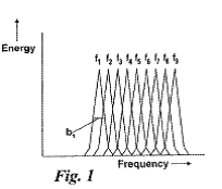
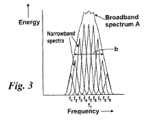 (from WO2010004333)
e.g. a parametric source with a non-linear medium to transform a high-frequency electric driving signal into a low frequency collimated beam.
frequency switching on transmit
Attention is drawn to the following places, which may be of interest for search:
Different forms of pulses | |
Investigating or analysing materials generating the ultrasonic waves with frequency characteristics, e.g. single frequency, chirps |
High frequency, i.e. above 20 MHz, ultrasound imaging should be classified here
G01S 15/8952 should be given for several Dirac peaks in the frequency spectrum
G01S 15/8954 should be given in case of a spread spectrum and of chirps. However, only when using ultrashort (and hence broadband) pulses
In case the two possibilities, G01S 15/8952 and G01S 15/8954, are relevant the main subgroup should be given, not both sub-groups
This place covers:
Acoustic short range imaging systems, in particular medical ultrasound imaging systems, using coded signals for pulse compression (coding by e.g. Golay codes, Barker codes or chirps), differentiating multiple transmit beams using coded signals.
In patent documents, the following abbreviations are often used:
PED | Pulse Elongation and Deconvolution |
This place covers:
Acoustic short range imaging systems, in particular medical ultrasound imaging systems, with an optical-acoustic transducer structure using an absorbed pump light pulse in the transducer probe to generate a sound pulse;
Systems comprising two acoustic arrays with circuitry between them in order to work after the manner of a lens; Interferometric detection of reflected ultrasound waves for imaging purposes.
Attention is drawn to the following places, which may be of interest for search:
Optoacoustic imaging, i.e. imaging of tissue using ultrasound waves generated in the tissue by a laser pulse | |
Investigating materials with probes using optoacoustic interaction with the material, e.g. laser radiation | |
Devices for manipulating acoustic surface waves | |
Sound-production using optical excitation per se, e.g. laser bundle |
This place covers:
Interferometric detection of reflected acoustic waves for imaging purposes using the acoustical modulation of a light beam
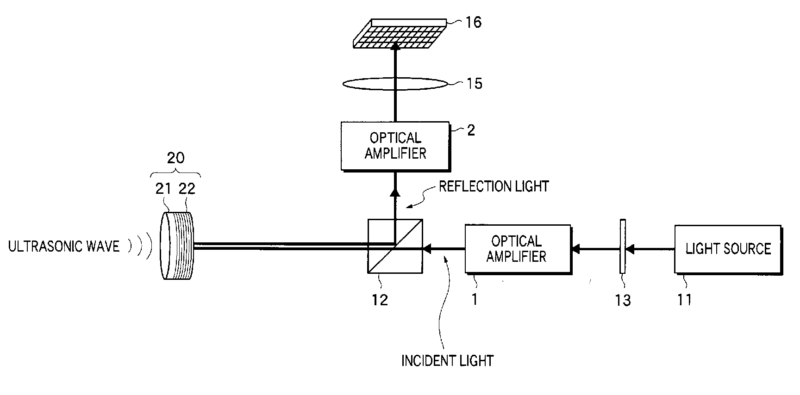
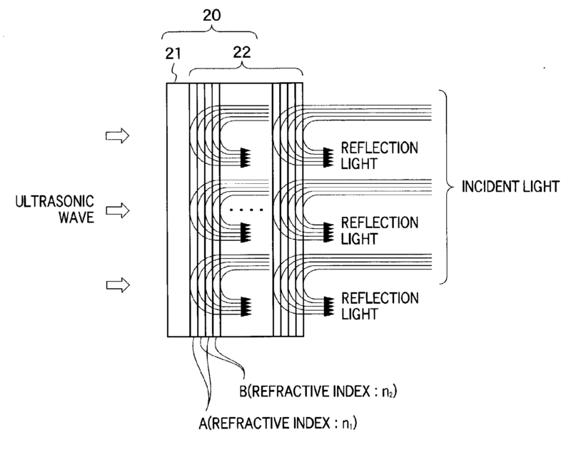 (from EP1298450, published 2003)
This place does not cover:
Control the position or direction of light beams using acousto-optical deflection devices | |
Control of amplitude or phase of light based on acousto-optical elements |
Attention is drawn to the following places, which may be of interest for search:
Measuring ultrasonic waves using mechanical fibre optic sensors | |
Investigating materials whereby incident light is modified using opto-acoustic detection |
This place covers:
example:
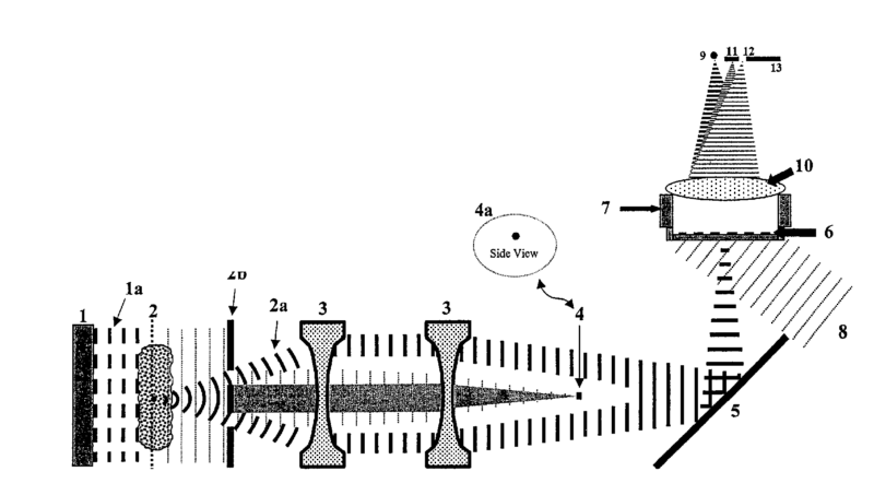
(from WO03032817)
Attention is drawn to the following places, which may be of interest for search:
Analysing solids using the imaging of the interior by acoustic holography | |
Holography per se | |
Acoustic holography per se |
This place covers:
Using e.g. Sokolov tubes for ultrasound detection (obsolete: technique from the 1980s)
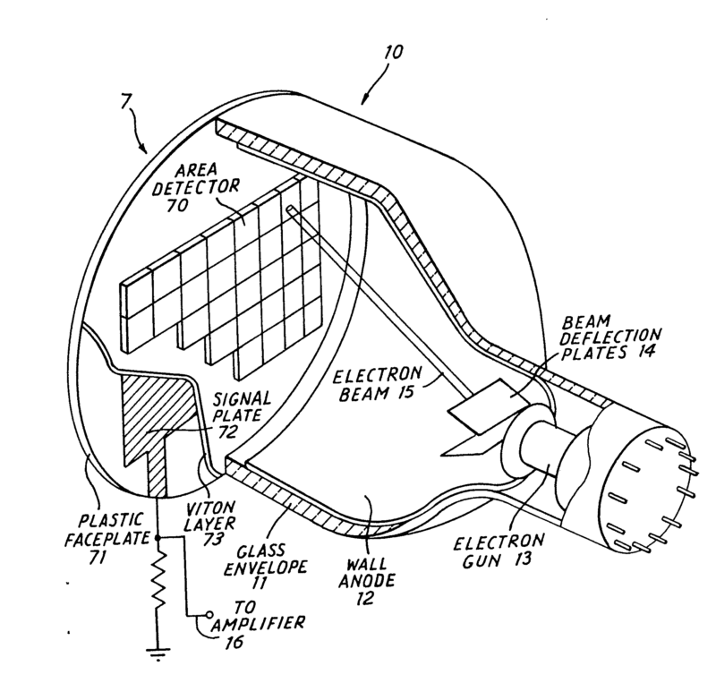 (from GB2066957, published 1981)
This place does not cover:
Tubes for acoustical image/electron beam converters |
This place covers:
Acoustic short range imaging systems, in particular medical ultrasound imaging systems, using special techniques on the already acquired set of acoustic data to (re)construct an image from these data.
Attention is drawn to the following places, which may be of interest for search:
Analysing materials by processing the detected response signal using | |
Statistical methods | |
Spectral analysis (e.g. FFT) | |
Auto- or cross-correlation techniques | |
Digital image processing per se |
This place covers:
- Acoustic short range imaging systems, in particular medical ultrasound imaging systems, using duplex imaging, i.e. colour coded flow velocity information extracted using Doppler signals overlaid as parametric information on B-mode images.
- General Doppler systems.
Attention is drawn to the following places, which may be of interest for search:
Systems relating to spectral Doppler only | |
For the principle underlying wall filters (i.e. G01S 15/8981) | |
Determining the velocity vector | |
Measuring blood flow for medical diagnosis | |
Diagnostic techniques involving Doppler signals | |
Blood flow in combination with B-scan for diagnosis | |
Measuring of volume flow using ultrasound | |
Measuring speed of fluids in general |
This place covers:
Acoustic short range imaging systems, in particular medical ultrasound imaging systems, wherein the ancillary equipment has a direct and important influence on the acoustic imaging itself.
Attention is drawn to the following places, which may be of interest for search:
Measuring for diagnostic purposes | |
Ultrasound lithotripsy | |
ICT specially adapted for handling or processing of medical images |
In this place, the following terms or expressions are used with the meaning indicated:
Ancillary equipment | supplementary or auxiliary devices, for supplementary sensing or monitoring during imaging, such as temperature sensors, cooling systems, tracking systems, docking units, ECG systems, high intensity focused ultrasound probes used for or during imaging, or combinations thereof |
In patent documents, the following abbreviations are often used:
ECG | Electrocardiogram |
PPG | photoplenthysmography, e.g. a pulse oximeter |
This place covers:
Acoustic short range imaging systems, in particular medical ultrasound imaging systems, using the acquisition of a three-dimensional set of data to produce via per se well-known rendering techniques a three-dimensional image.
Attention is drawn to the following places, which may be of interest for search:
Three-dimensional stereoscopic images | |
Diagnosis using ultrasound 3D | |
3D image rendering | |
Ray tracing per se | |
Volume rendering per se | |
3D modelling, e.g. data description of 3D objects | |
Manipulating 3D images |
In patent documents, the following abbreviations are often used:
3D | three-dimensional |
Attention is drawn to the following places, which may be of interest for search:
In this place, the following terms or expressions are used with the meaning indicated:
Spatial Compounding | Averaging of frames that view anatomy from different imaging angles. |
Attention is drawn to the following places, which may be of interest for search:
Constructional features of systems using the reflection or reradiation of acoustic waves, e.g. sonar systems | |
Methods or apparatus for generating or transmitting mechanical vibrations of infrasonic, sonic or ultrasonic frequency | |
Mountings or casings of devices in which sound is produced by vibrating a diaphragm or analogous element | |
Mounting transducers, provided with mechanical moving or orienting device |
Attention is drawn to the following places, which may be of interest for search:
Radar in the bumper area for anti-collision purposes of land vehicles | |
Bumpers with obstacle sensors of electric or electronic type |
This place covers:
This main group covers systems for detecting presence, distance, position, movement and velocity of objects in space using the reflection of propagating electromagnetic waves or re-radiation (G01S 17/74) of electromagnetic waves where the wavelength of the electromagnetic waves is shorter than the range of electromagnetic wavelengths including millimetric waves.
Disclosures of generic systems for detecting presence, distance, position, movement and velocity of objects in space using the reflection of propagating electromagnetic waves or re-radiation of electromagnetic waves where the range of wavelengths are not explicitly mentioned, go in G01S 13/00; but if these systems include features which are identifiable as relating to optical systems, then a class is also given in G01S 17/00.
Attention is drawn to the following places, which may be of interest for search:
Measuring linear dimensions, e.g. length, thickness, and distances between spaced objects | |
Measuring distances, levels, bearings; surveying; navigation | |
Photogrammetry or videogrammetry | |
Measuring light per se | |
Investigating materials by optical radiation, microwaves or acoustic waves | |
Measuring linear or angular speed, indicating presence, absence, or direction of movement | |
Detecting masses or objects by methods not involving reflection or reradiation of radio, acoustic, or other waves; prospecting | |
Optical systems | |
Control of position, course, altitude or attitude | |
Detecting the presence of objects for the purpose of counting them | |
Traffic control systems; anti-collision systems | |
Laser per se |
Details of disclosures of systems which conceptually form a technically important or technically non-trivial part of a disclosure should be classified in G01S 7/48, as well as the appropriate system group in G01S 17/00, especially if these details form a significant part of the disclosure, and do not concern well-known and widely retrievable subject-matter.
Systems for optically measuring the velocity of particles suspended in fluids by reflection are put in G01S 17/58
In this place, the following terms or expressions are used with the meaning indicated:
Triangulation | identifying an unknown location by calculating the length of one side of a triangle based on distance and angle measurements to known reference points |
Trilateration | identifying an unknown location by using the geometry of triangles and spheres. |
Multilateration | identifying an unknown location using a process similar to triangulation and trilateration using three or more known reference points. |
In patent documents, the following words/expressions are often used as synonyms:
- "Lidar", "Ladar" and "Laser Radar"
This place covers:
Systems where only the detection of the existence or not of a signal reflected from a target to the receiver is important.
Attention is drawn to the following places, which may be of interest for search:
Prospecting by optical means; detecting the presence of objects or masses by optical means, e.g. by interruption of beams, i.e. light barriers |
This place covers:
Systems where the position of the emitting system is determined relative to a reference frame, using active optical range finding. Systems where the position of a target is determined with respect to a measuring point, using signals reflected by the target, provided that these signals were not emitted by a single, well-defined source.
This place does not cover:
Indirect determination of position data | |
Active triangulation systems, i.e. using the transmission and reflection of electromagnetic waves other than radio waves |
Where a disclosure specifies alternative methods of measuring distance, for example, both time of flight of a transmitted and received optical pulse, as well as a time of flight measured with a transmitted and reflected continuous wave optical signal, and if these are described in detail, then the disclosure is classified in both G01S 17/10.
Attention is drawn to the following places, which may be of interest for search:
Interferometers per se | |
Optically measuring length, width or thickness |
Interferometers per se; G01B 9/00: optically measuring length, width or thickness by measuring distance to an object; G01B 11/026.
This place covers:
Other coordinates include Cartesian or polar spatial coordinates of target.
This place does not cover:
Indirect determination of position data |
Attention is drawn to the following places, which may be of interest for search:
Bearing and direction finders per se |
This place covers:
Techniques for determining position involving the use of indirect waves, e.g. waves travelling along multiple paths.
In this place, the following terms or expressions are used with the meaning indicated:
Active system | An active system uses a transmitter and a receiver. |
Passive system | A passive system listens without transmitting. |
This place covers:
Measuring the properties of the reflected signal in order to calculate the velocity of a moving target. The moving target may be a solid object or particles suspended in a moving fluid.
Attention is drawn to the following places, which may be of interest for search:
Teaching or practice apparatus for gun-arming or gun-laying using reflecting targets or active targets |
This place covers:
Optical imaging systems which are active, i.e. a dedicated illuminator/transmitter whether coherent or not is present, and the depth and/or range to objects within the illuminated space is measured
Attention is drawn to the following places, which may be of interest for search:
Optically measuring length, width or thickness | |
Surveying systems per se | |
Television/imaging systems not having range measurement per se |
Optically measuring length, width or thickness using tv-camera scanning; G01B 11/022: television/imaging systems not having range measurement per se; H04N: surveying systems per se; G01S 15/00.
This place covers:
Systems for generating a 3D image without scanning a light beam, e.g. time-of-flight cameras or flash LADAR.
Attention is drawn to the following places, which may be of interest for search:
Depth or shape recovery from laser ranging | |
Stereoscopic imaging in combination with an illumination source for illuminating objects | |
Stereoscopic imaging wherein the generated image signals comprise depth maps or disparity maps |
This place covers:
- Satellite radio beacon positioning systems including receivers and elements cooperating therewith.
- Determination of position, velocity or attitude using signals transmitted by such systems.
Relating to G01S 19/03, G01S 19/25, G01S 19/41, G01S 19/43 and G01S 19/45:
The distinction made between the use of subgroups of G01S 19/03 and subgroups with similar sounding names, such as G01S 19/25, G01S 19/41, G01S 19/43, G01S 19/45 is according to where the invention lies. Taking G01S 19/07 and G01S 19/41 an example: publications relating to differential GPS often mention both the reference station which creates the differential corrections and the act of correcting the position in the receiver. Usually, the inventive information present in a publication will relate either to the act of correction, or to reference station and method of sending the correction data to the receiver. Should the subject matter relate to carrying out correction, G01S 19/41 should be allocated; in the case of creating the differential data in the reference station or transferring it to the receiver, G01S 19/07 should be allocated. It is not uncommon for cooperating elements to provide all or some of the set of acquisition data, differential correction data, integrity data, ranging signals. Classification symbols should be given only to a document for those elements of the list which are part of the inventive disclosure of the document. Additional classification symbols may then be given to indicate the presence of the other information.
Relating to G01S 19/13 and G01S 19/39.
Subject matter related to the carrying out of processing not in the receiver itself, but at a remote station, should - in the absence of a dedicated subgroup in G01S 19/13 or G01S 19/42 - be allocated G01S 19/09.
Relating to G01S 19/14, G01S 19/35 and G01S 19/39
Subgroups – are "application-places for (GPS) receivers" insofar as they cover special characteristics of the (GPS) receivers, or specific constraints imposed on the receivers, so that they can adapt to the specific application. These subgroups do not cover the mere indication of the possible uses of a general GPS receiver.
The decision as to whether to classify in these groups will depend on the extent to which the invention relates to the core subject of these groups. Patent documents which deal with GPS merely as a "black box" to provide positioning information for use by the application would not normally be classified in these groups.
These subgroups are also intended as an aid in making search in other G01S 19/00 groups more efficient, as the application may suggest particular restrictions on the function of the receiver, e.g. a military application may imply a harsh electromagnetic environment and use of higher spec. components.
Should the matter in hand disclose constructional feature or software or hardware implementation issues, allocation of a G01S 19/35 code may be appropriate.
Matter relating to the determination of position, velocity and attitude should be classified in G01S 19/00, however, should matter be disclosed which would warrant classification and which relates to other parameters such as angular velocity, altitude, meteorological properties etc, such matter should be allocated to G01S 19/39.
In this place, the following terms or expressions are used with the meaning indicated:
Cooperating elements | designates additional elements or subsystems, including receivers of other users, which interact or communicate with the receiver to assist in acquisition or position determination. It does not refer to the ground control segments of the satellite systems. |
Time-stamped message | designates a message encoded with time of transmission for use in determining the signal travel time |
Relative Positioning | designates that position (angle + range) is calculated relative to another measured position. |
In patent documents, the following abbreviations are often used:
AGPS | Assisted (or aided) GPS |
DGPS | Differential GPS |
GLONASS | Global Orbiting Navigation Satellite System |
GPS | Global Positioning System |
IMU | Inertial Measurement Unit |
INS | Inertial Navigation System |
LAMBDA | Least-squares AMBiguity Decorrelation Adjustment |
This place does not cover:
Services making use of the location of users or terminals, i.e. position related information. |
Where the matter refers to a transmitter having more general application than merely GPS related, classification in G01S 1/00 should also be considered.
Attention is drawn to the following places, which may be of interest for search:
Beacons transmitting signals having a characteristic or characteristics capable of being detected by non-directional receivers and definition direction, positions, or position lines |
This place does not cover:
Receivers present in cooperating elements, in so far as they would not be susceptible of more general application, should be classified in the relevant subclass of: |
Examples of places where the subject matter of this place is covered when specially adapted, used for a particular purpose, or incorporated in a larger system:
Fire Fighting | |
Apparatus for physical training, sports | |
Vehicle fittings for preventing or indicating unauthorised use or theft of vehicles | |
Surveying | |
Navigation | |
Electronic time-pieces for aspects of time-setting or synchronization | |
Alarms responsive to a single specified undesired or abnormal operating condition | |
Alarm systems in which the location of the alarm condition is signalled to a central station, e.g. fire or police telegraphic systems | |
Traffic control systems for road vehicles | |
Locating users or terminals for network management purposes |
Attention is drawn to the following places, which may be of interest for search:
Spoofers, jammers etc. | |
Interference related aspects in spread spectrum receivers |
Multipath detection and mitigation is often tightly bound to the signal acquisition. Where the subject matter related to signal acquisition is more generally applicable, classification in G01S 19/30 may also be desirable.
G01S 19/22 and G01S 19/428 both relate to multipath issues. Matter in G01S 19/22 relates principally to identification and mitigation of multipath effects. G01S 19/428 contains matter in which the multipath signals are deliberately taken into account to calculate position.
Attention is drawn to the following places, which may be of interest for search:
Automatic control of frequency or phase; synchronisation |
The decision to classify in G01S 19/23 or G01S 19/235 relates to the interpretation of the term "calibration". In GPS, it is foreseen that the oscillator used for signal acquisition and tracking operates well - any procedure to bring to oscillator into alignment with its correct operating frequency is considered calibration. A receiver, however, is not expected to maintain exact time, as this is a by-product of position calculation. Thus, time is not calibrated.
Attention is drawn to the following places, which may be of interest for search:
Spread spectrum techniques in general using direct sequence modulation (DSM) | |
Synchronisation aspects of direct sequence spread spectrum modulation |
Reduced energy consumption due to an improved acquisition paradigm or apparatus, e.g. reduced time to first fix due to acquisition aiding. Improvement in acquisition etc which necessarily result in improved power consumption should not be classified here.
Attention is drawn to the following places, which may be of interest for search:
Printed circuits; casing or constructional details of electric apparatus |
This place covers:
Constructional details relating to the front end; also positioning of the front end, if separated from the processing navigation processor.
Attention is drawn to the following places, which may be of interest for search:
Aerials |
G01S 19/30 takes precedence. Should the hardware details be so specific that they have no application outside of G01S 19/30, then there is no need to classify these aspects in G01S 19/37
Although matter relating to the determination of position, velocity and attitude should only by classified in G01S 19/00; however, should it be necessary to indicate that another parameter is being measured, e.g. angular velocity, altitude, meteorological properties, such matter should be allocated G01S 19/39.
This place covers:
Position determination where multipath or indirect path signals are deliberately taken into account to calculate position.
This place does not cover:
Identification and mitigation of multipath effects; these are classified in: |
This place covers:
Positioning solutions where measurements are combined to arrive as a position involving inertial measurement.
This place does not cover:
Progressing forward in time by integration of inertial measurements a position solution derived from GPS signals, i.e. this subgroup does not cover the combination of positions with measurements. Such positioning algorithms are found in: |
This place covers:
By a combination of GPS and another positioning technique, e.g. from Wi-Fi® signals, or by switching between the two techniques. Switching between routines is often done when the electromagnetic environment, energy requirements, state of movement in which the receiver finds itself is more or less suitable for position determination by GPS.
G01S 5/01 should be allocated where the electromagnetic environment, e.g. multipath or suggesting an indoor rather than an outdoor environment, or any other aspect which would determine the choice of combination/switch of positioning technique, is determined.