CPC Definition - Subclass F16H
This place covers:
Gearings for conveying rotary motion:
- Toothed gearings;
- Friction gearings, e.g. gearings using endless flexible members;
- Fluid gearings;
- Change speed or reversing gearings;
- Differential gearings;
- Using intermittently-driving members;
- Gearings not limited to rotary motion;
- Mechanical gearings using levers, links or cams; or
- Using intermittently-driving members.
Combination of gearings.
General details of gearings.
Control of gearings.
Subclass F16H for gearings is a function-oriented place. Gearings or transmissions comprising general applicable inventions or intended for different applications are classified in this subclass. Specially adapted gearings for a particular purpose are classified in the related subclass for the application. Some examples where these gearings will be classified when specially adapted or for a particular purpose could be found in the following list of references.
Examples of places where the subject matter of this place is covered when specially adapted, used for a particular purpose, or incorporated in a larger system:
Gearings in harvesters or mowers | |
Gearings in balers | |
Gearings in surgical tools | |
Gearings for toys | |
Toothed-wheel gearing for metal-rolling mills | |
Varying the speed ratio of driving or feeding mechanisms of machine tools | |
Gearings for portable rotary tools | |
Gearings for manipulators | |
Gearings in torque-transmitting axles | |
Conjoint control of drive units for vehicles | |
Transmissions for railway locomotives | |
Vehicle steering gears | |
Cycle transmissions | |
Marine propulsion | |
Transmissions for marine propulsion | |
Marine steering gears | |
Gearings for control surfaces in airplane and helicopters | |
Gearings for aircraft propellers or rotors | |
Gearings in dredging or soil shifting machines | |
Gearings in gas turbine plants | |
Transmission of mechanical power for wind motors | |
Gearings associated with fluid-actuated devices | |
Gearing used in indicating or recording apparatus in connection with measuring devices | |
Driving arrangements for tuning resonant circuits | |
Driving mechanisms for apparatus for transmission of coded digital information |
Attention is drawn to the following places, which may be of interest for search:
Arrangement of transmissions in vehicles | |
Fluid actuators | |
Couplings for transmitting rotation; Clutches |
The use of the available Indexing Codes in this subclass is mandatory and should be assigned for additional information to facilitate searching. The Indexing Codes under F16H 2700/00 are no longer used for classifying new documents.
In this place, the following terms or expressions are used with the meaning indicated:
gearing | mechanical, hydraulic, electric or other means for transmitting mechanical motion or force |
gearbox | housing of the gearing |
toothed gearing | includes worm gearing and other gearing involving at least one wheel or sector provided with teeth or the equivalent, except gearing with chains or toothed belts, which is treated as friction gearing |
conveying motion | includes transmitting energy, and means that the applied and resultant motions are of the same kind, though they may differ in, e.g. speed, direction or extent |
rotary motion | implies that the motion may continue indefinitely |
oscillating motion | moving about an axis to an extent which is limited by the construction of the gearing and which may exceed one revolution, the movement being alternately forwards and backwards during continued operation of the gearing |
reciprocating motion | moving substantially in a straight line, the movement being alternately forwards and backwards during continued operation of the gearing |
reversing or reversal | applied movement in one direction may produce a resultant movement in either of two opposed directions at will. Note: When reversing reciprocating motion, input rotary motion (which is defined as indefinitely continuous rotary motion) would cause an automatic reversal of the reciprocating motion. If the input rotational direction is changed in order to cause reversal of the reciprocating motion, the input motion is an oscillating motion (which is defined as alternately forward and backward rotary motion) |
central gears | includes any gears whose axis is the main axis of the gearing, e.g. sun or ring gear |
Ravigneaux set | a planetary gear set with at least three central gears, and conveying rotary motion between axially-spaced orbital gears. It comprises a long orbital gear consisting of two axially spaced orbital gears which are fixedly connected to each other. It comprises a further orbital gear which meshes with one of the orbital gears of the long orbital gear to form a pair of intermeshing orbital gears. All orbital gears are mounted on a common planet carrier and are considered as a single set of orbital gears. |
creeping | the vehicle has come to a stop, the engine is at idle (i.e., there is no request by the operator for a higher engine speed/torque), but due to the rotation of various transmission components, the vehicle starts to move, and the vehicle operator has some control over movement with a brake |
inching | the vehicle operator has some control, besides using a brake, over moving the vehicle by small degrees |
This place covers:
Gearing with fixed gear ratio using only gears with teeth.
This place does not cover:
Toothed gearing for conveying rotary motion with variable gear ratio of for reversing rotary motion |
Attention is drawn to the following places, which may be of interest for search:
Combinations of mechanical gearings | |
Gears associated with electric machines |
This place covers:
Toothed gearings for conveying rotary motion in which torque may be transmitted from the input to the output in only one input rotation direction, e.g. a clockwise input rotation is possible whereas a counter-clockwise input rotation is blocked.
Illustrative examples of subject matter classified in this place:
1a.

Figure 1a illustrates an example in which clockwise rotation is possible.
1b.

Figure 1b illustrates an example in which counter clockwise rotation is blocked.
2a.

2b.

Figures 2a and 2b illustrate an example in which rotation is allowed in only one direction.
Attention is drawn to the following places, which may be of interest for search:
Gearings or mechanisms preventing back-driving | |
Mechanically driven watches or clocks including devices allowing the motion of a rotatable part in only one direction |
This place covers:
Illustrative examples of subject matter classified in this place:
1a.

1b.

Figures 1a and 1b illustrate a worm drive shaft (a) and driven shaft (d) which may assume variable positions to one another, i.e. worm drive shaft (a) may pivot around driven shaft (d).
2.

Figure 2 illustrates a drive shaft (left outermost gear) and a driven shaft (right outermost gear) may assume variable positions to one another, i.e. gear train (252B) may pivot with respect to gear train (252A).
Attention is drawn to the following places, which may be of interest for search:
Angle drives for machine tools | |
Yielding couplings, i.e. with means permitting movement between the connected parts during the drive, e.g. universal joints |
This place covers:
Non-orbital toothed gearing wherein no more than a total of two intermeshing members are used to convey rotary motion.
Attention is drawn to the following places, which may be of interest for search:
Toothed gearings for conveying rotary motion, with fixed gear ratio, without gears having orbital motion, involving more than two intermeshing members |
This place covers:
Toothed gearings for conveying rotary motion, with fixed gear ratio, without gears having orbital motion, involving only two intermeshing members, with parallel axes.
Illustrative examples of subject matter classified in this place:
1.

Figure 1 illustrates a gearing having two parallel axes and involving only two intermeshing members (1) and (2). The latter are formed as spur gears.
2.

Figure 2 illustrates a gearing having two parallel axes and involving only two intermeshing members (1) and (2). The latter are formed as face gears.
This place covers:
Toothed gearings for conveying rotary motion, with fixed gear ratio, without gears having orbital motion, involving only two intermeshing members, with parallel axes, the members having helical, herringbone or like teeth.
Illustrative examples of subject matter classified in this place:
1.

Figure 1 illustrates a helical gearing having two parallel axes and involving only two intermeshing members (a) and (b). The latter having helical teeth.
2.

Figure 2 illustrates a double helical gearing having two parallel axes and involving only two intermeshing members (3) and (4). Each of the latter having two rows (1) and (2) of oppositely inclined helical teeth.
3.

Figure 3 illustrates a herringbone gearing having parallel axes (I) and (II) and involving only two intermeshing members (a1) and (a2). The latter having herringbone teeth.
Attention is drawn to the following places, which may be of interest for search:
Toothed gearings for conveying rotary motion, with fixed gear ratio, without gears having orbital motion, involving more than two intermeshing members, characterised by the driving or driven member being composed of two or more gear wheels |
This place covers:
Toothed gearings for conveying rotary motion, with fixed gear ratio, without gears having orbital motion, involving only two intermeshing members, with parallel axes, one of the members being internally toothed.
Illustrative example of subject matter classified in this place:

The Figure illustrates a gearing having two parallel axes and involving only two intermeshing members (1) and (2). Member (1) is internally toothed.
Attention is drawn to the following places, which may be of interest for search:
Turntables, i.e. structure rotatable about 360°, e.g. slew drives |
This place covers:
Toothed gearings for conveying rotary motion, with fixed gear ratio, without gears having orbital motion, involving only two intermeshing members, with non-parallel axes.
Illustrative example of subject matter classified in this place:
1a.

Figure 1a illustrates a crown gearing involving only two intermeshing members (1) and (2). Axes (3) and (4) are intersecting and non-parallel. Gears (1) and (2) are not conical.
1b.

This place covers:
Toothed gearings for conveying rotary motion, with fixed gear ratio, without gears having orbital motion, involving only two intermeshing members, with non-parallel axes, comprising spiral gears.
Illustrative examples of subject matter classified in this place:
1.

Figure 1 illustrates a gearing involving only two intermeshing members (4) and (8), with non-parallel axes (2) and (3). Intermeshing member (4) has spiral teeth. The gearing does not have conical gears.
2.

Figure 2 illustrates a gearing involving only two intermeshing members (20) and (52), with non-parallel and intersecting axes (F) and (P). Intermeshing members (20) and (52) have spiral teeth. The gearing does not have conical gears.
3.

Figure 3 illustrates a gearing involving only two intermeshing members (1) and (2), with non-parallel and non-intersecting axes. Intermeshing members (1) and (2) have spiral teeth. The gearing does not have conical gears.
Attention is drawn to the following places, which may be of interest for search:
Comprising conical gears only, with offset axes, e.g. hypoïd gearings |
This place covers:
Toothed gearings for conveying rotary motion, with fixed gear ratio, without gears having orbital motion, involving only two intermeshing members, with non-parallel axes, comprising conical gears only.
Illustrative example of subject matter classified in this place:

The Figure illustrates a bevel gearing involving only two intermeshing members, i.e. bevel gears (2) and (4). The axes thereof are non-parallel.
Attention is drawn to the following places, which may be of interest for search:
Turntables, i.e. structure rotatable about 360°, e.g. slew drives |
This place covers:
Toothed gearings for conveying rotary motion, with fixed gear ratio, without gears having orbital motion, involving only two intermeshing members, with non-parallel axes, comprising conical gears only, with offset axes, e.g. hypoïd gearings.
Illustrative example of subject matter classified in this place:

The Figure illustrates a hypoïd gearing involving only two intermeshing members, i.e. conical gears (12) and (14). Axes (Og) and (Op) are offset by a distance (E), i.e. they do not intersect.
This place covers:
Toothed gearings for conveying rotary motion, with fixed gear ratio, without gears having orbital motion, involving only two intermeshing members, with non-parallel axes, comprising worm and worm-wheel.
Illustrative example of subject matter classified in this place:

The Figure illustrates a worm gearing involving only two intermeshing members, i.e. worm (2) and worm-wheel (5).
Attention is drawn to the following places, which may be of interest for search:
Special devices for taking up backlash for worms and worm gears | |
Support of worm gear shafts | |
Worm gears associated with electric machines |
This place covers:
Toothed gearings for conveying rotary motion, with fixed gear ratio, without gears having orbital motion, involving only two intermeshing members, with non-parallel axes, comprising worm and worm-wheel, with balls between the co-operating parts.
Illustrative example of subject matter classified in this place:

The Figure illustrates a worm gearing involving only two intermeshing members, i.e. worm (4) and worm-wheel (8), with balls (5) between co-operating worm (4) and worm-wheel (8).
This place covers:
Toothed gearings for conveying rotary motion, with fixed gear ratio, without gears having orbital motion, involving only two intermeshing members, with non-parallel axes, with members rotating around axes on the worm or worm-wheel.
Illustrative example of subject matter classified in this place:
1a.

1b.

Figures 1a and 1b illustrate a worm gearing involving only two intermeshing members, i.e. worm (12) and worm-wheel (10). Additionally, the worm gearing includes members, i.e. rollers (22), each rotating around an axis (24) on worm-wheel (10), which is perpendicular to axis (18) of worm wheel (10).
This place covers:
Toothed gearings for conveying rotary motion, with fixed gear ratio, without gears having orbital motion, involving only two intermeshing members, with non-parallel axes, the members having helical, herringbone or like teeth.
This place does not cover:
Toothed gearings for conveying rotary motion, with fixed gear ratio, without gears having orbital motion, involving only two intermeshing members, with non-parallel axes, comprising conical gears only |
This place covers:
Non-orbital toothed gearing wherein the total number of intermeshing members used to convey rotary motion is greater than two intermeshing members.
Illustrative example of subject matter classified in this place:

The Figure illustrates a reduction gearing, with a fixed gear ratio, involving more than two intermeshing members, i.e. gears (2), (3), (4) and (5).
Attention is drawn to the following places, which may be of interest for search:
Toothed gearings for conveying rotary motion, with fixed gear ratio, without gears having orbital motion, involving only two intermeshing members | |
Combinations of toothed gearings only, not provided for in groups F16H 1/00 - F16H 35/00, for conveying rotary motion with constant gear ratio |
This place covers:
Toothed gearings for conveying rotary motion, with fixed gear ratio, without gears having orbital motion, involving more than two intermeshing members, with non-parallel axes.
Illustrative examples of subject matter classified in this place:
1.

Figure 1 illustrates a gearing with a fixed gear ratio involving four intermeshing members, i.e. spur gears (20) and (22) and hypoïd gears (30) and (31). The axis of gear (31) is not parallel with the axes of gears (20), (22) and (30).
2.

Figure 2 illustrates a gearing with a fixed gear ratio involving six intermeshing bevel gears. The gearing has four non-parallel axes of rotation.
3.

Figure 3 illustrates a gearing with a fixed gear ratio involving four intermeshing members, i.e. bevel gears (4) and (300) and spur gears (7) and (8). The axis of gear (300) is not parallel with the axes of gears (4), (7) and (8).
4.

Figure 4 illustrates a gearing with a fixed gear ratio involving four intermeshing members, i.e. worm (2), worm wheel (3), and spur gears (4) and (5). The axis of worm (2) is not parallel with the axes of gears (3), (4) and (5).
This place does not cover:
Toothed gearings for conveying rotary motion, with fixed gear ratio, without gears having orbital motion, involving more than two intermeshing members, with a plurality of driving or driven shafts or with arrangements for dividing torque between two or more intermediate shafts |
This place covers:
Toothed gearings for conveying rotary motion, with fixed gear ratio, without gears having orbital motion, involving more than two intermeshing members, characterised by the driving or driven member being composed of two or more gear wheels.
Illustrative example of subject matter classified in this place:

The Figure illustrates a toothed gearing involving ten intermeshing members, i.e., gear pairs (11') and (13'), (12') and (14'), (15') and (16'), (17') and (19'), and (10') and (18'). The driving member, i.e. input shaft (1'), is composed of two gear wheels (11') and (12'). The driven member, i.e. output shaft (4'), is composed of two gear wheels (19') and (10').
Attention is drawn to the following places, which may be of interest for search:
Toothed gearings with gears having herringbone teeth, for conveying rotary motion, with fixed gear ratio, without gears having orbital motion, involving only two intermeshing members, with parallel axes |
This place covers:
Toothed gearings for conveying rotary motion, with fixed gear ratio, without gears having orbital motion, involving more than two intermeshing members, with a plurality of driving or driven shafts or with arrangements for dividing torque between two or more intermediate shafts.
Illustrative examples of subject matter classified in this place:
1.

Figure 1 illustrates a toothed gearing with a fixed gear ratio and fourteen intermeshing gears. The gearing has one driven shaft (27) and two driving shafts (13) and (13').
2.

Figure 2 illustrates a toothed gearing with a fixed gear ratio and four intermeshing gears. Torque from the driving shaft is divided between two intermediate shafts and summed at the driven shaft.
Attention is drawn to the following places, which may be of interest for search:
Toothed gearings for conveying rotary motion, with fixed gear ratio, with gears having orbital motion |
This place covers:
Toothed gearings for conveying rotary motion, with fixed gear ratio, without non-parallel axes, without gears having orbital motion, involving more than two intermeshing members, with a plurality of driving or driven shafts or with arrangements for dividing torque between two or more intermediate shafts, with non-parallel axes.
Illustrative examples of subject matter classified in this place:
1.

Figure 1 illustrates a toothed gearing with a fixed gear ratio and intermeshing gears (1), (2), (3), (4), (1'), (2'), (3'), and (4'). The gearing includes a driving shaft 6 and two driven shafts (5) and (5'). Torque flows from driving shaft (6) via bevel gears (1) and (2), internal gear (3) and external gear (4) to driven shaft (5); and from driving shaft (6) via bevel gears (1') and (2'), internal gear (3') and external gear (4') to driven shaft (5').
2.

Figure 2 illustrates a toothed gearing with a fixed gear ratio and eight intermeshing gears. Torque from driving shaft (1) is divided between intermediate shafts (12) and (13) and summed at driven shaft (2).
This place covers:
Toothed gearings for conveying rotary motion, with fixed gear ratio, without gears having orbital motion, involving more than two intermeshing members, with a plurality of driving or driven shafts or with arrangements for dividing torque between two or more intermediate shafts, with two or more worm and worm-wheel gearings.
Illustrative examples of subject matter classified in this place:
1.

Figure 1 illustrates a toothed gearing with a fixed gear ratio and four intermeshing gears. The gearing includes a driven shaft (1) and three driving worm shafts (2), (3) and (7).
2.

Figure 2 illustrates a toothed gearing with a fixed gear ratio and seven intermeshing gears. Torque from the driving shaft, i.e. worm shaft (1), is divided between intermediate worm shafts (7) and (6) and summed at driven shaft (2).
This place covers:
Toothed gearings for conveying rotary motion, with fixed gear ratio, without gears having orbital motion, involving more than two intermeshing members, with a plurality of driving or driven shafts or with arrangements for dividing torque between two or more intermediate shafts, comprising two or more gearwheels in mesh with the same internally toothed wheel.
1.

Figure 1 illustrates a toothed gearing with a fixed gear ratio and six intermeshing gears. The gearing includes two driving shafts (5) and a driven shaft (8). Both gearwheels (3) are in mesh with the same internally toothed wheel (2a).
2.

Figure 2 illustrates a toothed gearing with a fixed gear ratio and four intermeshing gears. Torque from driving shaft (16) is divided between intermediate shafts (36) and (37) and summed at internally toothed gear (21), which forms the driven shaft. Gearwheels (26) and (31) mesh with the same internally toothed wheel (21).
3.

Figure 3 illustrates a toothed gearing with a fixed gear ratio and four intermeshing gears. Torque from driving shaft (121) is divided between intermediate shafts (140) and summed at internally toothed gear (131), which forms the driven shaft. Gearwheels (132) mesh with the same internally toothed wheel (131).
Attention is drawn to the following places, which may be of interest for search:
Toothed gearings for conveying rotary motion with gears having orbital motion |
This place covers:
Toothed gearings for conveying rotary motion, with fixed gear ratio, without gears having orbital motion, involving gears essentially having intermeshing elements other than involute or cycloidal teeth.
Illustrative example of subject matter classified in this place:
1a.
1b.

Figures 1a and 1b illustrate a gearing with a fixed gear ratio and without gears having orbital motion. Rollers (5) of gear (2) mesh with semi-circular grooves (4) of gear (1). In other words, the gearing includes intermeshing elements which are neither involute nor cycloidal teeth.
This place does not cover:
Toothed gearings for conveying rotary motion, with fixed gear ratio, without gears having orbital motion, involving only two intermeshing members, with non-parallel axes, comprising worm and worm-wheel |
This place covers:
Special means compensating for misalignment of axes of toothed gearings for conveying rotary motion, with fixed gear ratio, and without gears having orbital motion.
Illustrative example of subject matter classified in this place:

The Figure illustrates a toothed gearing comprising a pair of spur gears (6) and (10), driving shaft (6), and driven shaft (8). The gearing includes a spherical bearing formed on the drive shaft (8) in order to compensate for the misalignment of the axes associated with shafts (6) and (8), respectively.
Attention is drawn to the following places, which may be of interest for search:
Special means compensating for misalignment of axes of toothed gearings, with fixed gear ratio, comprising gears having orbital motion | |
Support of worm gear shafts in the gearbox |
This place covers:
Toothed gearings for conveying rotary motion, with fixed gear ratio, with gears having orbital motion.
Illustrative example of subject matter classified in this place:

The Figure illustrates an orbital or planetary gearing comprising sun gear (4), orbital or planet gears (5), ring or internal gear (6) and planet carrier (7). Input shaft (1) is connected to sun gear (4), output shaft (2) is connected to planet carrier (7), and ring gear (6) is fixed to housing (3). Planet gears (5) rotate around their own axis. In addition, due to rotation of the planet carrier (7), planet gears (5) also orbit relative to and around rotating sun gear (4), i.e. they have orbital motion.
Attention is drawn to the following places, which may be of interest for search:
Toothed gearings for conveying rotary motion, with fixed gear ratio, without gears having orbital motion, involving more than two intermeshing members, with arrangements for dividing torque between two or more intermediate shafts | |
Toothed gearings for conveying rotary motion, with fixed gear ratio, without gears having orbital motion, involving more than two intermeshing members, with arrangements for dividing torque between two or more intermediate shafts, comprising two or more gearwheels in mesh with the same internally toothed wheel | |
Differential gearing comprising bevel gears | |
Differential gearing comprising orbital spur gears | |
Transmission arrangements in gas turbine plants, or between the gas-turbine plant and the power user | |
Transmission of mechanical power in wind motors | |
Transmission of power in motors, machines or engines covered by subclasses F03B, F03D and F03G, e.g. in wind motors, by toothed gearing of the epicyclic, planetary or differential type |
In patent documents, the following words/expressions are often used as synonyms:
- "Planetary transmission" and "epicyclic transmission"
- "Gearing", "gear train" or "gear set"
This place covers:
Toothed gearings for conveying rotary motion, with fixed gear ratio, with gears having orbital motion, with means for equalising the distribution of load on the planet gears.
Attention is drawn to the following places, which may be of interest for search:
Toothed gearings for conveying rotary motion, with fixed gear ratio, with gears having orbital motion and with special means compensating for misalignment of axes, e.g. for equalising distribution of load on the face width of the teeth |
This place covers:
Toothed gearings for conveying rotary motion, with fixed gear ratio, with gears having orbital motion, with means for equalising the distribution of load on the planet-gears, by allowing limited movement of the ring gear relative to the casing or shaft.
Illustrative examples of subject matter classified in this place:
1.

Figure 1 illustrates a planetary gearing with a ring gear (2) connected to casing (5) via an elastically deformable wave element (16). The latter allowing limited movement of ring gear (2) relative to casing (5).
2.

Figure 2 illustrates a planetary gearing with a ring gear (3) connected to casing (7) via pins (5) and roller elements (6a) and (6b), thereby allowing limited movement of ring gear (3) relative to casing (7).
This place covers:
Toothed gearings for conveying rotary motion, with fixed gear ratio, with gears having orbital motion, with means for equalising the distribution of load on the planet-gears, by allowing limited movement of the planet carrier, e.g. relative to its shaft.
Illustrative example of subject matter classified in this place:

The Figure illustrates a planetary gearing with planet carrier (13) connected to output shaft (17) by double-tooth clutch (15) which is axially biased by spring (18). This connection allows a limited axial movement of planet carrier (13) relative to output shaft (17).
This place covers:
Toothed gearings for conveying rotary motion, with fixed gear ratio, with gears having orbital motion, with means for equalising the distribution of load on the planet-gears, by allowing limited movement of the planet gears relative to the planet carrier or by using free floating planet gears.
Illustrative examples of subject matter classified in this place:
1.

Figure 1 illustrates a planet gear (36) is rotatably mounted to planet carrier (38) via a planet bearing (63), a sleeve (56) and a flex-pin (40). Flex-pin (40) allows limited movement of planet gear (36) relative to planet carrier (38).
2a.

2b.

Figures 2a and 2b illustrates an example in which planet gears (6) are each rotatably mounted to planet carrier (3) by planet pins (12). Planet pins (12) may freely float within slits (11) in planet carrier (3).
This place covers:
Toothed gearings for conveying rotary motion, with fixed gear ratio, with gears having orbital motion, with means for equalising the distribution of load on the planet-gears, by allowing limited movement of the sun gear.
Illustrative example of subject matter classified in this place:

The Figure illustrates a planetary gearing including sun gear (9) connected to casing (10) via an elastically deformable wave element (24). The latter allowing limited movement of sun gear (9) relative to casing (10).
This place covers:
Toothed gearings for conveying rotary motion, with fixed gear ratio, with gears having orbital motion, involving conical gears.
Illustrative example of subject matter classified in this place:

The Figure illustrates a reduction gearing (40) including input shaft (31), output shaft (36), non-rotating housing (24) and bevel planet gear (42), i.e. a conical gear, having orbital motion.
Attention is drawn to the following places, which may be of interest for search:
Toothed gearings for conveying rotary motion, with fixed gear ratio, without gears having orbital motion, involving more than two intermeshing members, with arrangements for dividing torque between two or more intermediate shafts, with non-parallel axes, e.g. with bevel gears | |
Differential gearing with gears having orbital motion and comprising bevel gears |
This place covers:
Toothed gearings for conveying rotary motion, with fixed gear ratio, with gears having orbital motion, arrangements for adjusting or for taking-up backlash.
Illustrative example of subject matter classified in this place:

The Figure illustrates a planetary gearing including ring gear (5) having two parts (5') and (5''), which are rotated against each other to reduce the backlash between the teeth of the planet gears (3) and the teeth of the ring gear (5).
Attention is drawn to the following places, which may be of interest for search:
Special devices for taking up backlash for toothed bevel gears | |
Arrangements for adjusting or for taking-up backlash not provided for elsewhere |
This place covers:
Planetary gearing having a fixed gear ratio and including three central gears which are all engaged with the same planet gear, and the planet gear is mounted on an idling carrier.
Illustrative example of subject matter classified in this place:

The Figure illustrates a planetary gearing with a fixed gear ratio and including three central gears, i.e. sun gear (2) and two ring gears (3) and (4), which are all engaged by a common orbital gear (6) mounted on carrier (5). Carrier (5) is not connected to any shaft and therefore idles. In other words, carrier (5) constitutes an "idling carrier".
Attention is drawn to the following places, which may be of interest for search:
Toothed gearings for conveying rotary motion, with fixed gear ratio, with gears having orbital motion, comprising two axially spaced central gears, i.e. ring or sun gear, engaged by at least one common orbital gear wherein one of the central gears is forming the output |
This place covers:
Planetary gearing having a fixed gear ratio and including at least two axially spaced central gears which are both engaged with the same planet gear, and one of the at least two axially spaced central gears is the output for the gearing.
Illustrative example of subject matter classified in this place:

The Figure illustrates a planetary gearing with a fixed gear ratio and including two axially spaced central gears, i.e. ring gears (5) and (7), which are both engaged by a common orbital gear (3) and (3'). Ring gear (7) forms the output of the gearing.
Attention is drawn to the following places, which may be of interest for search:
Toothed gearings for conveying rotary motion, with fixed gear ratio, with gears having orbital motion, comprising three central gears, i.e. ring or sun gear, engaged by at least one common orbital gear mounted on an idling carrier |
Planetary gearings falling within the scope of both F16H 2001/2872 and F16H 2001/2881, are classified in F16H 2001/2872 only.
This place covers:
Toothed gearings for conveying rotary motion, with fixed gear ratio, with gears having orbital motion, comprising two or more coaxial and identical sets of orbital gears, e.g. for distributing torque between the coaxial sets.
Illustrative example of subject matter classified in this place:

The Figure illustrates a planetary gearing with a fixed gear ratio and comprising a first set of planet gears (25) and a second set of planet gears (25'). The two sets of planet gears (25) and (25') are coaxial and identical.
This place covers:
Toothed gearings for conveying rotary motion, with fixed gear ratio, with gears having orbital motion, in which an orbital gear is a worm; or in which the orbital gear has helical teeth and an axis crossing the main axis of the gearing.
This area also includes gearing in which the orbital gear has helical teeth and where the axis of the orbital gear is set at an angle relative to the main axis.
Illustrative examples of subject matter classified in this place:
1a.

1b.

Figures 1a and 1b illustrate a planetary gearing, with a fixed gear ratio, comprising four orbital gears (9), each of which is a worm.
2a.

2b.

Figures 2a and 2b illustrate a planetary gearing comprising three orbital gears (16), each of which has helical teeth and an axis (17) set at an angle α relative to the main axis (18).
This place covers:
Toothed gearings for conveying rotary motion, with fixed gear ratio, with gears having orbital motion, in which the central axis of the gearing lies inside the periphery of an orbital gear, e.g. eccentric gearing or cycloidal gearing.
Attention is drawn to the following places, which may be of interest for search:
Gearings comprising cams for conveying rotary motion, with intermediate members guided along tracks on both rotary members | |
Wave gearings | |
Cycloidal or planetary mechanisms for adjustable back-rest in which the central axis of the gearing lies inside the periphery of an orbital gear, e.g. one gear without sun gear |
This place covers:
Illustrative examples of subject matter classified in this place:
1.

Figure 1 illustrates a planetary gear set in which orbital gears (9) and (9') are nutating.
2.

Figure 2 illustrates a planetary gear set in which orbital gears (9) and (11) are nutating.
This place covers:
Illustrative examples of subject matter classified in this place:
1.

Figure 1 illustrates a planetary gear set including an input crank (b), an output (f), an eccentric orbital gear (d) and a flexible coupling (g).
2.

Figure 2 illustrates a gearing including a planetary gear set having carrier (5) with mounted orbital gears (11) interacting with sun gear (3). The gearing further includes universal joints (28), (33) attached to the output of the planetary gear set.
This place covers:
Illustrative example of subject matter classified in this place:
1a.

1b.

Figures 1a and 1b illustrate a planetary gear set (1) includes an eccentric crankshaft (10) driven by input shaft (8), eccentric orbital gears (14a), (16a) driven by eccentric crankshaft (10) and output shaft (4).
This place covers:
Illustrative example of subject matter classified in this place:

The Figure illustrates a planetary gear set including eccentric input shaft (F), axially spaced and rigidly interconnected eccentric orbital gears (B), (D) and output shaft (C).
This place covers:
Orbital gearing in which the orbital movement of the orbital gears is transferred eccentrically around the main axis of the gearing by carrier pins interacting with circular holes, e.g. cycloid gearings.
Illustrative example of subject matter classified in this place:
1a.

1b.

Figures 1a and 1b illustrate a planetary gear set including input shaft (11), ring gear (20), eccentric orbital gears (30) and (40), carrier (50), sun gear (71) and output shaft (12). Pins (51) in carrier (50) guide orbital gears (30) and (40) in an eccentric motion via holes (32) and (42).
This place covers:
Orbital gearing in which the orbital movement of the orbital gears is transferred eccentrically about the main axis of the gearing by linear guiding means. The linear guiding means include means that allow radial movement in two orthogonal directions, e.g. an Oldham coupling.
Illustrative example of subject matter classified in this place:
1a.

Figure 1a illustrates a gearing comprising input crankshaft (10), output shaft (50) and orbital gears (30). The rotation of each of the orbital gears (30) around its own axis (30a), which is eccentric to center axis (40a), is converted into rotation of output shaft (50) around center axis (40a). Linear guiding means (70), in the form of a cross, allows radial movement in two orthogonal directions of orbital gears (30).
1b.

1c.

1d.

This place covers:
The eccentrically driven orbital gear has internal gear teeth.
Illustrative examples of subject matter classified in this place:
1a.

1b.

Figures 1a and 1b illustrate a planetary gear set (20) including input crankshaft (21), orbital gear (24), (25), reactionary ring gear (22) and output shaft (27). Orbital gear (24), (25) includes external teeth (24a) and internal teeth (25a).
2a.

2b.

2c.

Figures 2a, 2b and 2c illustrate a planetary gear set including input crankshaft (2a), orbital gear (6), sun gear (9) and output shaft (10). Orbital gear (6) has internal teeth (7).
Attention is drawn to the following places, which may be of interest for search:
Gearings comprising primarily only links or levers for conveying rotary motion by means of cranks, eccentrics, or like members fixed to one rotary member and guided along tracks on the other member |
This place covers:
Illustrative example of subject matter classified in this place:
1a.

1b.

Figures 1a and 1b illustrate a planetary gear set including a crankshaft (1) with balancing means (11), orbital gear (9), reactionary ring gear (10) and output (2).
Attention is drawn to the following places, which may be of interest for search:
Shape of crankshafts or eccentric-shafts having regard to balancing |
This place covers:
Toothed gearings for conveying rotary motion, with fixed gear ratio, with gears having orbital motion, involving gears essentially having intermeshing elements other than involute or cycloidal teeth.
Illustrative examples of subject matter classified in this place:
1.

Figure 1 illustrates a planetary transmission, with fixed gear ratio, having intermeshing elements, i.e. teeth (7), (8) and (9), which are neither involute nor cycloidal teeth.
2a.

Figure 2a illustrates an eccentric gearing, with fixed gear ratio, having intermeshing elements, i.e. teeth in form of pins (36), which are neither involute nor cycloidal teeth.
2b.

This place does not cover:
Toothed gearings for conveying rotary motion, with fixed gear ratio, with gears having orbital motion, in which an orbital gear has an axis crossing the main axis of the gearing, either directly or in a projected plane, and has helical teeth or is a worm |
This place covers:
Toothed gearings for conveying rotary motion, with fixed gear ratio, with gears having orbital motion, with two central gears coupled by intermeshing orbital gears.
Illustrative example of subject matter classified in this place:

The Figure illustrates a planetary transmission, with fixed gear ratio, comprising two central gears, i.e. sun gear (2) and ring gear (3), coupled by two intermeshing orbital gears (4a) and (4b).
This place covers:
Toothed gearings for conveying rotary motion, with fixed gear ratio, with gears having orbital motion, consisting of a plurality of gear trains each with orbital gears and having three or more central gears.
Illustrative example of subject matter classified in this place:
1a.

1b.

Figures 1a and 1b illustrate a planetary transmission, with fixed gear ratio, comprising two gear trains (1) and (2) having altogether four central gears, i.e. sun gears (S1) and (S2) and ring gears (R1) and (R2). First gear train (1) has a single orbital gear (P1). Second gear train (2) has a pair of intermeshing orbital gears (P2) and (P3).
Attention is drawn to the following places, which may be of interest for search:
Combinations of toothed gearings only, not provided for in groups F16H 1/00 - F16H 35/00, for conveying rotary motion with constant gear ratio |
This place covers:
Toothed gearings for conveying rotary motion, with fixed gear ratio, with gears having orbital motion, e.g. eccentric gearing or cycloidal gearing, and with special means compensating for misalignment of axes, e.g. for equalising distribution of load on the face width of the teeth.
Illustrative example of subject matter classified in this place:
1a.

1b.

Figures 1a and 1b illustrate a planetary transmission, with a fixed gear ratio, comprising two gear trains (101) and (103), each respectively comprising one set of orbital gears (109) and (125). Figure 1a illustrates a misalignment of the main axes of gear trains (101) and (103). Sun gear (111), sun gear shaft (129) and planet carrier (123) of Figure 1a are replaced with sun gear (201), sun gear shaft (207) and planet carrier (213) in order to compensate for the misalignment which are illustrated in Figure 1b. This results in a more equally distributed load on the face width of the teeth of the sun gear (201), ring gear (105) and planet gears (109).
Attention is drawn to the following places, which may be of interest for search:
Special means compensating for misalignment of axes of toothed gearings for conveying rotary motion, with fixed gear ratio, without gears having orbital motion | |
Toothed gearings for conveying rotary motion, with fixed gear ratio, with gears having orbital motion, with means for equalising the distribution of load on the planet gears |
This place covers:
Gearings with variable gear ratio or reversing motion using only gears with teeth.
This place does not cover:
Speed-changing or reversing mechanisms |
Attention is drawn to the following places, which may be of interest for search:
Combinations of mechanical gearings |
This place covers:
Gearings which are convertible when not being operated such that, after the conversion, a different gear ratio is provided. In other words, convertible does not mean shiftable during operation.
Illustrative examples of subject matter classified in this place:
1a.

1b.

Figures 1a and 1b illustrate a gearing having an input shaft (21) and an output shaft (22). The gear ratio can be varied by converting the gearing outside of operation. This conversion is done by mounting output shaft (22) to a different one of gears (11-17). Thereby, different output gears are selected which result in different gear ratios.
2.

Figure 2 illustrates a gearing having an input shaft (5) and an output shaft (9). The gear ratio is varied from forward to reverse by converting the gearing as follows: the distance ring (13) is removed from its position between the casing body (1) and the lower lid (14) and is interposed between the casing body (1) and the upper lid (15). Thereby output shaft (9) is axially displaced so that input bevel gear (6) now meshes with lower output bevel gear (12) instead of upper output bevel gear (7) and the sense of rotation of the output shaft (8) being thereby reversed.
3.

Figure 3 illustrates a gearing including gear pair (56 and 58) which transfers torque during operation. Two replacement gear pairs (70 and 72) and (74 and 76) are stored in a chamber. When not in use, the gearing may be converted by substituting gear pair (56 and 58) with one of the two replacement gear pairs (70 and 72) and (74 and 76). This conversion varies the gear ratio.
Attention is drawn to the following places, which may be of interest for search:
Series transmissions of modular design, e.g. providing for different for different transmission ratios or power ranges |
In this place, the following terms or expressions are used with the meaning indicated:
convertible | an adaptation of the gearing when it is not in use. Convertible does not mean shiftable during operation of the gearing. |
This place covers:
Illustrative example of subject matter classified in this place:
1a.

Figure 1a illustrates a gearing with a variable gear ratio including conical ring gear (6) meshing with gears (24), (25), (26), (27) and (28). Each of gears (24), (25), (26), (27) and (28) has teeth (29) which are radially moveable in and out of mesh with the teeth of conical ring gear (6).
1b.

This place does not cover:
Toothed gearing without orbital motion with variable gear ratio or for reversing, essentially with both gears that can be put out of gear and continuously-meshing gears that can be disengaged from their shafts | |
Toothed gearing without orbital motion with variable gear ration or for reversing, exclusively or essentially using gears that can be moved out of gear | |
Toothed gearing without orbital motion with variable gear ration or for reversing, with gears having teeth formed or arranged for obtaining multiple gear ratios, e.g. nearly infinitely variable |
Attention is drawn to the following places, which may be of interest for search:
Cam gearings for conveying rotary motion, with intermediate members guided along tracks on both rotary members |
This place covers:
Toothed gearings in which the gear ratio is changed by inversion of torque, such that regardless of whether an input shaft changes rotation between clockwise and counter-clockwise, the output shaft always rotates in the same direction. For example, toothed gearing in which clockwise rotation of an input shaft results in clockwise rotation of an output shaft and a gear ratio of 1, and counter-clockwise rotation of the input shaft results in clockwise rotation of the output shaft and a gear ratio of -1.
Illustrative examples of subject matter classified in this place:
1.

Figure 1 illustrates a gearing with a variable gear ratio including an input shaft (2000) and an output shaft (3000). When input shaft (2000) rotates clockwise, output shaft (3000) rotates clockwise. When input shaft (2000) rotates counter-clockwise and output shaft (3000) rotates clockwise.
2a.

2b.

Figures 2a and 2b illustrate a gearing with a variable gear ratio including an input shaft (131) and an output shaft (133). Due to freewheels (151) and (153) the flow path and, thus the gear ratio, is changed when the direction of rotation of input shaft (131) is changed. The direction of rotation of output shaft (133) remains the same.
This place covers:
Parallel selectable power or torque flow paths between the input and the output of the gearing, e.g. dual clutch transmissions.
Illustrative examples of subject matter classified in this place:
1.

Figure 1 illustrates a toothed gearing including parallel torque flow paths selectively created between input (10a) and output (15a) by clutches (K1a) and (K2a).
2.

Figure 2 illustrates a toothed gearing including parallel torque flow paths selectively created between input (AN) and output (AB) by clutches (K1) and (K2).
Attention is drawn to the following places, which may be of interest for search:
Exclusively or essentially with continuously meshing gears that can be disengaged from their shafts, and with gear ratios in which power is transferred by axially coupling idle gears to each other | |
Exclusively or essentially with continuously meshing gears that can be disengaged from their shafts, and each of two or more countershafts having an output gear meshing with a single common gear on the output shaft | |
Exclusively or essentially with continuously meshing gears that can be disengaged from their shafts, and with coaxial countershafts | |
Combinations of toothed gearing having change gear transmissions in group arrangement |
In patent documents, the following abbreviations are often used:
DCT | dual-clutch transmission |
In patent documents, the following words/expressions are often used as synonyms:
- "Dual-clutch transmission", "twin-clutch transmission" and "double clutch transmission", "dual-coupling transmission", "twin-coupling transmission" and "double coupling transmission"
This place covers:
Illustrative example of subject matter classified in this place:

The Figure illustrates a six-speed transmission with two parallel flow path (10) and (12). Flow path (12) is directly connected to input (16) via first input shaft (14), and flow path (10) is connected to input (16) via clutch (27) and second input shaft (20).
This place covers:
Illustrative example of subject matter classified in this place:
1a.

1b.

Figures 1a and 1b illustrate a transmission with two parallel flow paths via countershafts (CNT1) and (CNT2), and means (ST1) and (ST2) for selectively driving countershafts (CNT1) and (CNT2).
This place covers:
Illustrative example of subject matter classified in this place:

The Figure illustrates a multi-speed transmission, without gears having orbital motion, with internally toothed gears (6).
This place covers:
Illustrative example of subject matter classified in this place:

The Figure illustrates a transmission without gears having orbital motion, comprising three worms (4a), (4b) and (4c) with different pitches, which may be engaged with gear (2) by being axially moved on input shaft (3). Thereby two forward speeds and one reverse speed are provided for output shaft (1).
This place covers:
Illustrative example of subject matter classified in this place:

The Figure illustrates a transmission without gears having orbital motion with only continuously meshing gears, e.g. (G06) and (G16) always meshing. The gears of the transmission can be disengaged from their shafts, e.g. gear (G16) can be disengaged from shaft (PIS) via coupling (PS2).
In this group, gears which can be put out of mesh are not taken into consideration if they are used for reversal only.
This place covers:
Illustrative example of subject matter classified in this place:

The Figure illustrates a four-speed transmission having an input shaft (14) and an output shaft (16) as well as a countershaft (32) which is coaxial to input shaft (14).
Attention is drawn to the following places, which may be of interest for search:
Toothed gearings for conveying rotary motion with variable gear ratio or for reversing rotary motion without gears having orbital motion exclusively or essentially with continuously meshing gears, that can be disengaged from their shafts with coaxial countershafts |
This place covers:
Illustrative examples of subject matter classified in this place:
1.

Figure 1 illustrates an eight-speed transmission without gears having orbital motion, comprising idle gears (5) and (6) which are axially couplable to each other by shift element (I), which changes the gear ratio.
2.

Figure 2 illustrates a multi-speed transmission without gears having orbital motion, including idle gears (33) and (34) which may be axially coupled to each other by engaging clutch (38), in order to transfer power.
In this place, the following terms or expressions are used with the meaning indicated:
winding transmission | a transmission including a gear ratio that is established by using multiple gear pairs in the transmission. For example, a transmission including a 1st gear ratio achieved by using more than one of the other existing gear pairs. In this 1st gear ratio, torque is wound through the transmission via the several gear pairs. Thereby, a separate gear plane for the 1st gear ratio is not necessary. This concept is often applied to the 1st gear and the reverse gear. These gears are usually used only during short periods, such that the reduced efficiency by using several gear pairs instead of only one gear pair can be neglected. |
winding gear ratio | a speed, e.g. 1st speed, which is achieved by winding torque through a winding transmission |
This place covers:
Illustrative example of subject matter classified in this place:

The Figure illustrates a four-speed transmission having an input shaft (1) and a coaxial output shaft (3). It uses unsynchronised clutches (9), (11) and (12).
Attention is drawn to the following places, which may be of interest for search:
Toothed gearings for conveying rotary motion with variable gear ratio or for reversing rotary motion, without gears having orbital motion, exclusively or essentially with continuously meshing gears, that can be disengaged from their shafts, with means for synchronisation not incorporated in the clutches | |
Smoothing ratio shift by preventing or solving a tooth butt situation upon engagement failure due to misalignment of teeth | |
Smoothing ratio shift by smoothing engagement or release of positive clutches; Methods or means for shock free engagement of dog clutches |
This place covers:
Illustrative examples of subject matter classified in this place:
1.

Figure 1 illustrates a multi-speed transmission comprising means for power-shifting, by using bypass clutches (51) and (52).
2.

Figure 2 illustrates a multi-speed transmission comprising means for power-shifting, by using friction clutches (CT1) to (CT6).
Attention is drawn to the following places, which may be of interest for search:
Toothed gearings for conveying rotary motion with variable gear ratio or for reversing rotary motion, without gears having orbital motion, exclusively or essentially with continuously meshing gears, that can be disengaged from their shafts, with means for synchronisation not incorporated in the clutches | |
Smoothing ratio shift by bridging torque interruption by torque supply with a clutch in parallel torque path |
This place covers:
Illustrative example of subject matter classified in this place:

The Figure illustrates a six-speed-transmission comprising a reverse shaft (48), two reverse gears (42) and (46) and a reverse clutch (44).
This place covers:
Illustrative example of subject matter classified in this place:
1a.

1b.

1c.

1d.

Figures 1a, 1b, 1c and 1d illustrate a multi-speed transmission without gears having orbital motion. Gear (Lo) on the output shaft is used for the (1st) and (3rd) forward speeds and gear (2) on the input shaft is used for the (2nd) and (6th) forward speeds.
Attention is drawn to the following places, which may be of interest for search:
Toothed gearings for conveying rotary motion with variable gear ratio or for reversing rotary motion, without gears having orbital motion, exclusively or essentially with continuously meshing gears that can be disengaged from their shafts, with gear ratios in which power is transferred by axially coupling idle gears to each other | |
Toothed gearings for conveying rotary motion with variable gear ratio or for reversing rotary motion, without gears having orbital motion, exclusively or essentially with continuously meshing gears, that can be disengaged from their shafts, including a single countershaft, with coaxial input and output shafts | |
Toothed gearings for conveying rotary motion with variable gear ratio or for reversing rotary motion, without gears having orbital motion, exclusively or essentially with continuously meshing gears, that can be disengaged from their shafts, with two or more countershafts, each countershaft having an output gear meshing with a single common gear on the output shaft |
This place covers:
Illustrative example of subject matter classified in this place:

The Figure illustrates a three-speed transmission including balls (2) as radially acting clutching members. By axially moving sliding key (1), the three balls (2) are selectively radially moved into engagement with their respective idle gear.
Attention is drawn to the following places, which may be of interest for search:
Sliding keys as final output elements; Details thereof | |
Clutches per se with clutching members movable otherwise than only axially | |
Clutches per se with wedging balls or rollers or with other wedgeable separate clutching members | |
Systems of a plurality of actuated clutches per se |
This place covers:
Illustrative example of subject matter classified in this place:

The Figure illustrates a transmission without gears having orbital motion and including continuously meshing gears that can be disengaged from their shafts, e.g. gears (I), (II) and (III). The transmission comprises two output shafts (7) and (12). It is noted that differential casing (9) is not considered an output shaft.
Attention is drawn to the following places, which may be of interest for search:
Toothed gearings for conveying rotary motion with variable gear ratio or for reversing rotary motion, without gears having orbital motion, exclusively or essentially with continuously meshing gears that can be disengaged from their shafts, with two or more countershafts, each countershaft having an output gear meshing with a single common gear on the output shaft | |
Combinations of mechanical gearings, comprising essentially only toothed or friction gearings, with differential gearing, with a plurality of driven shafts, with only one input shaft | |
Transmissions for multiple ratios comprising a power take off shaft | |
Arrangement or mounting of transmissions in vehicles, characterised by arrangement, location or type of power take-off | |
Arrangement or mounting of transmissions in vehicles, for driving both front and rear wheels, e.g. four wheel drive vehicles |
This place does not cover:
Toothed gearings for conveying rotary motion with variable gear ratio or for reversing rotary motion, without gears having orbital motion, exclusively or essentially with continuously meshing gears that can be disengaged from their shafts, with radially acting and axially controlled clutching members, e.g. sliding keys | |
Toothed gearings for conveying rotary motion with variable gear ratio or for reversing rotary motion, without gears having orbital motion, exclusively or essentially with continuously meshing gears that can be disengaged from their shafts, with more than one output shaft |
When counting the countershafts, the reverse countershaft is not taken into consideration if it is used for reversal only.
This place covers:
Toothed gearings for conveying rotary motion with variable gear ratio or for reversing rotary motion, without gears having orbital motion, exclusively or essentially with continuously meshing gears, that can be disengaged from their shafts, all of the meshing gears being supported by a pair of parallel shafts, one being the input shaft and the other the output shaft, there being no countershaft involved.
Illustrative example of subject matter classified in this place:

The Figure illustrates a multi-speed transmission without gears having orbital motion and including continuously meshing gears that can be disengaged from their shafts. The transmission comprises an input shaft (10) and an output shaft (20) which are parallel to each other. The transmission does not include a countershaft. It is noted that reverse countershaft (30), which is used for reversal only, is not counted as a countershaft, per the Note in F16H 3/087. It is further noted that differential casing (71) is not considered an output shaft, since the differential is not part of the multi-speed transmission.
This place covers:
Toothed gearings for conveying rotary motion with variable gear ratio or for reversing rotary motion, without gears having orbital motion, exclusively or essentially with continuously meshing gears, that can be disengaged from their shafts, including a single countershaft.
Illustrative example of subject matter classified in this place:

The Figure illustrates a six-speed transmission without gears having orbital motion and including continuously meshing gears that can be disengaged from their shafts. The transmission comprises an input shaft (19) and an output shaft (22), which are parallel to each other, as well as a single countershaft (24). It is noted that reverse countershaft (40), which is used for reversal only, is not counted as a countershaft, per the Note in F16H 3/087. It is further noted that differential casing (15) is not considered an output shaft, since the differential is not part of the multi-speed transmission.
This place covers:
Toothed gearings for conveying rotary motion with variable gear ratio or for reversing rotary motion, without gears having orbital motion, exclusively or essentially with continuously meshing gears, that can be disengaged from their shafts, including a single countershaft, with coaxial input and output shafts.
Illustrative example of subject matter classified in this place:

The Figure illustrates a four-speed transmission without gears having orbital motion and including continuously meshing gears that can be disengaged from their shafts. The transmission comprises an input shaft (15) and output shaft (16), which are coaxial to each other, as well as a single countershaft (17).
This place covers:
Toothed gearings for conveying rotary motion with variable gear ratio or for reversing rotary motion, without gears having orbital motion, exclusively or essentially with continuously meshing gears, that can be disengaged from their shafts, with two or more countershafts.
Illustrative example of subject matter classified in this place:

The Figure illustrates a six-speed transmission without gears having orbital motion and including continuously meshing gears that can be disengaged from their shafts. The transmission comprises an input shaft (10), an output shaft (50) and two countershafts (20) and (30). It is noted that the differential housing (GFN) is not considered an output shaft, since the differential is not part of the multi-speed transmission.
This place covers:
Toothed gearings for conveying rotary motion with variable gear ratio or for reversing rotary motion, without gears having orbital motion, exclusively or essentially with continuously meshing gears, that can be disengaged from their shafts, with two or more countershafts, each countershaft having an output gear meshing with a single common gear on the output shaft.
Illustrative example of subject matter classified in this place:
1a.

1b.

Figures 1a and 1b illustrate a multi-speed transmission without gears having orbital motion and including continuously meshing gears that can be disengaged from their shafts. The transmission comprises an input shaft (10), output shaft (11) and two countershafts (12) and (13). Countershafts (12) and (13) comprise output gears (26) and (33), respectively, meshing with a single common gear (27) on the output shaft.
Attention is drawn to the following places, which may be of interest for search:
Toothed gearings for conveying rotary motion with variable gear ratio or for reversing rotary motion, without gears having orbital motion, exclusively or essentially with continuously meshing gears that can be disengaged from their shafts, with more than one output shaft |
This place covers:
Toothed gearings for conveying rotary motion with variable gear ratio or for reversing rotary motion, without gears having orbital motion, exclusively or essentially with continuously meshing gears, that can be disengaged from their shafts, with two or more countershafts, with coaxial countershafts.
Illustrative example of subject matter classified in this place:

The Figure illustrates a five-speed transmission without gears having orbital motion and including continuously meshing gears that can be disengaged from their shafts. The transmission comprises an input shaft (1) and an output shaft (4) as well as two coaxial countershafts (2) and (5).
Attention is drawn to the following places, which may be of interest for search:
With countershafts coaxial with input or output shaft |
This place covers:
Toothed gearings for conveying rotary motion with variable gear ratio or for reversing rotary motion, without gears having orbital motion, exclusively or essentially with continuously meshing gears, that can be disengaged from their shafts, with two or more countershafts, in which all or two or more of its countershafts comprising only one idle gear and one gear fixed to the respective countershaft.
Illustrative example of subject matter classified in this place:

The Figure illustrates a multi-speed transmission without gears having orbital motion and including continuously meshing gears that can be disengaged from their shafts. The transmission comprises four countershafts (28), (13), (17) and (22). Countershafts (28), (13) and (22) each include only one idle gear and one gear fixed to the respective countershaft. It is noted that reverse countershaft (R), which is used for reversal only, is not counted as a countershaft, per the Note in F16H 3/087.
This place covers:
Toothed gearings for conveying rotary motion with variable gear ratio or for reversing rotary motion, without gears having orbital motion, exclusively or essentially with continuously meshing gears, that can be disengaged from their shafts, with two or more countershafts, in which all or two or more of its countershafts comprising only two idle gears and one gear fixed to the respective countershaft.
Illustrative example of subject matter classified in this place:

The Figure illustrates a multi-speed transmission without gears having orbital motion and including continuously meshing gears that can be disengaged from their shafts. The transmission comprises input shaft (15), output shaft (38), and five countershafts (16), (17), (18), (19) and (37), each of which comprises only two idle gears and one gear fixed to the respective countershaft. It is noted that reverse countershaft (39), which is used for reversal only, is not counted as a countershaft, per the Note in F16H 3/087.
This place covers:
Toothed gearings for conveying rotary motion with variable gear ratio or for reversing rotary motion, without gears having orbital motion, exclusively or essentially with continuously meshing gears, that can be disengaged from their shafts, with two or more countershafts, with multiple gears on the input shaft directly meshing with respective gears on the output shaft.
Illustrative example of subject matter classified in this place:

The Figure illustrates a multi-speed transmission without gears having orbital motion and including continuously meshing gears that can be disengaged from their shafts. The transmission comprises an input shaft (Sm), an output shaft (Sc), and two countershafts (Ss1) and (Ss2). Gears (31), (48), and (50) on input shaft (Sm) are directly meshing with respective gears (32), (52), and (53) on output shaft (Sc). It is noted that differential casing (26) is not considered an output shaft.
This place covers:
Illustrative example of subject matter classified in this place:

The Figure illustrates a transmission without gears having orbital motion and including continuously meshing gears that can be disengaged from their shafts. Torque is simultaneously transmitted via both countershafts (14) and (16), i.e. torque is evenly distributed from the input shaft (32) to both countershafts (14) and (16).
This place covers:
Toothed gearings for conveying rotary motion with variable gear ratio or for reversing rotary motion, without gears having orbital motion, exclusively or essentially with continuously meshing gears, that can be disengaged from their shafts, with two or more countershafts, the input and output shafts being aligned on the same axis.
Illustrative example of subject matter classified in this place:

The Figure illustrates a multi-speed transmission without gears having orbital motion and including continuously meshing gears that can be disengaged from their shafts. The transmission comprises two countershafts (4) and (6). It further comprises an input shaft (3) and an output shaft (1) which are coaxial.
This place covers:
Illustrative example of subject matter classified in this place:

The Figure illustrates a three-speed transmission without gears having orbital motion and including continuously meshing gears that can be disengaged from their shafts. The transmission comprises three one-way clutches (5a), (6a), and (7a) in addition to three friction clutches (5b), (6b) and (7b). During a shift of the transmission, the one-way clutches (5a), (6a), and (7a) allow an off-going friction clutch to remain engaged for a brief time while an on-coming friction clutch engages.
Attention is drawn to the following places, which may be of interest for search:
Gearings for conveying rotary motion with intermittently-driving members, e.g. with freewheel action | |
Other gearings with freewheeling members or other intermittently driving members | |
Freewheels or freewheel clutches per se |
Attention is drawn to the following places, which may be of interest for search:
Synchronised clutches |
This place covers:
Toothed gearings for conveying rotary motion with variable gear ratio or for reversing rotary motion, without gears having orbital motion, exclusively or essentially with continuously meshing gears that can be disengaged from their shafts, with means for synchronisation not incorporated in the clutches, using a brake.
Illustrative example of subject matter classified in this place:

The Figure illustrates a multi-speed transmission without gears having orbital motion and including continuously meshing gears that can be disengaged from their shafts. The transmission comprises a brake (26) which is engaged during upshifts in order to reduce the speed of input shaft (2).
Attention is drawn to the following places, which may be of interest for search:
Synchronisation before shifting by control of shaft brakes |
This place covers:
Toothed gearings for conveying rotary motion with variable gear ratio or for reversing rotary motion, without gears having orbital motion, exclusively or essentially with continuously meshing gears, that can be disengaged from their shafts, with means for synchronisation not incorporated in the clutches, using an electric drive.
Illustrative example of subject matter classified in this place:

The Figure illustrates a six-speed transmission without gears having orbital motion and including continuously meshing gears that can be disengaged from their shafts. The transmission uses electric motor (29) as means for synchronisation.
Attention is drawn to the following places, which may be of interest for search:
Synchronisation before shifting by an electric machine, e.g. by accelerating or braking the input shaft |
This place covers:
Illustrative example of subject matter classified in this place:

The Figure illustrates a transmission without gears having orbital motion and including continuously meshing gears that can be disengaged from their shafts. The transmission includes one forward speed via meshing gears (3) and (4), and one reverse speed via meshing gears (7), (8) and (10).
Attention is drawn to the following places, which may be of interest for search:
Toothed gearings for reversal only, without gears having orbital motion, essentially with both gears that can be put out of gear and continuously-meshing gears that can be disengaged from their shafts | |
Toothed gearings for reversal only, without gears having orbital motion, exclusively or essentially using gears that can be moved out of gear | |
Combinations of toothed gearings only, with change gear transmissions in group arrangement, without gears having orbital motion, comprising a separate gearing unit for shifting between forward or reverse | |
Combinations of toothed gearings only, with forward-reverse units with forward and reverse gears for achieving multiple forward and reverse gears, e.g. for working machines |
This place covers:
Illustrative example of subject matter classified in this place:
1a.

1b.

Figures 1a and 1b illustrate a transmission without gears having orbital motion. The transmission includes bevel gears (2) and (3) which are continuously meshing with gear (6). This allows bevel gears (2) and (3) to rotate in opposite directions. Bevel gears (2) and (3) can be disengaged from shafts (12a) and (12b), respectively, as shaft assembly (7) is moved axially.
Attention is drawn to the following places, which may be of interest for search:
Gearings for reversal only using gears having orbital motion |
In this group, gears which can be put out of mesh are not taken into consideration if they are used for reversal only.
In this group, gears which can be put out of mesh are not taken into consideration if they are used for reversal only.
This place covers:
Toothed gearings for conveying rotary motion with variable gear ratio or for reversing rotary motion, without gears having orbital motion, exclusively or essentially using gears that can be moved out of gear, with gears shiftable only axially, with driving and driven shafts coaxial.
Illustrative example of subject matter classified in this place:

The Figure illustrates a multi-speed transmission without gears having orbital motion. The transmission includes an input shaft (2) and an output shaft (3), which is coaxial to input shaft (2). Each of gears (19), (20) and (21) is axially shiftable such that they can be moved in and out of gear.
This place covers:
Toothed gearings for conveying rotary motion with variable gear ratio or for reversing rotary motion, without gears having orbital motion, exclusively or essentially using gears that can be moved out of gear, with gears shiftable only axially, with driving and driven shafts not coaxial.
Illustrative example of subject matter classified in this place:

The Figure illustrates a multi-speed transmission without gears having orbital motion. The transmission includes an input shaft (1) and an output shaft (2), which is not coaxial to input shaft (1). Each of gears (3), (4), (5), (6), (17), (18), (19) and (20) is axially shiftable such that they can be moved in and out of gear.
This place covers:
Illustrative example of subject matter classified in this place:

The Figure illustrates a multi-speed transmission without gears having orbital motion. The transmission includes an input shaft (3) and an output shaft (5). Each of gears (9) and (10) is shiftable in a circumferential direction such that they can be moved in and out of gear.
This place covers:
Illustrative examples of subject matter classified in this place:
1.

Figure 1 illustrates a multi-speed transmission without gears having orbital motion. The transmission includes coaxial gears (16a-16k) have conical teeth and are arranged on a surface of generally conical shape.
2.

Figure 2 illustrates a multi-speed transmission without gears having orbital motion. The transmission includes coaxial gears (18), which do not have conical teeth, but are arranged on a surface of generally conical shape.
This place covers:
Illustrative example of subject matter classified in this place:

The Figure illustrates a multi-speed transmission without gears having orbital motion. The transmission includes three coaxial gears arranged on flat disc-type surface (12) which engage with the gear on (16).
Attention is drawn to the following places, which may be of interest for search:
Constructional features of the final output mechanisms for reversing |
This place covers:
Illustrative example of subject matter classified in this place:
1a.

1b. Forward gear

1c. Reverse gear

Figures 1a-1c illustrate a multi-speed transmission without gears having orbital motion. The transmission includes one forward gear (Figure 1b) and one reverse gear (Figure 1c). Gears (21) and (22) may be moved in and out of mesh with output gear (12) when pivotable lever (23) is pivoted around the axis of input shaft (9).
Attention is drawn to the following places, which may be of interest for search:
Toothed gearings for reversal only, without gears having orbital motion, exclusively or essentially with continuously meshing gears, that can be disengaged from their shafts | |
Toothed gearings for reversal only, without gears having orbital motion, essentially with both gears that can be put out of gear and continuously-meshing gears that can be disengaged from their shafts | |
Combinations of toothed gearings only, with change gear transmissions in group arrangement, without gears having orbital motion, comprising a separate gearing unit for shifting between forward or reverse | |
Combinations of toothed gearings only, with forward-reverse units with forward and reverse gears for achieving multiple forward and reverse gears, e.g. for working machines |
This place covers:
Illustrative example of subject matter classified in this place:
1a. Transmission without gears having orbital motion and providing a continuously variable gear ratio (top view)

1b. Transmission without gears having orbital motion and providing a continuously variable gear ratio (side view)

Figures 1a and 1b illustrate a transmission with gears (A) and (B) having teeth (19) that are arranged for obtaining multiple gear ratios.
This place covers:
Illustrative example of subject matter classified in this place:

The Figure illustrates a transmission without gears having orbital motion and providing a continuously variable gear ratio with gear teeth (4) arranged on a conical surface.
This place covers:
Illustrative example of subject matter classified in this place:

The Figure illustrates a transmission without gears having orbital motion and providing a continuously variable gear ratio. The teeth of gear 1 are arranged on a flat disc-type surface.
Attention is drawn to the following places, which may be of interest for search:
For conveying rotary motion by means of cranks, eccentrics or like members fixed to one rotary member and guided along tracks on the other |
Attention is drawn to the following places, which may be of interest for search:
Toothed gearings using gears having orbital motion for conveying rotary motion with variable gear ratio or for reversing rotary motion, the gear-ratio being changed by inversion of torque direction |
This place covers:
Variable or reverse gearing including two or more orbital gear sets arranged in or near a single plane, e.g. in a stacked formation radially outward from the gearing main axis.
Illustrative example of subject matter classified in this place:

The Figure illustrates a multi-speed transmission including orbital gear set (P2) which is stacked radially outward of orbital gear set (P1).
This place covers:
Illustrative example of subject matter classified in this place:

The Figure illustrates a two-speed transmission including orbital gears (7a) and (7b), i.e. gears having orbital motion. Due to clutches (12a) and (12b) there is no permanent connection to input shaft (2).
This place covers:
Illustrative example of subject matter classified in this place:

The Figure illustrates a two-speed transmission including orbital gears (7a) and (7b), i.e. gears having orbital motion. Due to clutches (12a) and (12b) there is no permanent connection to output shaft (14).
This place covers:
Illustrative example of subject matter classified in this place:

The Figure illustrates a two-speed planetary transmission including two central gears, i.e. left bevel gear (165) and right bevel gear (160), connected by orbital conical gears (155) and (170).
This place covers:
Illustrative examples of subject matter classified in this place:
1.

Figure 1 illustrates a planetary transmission which can be shifted between neutral and a single speed. It consists of only two central gears, i.e. externally toothed sun gear (10) and internally toothed ring gear (4), connected by rigidly connected orbital spur gears (11a) and (11b) (also often called a stepped planet).
2.

Figure 2 illustrates a two-speed planetary transmission consisting of only two central gears, i.e. externally toothed sun gear (P11a) and internally toothed ring gear (P13a), connected by single orbital spur gear (P14a).
This place covers:
Illustrative example of subject matter classified in this place:

The Figure illustrates a two-speed planetary transmission consisting of two central gears, i.e. sun gear (6) and sun gear (8), connected by orbital spur gears (12) and (13) (also often called a stepped planet).
This place covers:
Illustrative example of subject matter classified in this place:

The Figure illustrates a two-speed planetary transmission consisting of two central gears, i.e. sun gear (114) and ring gear (122), connected by two intermeshing orbital gears (118) and (120).
This place covers:
Illustrative example of subject matter classified in this place:
1a.

1b.

Figures 1a and 1b illustrate a transmission including only two central gears (22) and (33) and orbital bevel gears (41). The transmission provides only a forward gear ratio and a reverse gear ratio.
Attention is drawn to the following places, which may be of interest for search:
Gearings for reversal only using gears without orbital motion with a pair of coaxial bevel gears, rotatable in opposite directions |
This place covers:
Orbital gear transmissions composed of gear trains having a single connection to pass the drive from one train to another.
Illustrative example of subject matter classified in this place:

The Figure illustrates a multi-speed planetary transmission having five planetary gear trains (62), (28), (28), (28), (28), ten central gears, i.e. five sun gears and five ring gears, and five sets of orbital gears, one for each (planetary) gear train. Torque always passes from the gear train (62) to the first gear train (28) via a single connection, from the first gear train (28) to the second gear train (28) via a single connection. No two gear trains are connected by more than one connection, and torque always flows through all the gear trains.
In this place, the following terms or expressions are used with the meaning indicated:
set of orbital gears | orbital gears mounted on the same carrier are regarded as a set of orbital gears, e.g. all orbital gears of a Ravigneaux set are mounted on the same carrier and are considered as a single set of orbital gears. However, in the case of two simple planetary gear trains, in which both carriers are permanently connected to each other, these carriers are not regarded as a "same carrier", i.e. in this case there are two sets of orbital gears. |
Ravigneaux set | a planetary gear set with at least three central gears, and conveying rotary motion between axially-spaced orbital gears. It comprises a long orbital gear consisting of two axially spaced orbital gears which are fixedly connected to each other. It comprises a further orbital gear which meshes with one of the orbital gears of the long orbital gear to form a pair of intermeshing orbital gears. All orbital gears are mounted on a common planet carrier and are considered as a single set of orbital gears. |
This place covers:
Orbital gear transmissions composed of gear trains having multiple connections between gear trains to pass the drive from one train to another via different paths between gear trains.
Illustrative example of subject matter classified in this place:

The Figure illustrates a multi-speed planetary transmission having four planetary gear trains (RS1), (RS2), (RS3), (RS4), eight central gears, i.e. four sun gears and four ring gears, and four sets of orbital gears, one for each planetary gear train. Torque passes through different planetary gear trains depending on clutch engagement. Further, there are multiple connections between gear trains (RS2) and (RS3) depending on clutch engagement.
Attention is drawn to the following places, which may be of interest for search:
Two or more sets of orbital gears arranged in a single plane |
In this place, the following terms or expressions are used with the meaning indicated:
set of orbital gears | orbital gears mounted on the same carrier are regarded as a set of orbital gears, e.g. all orbital gears of a Ravigneaux set are mounted on the same carrier and are considered as a single set of orbital gears. However, in the case of two simple planetary gear trains, in which both carriers are permanently connected to each other, these carriers are not regarded as a "same carrier", i.e. in this case there are two sets of orbital gears |
Ravigneaux set | a planetary gear set with at least three central gears, and conveying rotary motion between axially-spaced orbital gears. It comprises a long orbital gear consisting of two axially spaced orbital gears which are fixedly connected to each other. It comprises a further orbital gear which meshes with one of the orbital gears of the long orbital gear to form a pair of intermeshing orbital gears. All orbital gears are mounted on a common planet carrier and are considered as a single set of orbital gears. |
This place covers:
Illustrative example of subject matter classified in this place:

The Figure illustrates a multi-speed planetary transmission including two planetary gear trains (20) and (21) and having multiple connections between the two gear trains to pass the drive from one train to another via different paths. Planetary gear train (21) is a Ravigneaux set comprising sun gear (S2), sun gear (S3) and ring gear (R2) (i.e., three central gears). Ravigneaux set (21) further comprises a long orbital gear (26) consisting of a left and a right orbital gear which are fixedly connected to each other and which have the same diameter. Ravigneaux set (21) also comprises orbital gear (25) which meshes with the orbital gear on the right side of long orbital gear (26) to form a pair of intermeshing orbital gears. Planetary gear train (20) is a planetary gear train having two intermeshing orbital gears (23A) and (23B) which are not axially spaced from each other.
In this place, the following terms or expressions are used with the meaning indicated:
Ravigneaux set | a planetary gear set with at least three central gears, and conveying rotary motion between axially-spaced orbital gears. It comprises a long orbital gear consisting of two axially spaced orbital gears which are fixedly connected to each other. It comprises a further orbital gear which meshes with one of the orbital gears of the long orbital gear to form a pair of intermeshing orbital gears. All orbital gears are mounted on a common planet carrier and are considered as a single set of orbital gears. |
This place covers:
Illustrative example of subject matter classified in this place:

The Figure illustrates a multi-speed planetary transmission having four planetary gear trains (R1S1), (RS2), (RS3) and (RS4) and eight central gears, i.e. sun gears (S01), (S02), (S03) and (S04) and ring gears (H01), (H02), (H03) and (H04). Each of the planetary gear trains (RS1) and (RS2) has two intermeshing orbital gears making them planetary gear trains. In other words, orbital gears (PLa1) and (PLi1) of planetary gear train (RS1) are intermeshing, and orbital gears (PLa2) and (PLi2) of planetary gear train (RS2) are intermeshing.
This place does not cover:
Conveying rotary motion between axially spaced orbital gears, e.g. a stepped orbital gear or Ravigneaux |
This place covers:
Illustrative example of subject matter classified in this place:

The Figure illustrates a planetary transmission including two orbital worm gears (26) and (32), the axes (24) and (30) thereof crossing the main axis (12) of the transmission.
This place covers:
Toothed gearings for conveying rotary motion with variable gear ratio or for reversing rotary motion, using gears having orbital motion, in which the central axis of the gearing lies inside the periphery of an orbital gear, e.g. eccentric gearing or cycloidal gearing.
Attention is drawn to the following places, which may be of interest for search:
Arrangement or mounting of plural diverse prime-movers for mutual or common propulsion, the prime-movers consisting of electric motors and internal combustion engines, e.g. HEVs |
This place covers:
Orbital gear transmissions with an energy dissipating device used to vary the speed of the transmission, e.g. a regulating brake.
Illustrative examples of subject matter classified in this place:
1.

Figure 1 illustrates a planetary gear transmission including regulatory brake (BK101). Regulatory brake (BK101) dissipates energy in the gearing in order to vary the speed of transmission output shaft (S102).
2.

Figure 2 illustrates a planetary gear transmission including main drive (2) and auxiliary drives (3.1) and (3.2). The auxiliary drives can vary the speed of the gearing continuously. Additionally, retarder (12) dissipates energy in the gearing in order to vary the speed of the gearing.
This place covers:
Orbital gear transmissions with a fluid throttle as an energy dissipating device, in order to vary speed in the transmission continuously.
Illustrative example of subject matter classified in this place:

The Figure illustrates a planetary gear transmission including planet carrier (6), pump (11), fluid circuit (12) and fluid throttle (13). Energy of planet carrier (6) is dissipated by the resistance of fluid circuit (12), which is continuously varied by fluid throttle (13), in order to vary the speed of transmission output shaft (3).
Attention is drawn to the following places, which may be of interest for search:
Combinations of mechanical gearing with fluid clutches or fluid gearing |
This place covers:
Planetary transmissions with at least one externally powered electric machine as a secondary drive, in order to vary speed continuously.
Illustrative example of subject matter classified in this place:

The Figure illustrates a planetary transmission comprising an externally powered electric machine (5) as a secondary drive which continuously varies the speed of output shaft (22).
Examples of places where the subject matter of this place is covered when specially adapted, used for a particular purpose, or incorporated in a larger system:
Series-parallel type hybrid transmissions consisting of electric motors and internal combustion engines, e.g. HEVs, of the differential gearing distribution type |
Attention is drawn to the following places, which may be of interest for search:
Toothed gearings using gears having orbital motion for conveying rotary motion with variable gear ratio or for reversing rotary motion, with at least two dynamo electric machines for creating an electric power path inside the gearing, e.g. using generator and motor for a variable power torque path, in order to vary speed continuously |
This place covers:
Planetary transmissions with at least one externally powered electric machine as a secondary drive used to vary speed continuously, and with means to change the ratio in the mechanical gearing.
Illustrative example of subject matter classified in this place:

The Figure illustrates a planetary transmission comprising an externally powered motor/generator (MG) as a secondary drive which continuously varies the speed of output shaft (W2). The transmission further includes brake (B), one-way clutch (FL) and clutch (K) to change the ratio in the mechanical gearing.
Attention is drawn to the following places, which may be of interest for search:
Toothed gearings using gears having orbital motion for conveying rotary motion with variable gear ratio, with, in order to vary speed continuously, at least two dynamo electric machines for creating an electric power path inside the gearing, e.g. using generator and motor for a variable power torque path |
This place covers:
Planetary transmissions with at least two dynamo electric machines as a secondary drive for creating an electric power path inside the gearing. For example, planetary transmission including a generator and motor which provide a variable power torque path in the gearing, and an electric power path between the generator and the motor.
Illustrative examples of subject matter classified in this place:
1.

Figure 1 illustrates a planetary transmission with an electric variator as a secondary drive. The electric variator consists of two dynamo electric machines (17) and (22), one working as motor and the other as generator, with an electrical power path between the two.
2.

Figure 2 illustrates a planetary transmission with an electric variator as a secondary drive. The electric variator consists of two dynamo electric machines (70) and (72). When one machine works as a motor and the other as a generator, an electrical power path is created between the two (via electrical circuits 78 and 80 and battery 82).
Examples of places where the subject matter of this place is covered when specially adapted, used for a particular purpose, or incorporated in a larger system:
Arrangement of prime-movers consisting of electric motors and internal combustion engines, e.g. HEVs |
Attention is drawn to the following places, which may be of interest for search:
Toothed gearings using gears having orbital motion for conveying rotary motion with variable gear ratio or reversing motion, using externally powered electric machines, in order to vary speed continuously | |
Power-split transmissions with distributing differentials, with the output of the CVT connected or connectable to the output shaft | |
Power-split transmissions with summing differentials, with the input of the CVT connected or connectable to the input shaft | |
Power-split transmissions with one differential at each end of a continuously variable transmission, i.e. CVT | |
Combinations of gears comprising only toothed or friction gearings with differential gearing at both ends of intermediate shafts, the input or output shaft of the transmission is connected or connectable to two or more differentials | |
Power-split transmissions with each end of a CVT connected or connectable to a planetary gear set having four or more connections, e.g. a Ravigneaux set | |
Power-split transmissions with at least one end of a CVT connected or connectable to two or more differentials |
This place covers:
Planetary transmissions with at least two dynamo electric machines as a secondary drive for creating an electric power path inside the gearing. For example, a planetary transmission including a generator and motor which provide a variable power torque path in the gearing, and an electric power path between the generator and the motor, and the transmission further including means to change ratio in the mechanical gearing.
Illustrative example of subject matter classified in this place:

The Figure illustrates a planetary transmission with an electric variator as a secondary drive. The electric variator consists of two dynamo electric machines (82) and (85). When one machine works as a motor and the other as a generator, an electrical power path is created between the two (via electrical circuits B and battery 86). The transmission further comprises clutch (60) to change the ratio in the mechanical gearing.
This place covers:
Complexes, using orbital gears, but not using actuatable speed-changing or regulating members.
Attention is drawn to the following places, which may be of interest for search:
Gearings for conveying rotary motion with intermittently-driving members between rotary driving and driven members |
This place covers:
Illustrative example of subject matter classified in this place:
1a.

1b.

Figures 1a and 1b illustrate a transmission comprising a sun gear, a ring gear and a set of orbital gears. The interaction between the teeth of the orbital gears and the roller teeth of the ring gear provides a continuously variable gear ratio.
Attention is drawn to the following places, which may be of interest for search:
Toothed gearings for conveying rotary motion with variable gear ratio or for reversing rotary motion without gearing having orbital motion with gears having teeth formed or arranged for obtaining multiple gear ratios |
This place covers:
Special adaptation of synchronisation mechanisms to gearings having orbital motion for conveying rotary motion with variable gear ratio or for reversing rotary motion.
Illustrative example of subject matter classified in this place:

The Figure illustrates a two-speed planetary transmission having a synchro-mesh dog clutch consisting of a clutch sleeve (26), dog teeth (38) and a synchroniser ring (36).
Attention is drawn to the following places, which may be of interest for search:
Constructional features of final output elements, i.e. the final elements to establish gear ratio, e.g. coupling sleeves or other means establishing coupling to shaft | |
Transmissions using gears with orbital motion and using positive clutches, e.g. dog clutches | |
Arrangements for synchronisation, also for power-operated clutches |
This place covers:
Belts drives, chain drives or rope drives with a fixed ratio, and tensioning mechanisms and guiding means used in such systems. Also including ways or tools to mount the belt, chain or rope on the pulley or sprocket.
This place does not cover:
Gearings for conveying rotary motion with variable gear ratio, or for reversing rotary motion, by endless flexible members |
Attention is drawn to the following places, which may be of interest for search:
Chain-wheels per se | |
Pulleys per se | |
Endless flexible members per se, e.g. belts, V-belts, ropes, cables or chains |
Examples of places where the subject matter of this place is covered when specially adapted, used for a particular purpose, or incorporated in a larger system:
Tensioning or adjusting equipment for chains, belts or the like for cycles | |
Belt or chain tensioning arrangements for endless conveyors |
Attention is drawn to the following places, which may be of interest for search:
Gearings with endless belts |
Attention is drawn to the following places, which may be of interest for search:
Means for varying tension of belts, ropes, or chains for disconnecting the drive |
Attention is drawn to the following places, which may be of interest for search:
Vibration damping per se |
This place covers:
Only transmission layout of belt or chain or rope drives for conveying rotary motion with variable gear ratio or for reversing rotary motion.
This place does not cover:
Control of change-speed or reversing-gearings conveying rotary motion | |
Actuators for shifting |
Attention is drawn to the following places, which may be of interest for search:
Gearings for conveying rotary motion by endless flexible members with fixed gear ratio | |
Combinations of gearing conveying rotary motion by endless members and toothed gearing | |
Pulleys per se | |
Endless flexible members per se, e.g. belts or chains |
This place covers:
Transmissions where a belt is axially squeezed between two sheaves of at least one pulley.
This place covers:
Gearing where rotary motion is transferred with a fixed ratio by the friction of the surfaces of members in the gearing, where the surfaces are pressed to each other.
Attention is drawn to the following places, which may be of interest for search:
Gearings for conveying rotary motion with variable gear ratio, or for reversing rotary motion, by friction between rotary members | |
Friction members, e.g. discs |
This place covers:
Transmission layout of transmissions where rotary motion is transferred with a variable ratio by the friction of the surfaces of members where the surfaces are pressed to each other.
This place does not cover:
Control of change-speed or reversing-gearings conveying rotary motion |
Attention is drawn to the following places, which may be of interest for search:
Toothed gearings for reversal only | |
Friction gearings for conveying rotary motion with fixed gear ratio | |
Combination of friction gearing and toothed gearing |
This place covers:
Only transmission layout of conveying rotary motion with a continuously variable ratio by friction between rotary members that are not using flexible endless members and where the rotary members are not in planetary motion, examples of this group are toroidal transmission or friction ring transmissions.
In this place, the following terms or expressions are used with the meaning indicated:
orbital or planet members | members having orbital motion, i.e. which rotate around their own axis and orbit relative to a central member |
This place covers:
Illustrative example of subject matter classified in this place:

The Figure illustrates a continuously variable friction gearing including input shaft (124), output shaft (170), and orbital friction balls (160).
This place covers:
Gearings for converting limited rotary movement, e.g. oscillation, into another rotary movement or a limited rotary movement into reciprocating movement or vice versa, e.g. by using flexible friction means, or rack and pinion mechanisms.
Gearings for converting reciprocating movement into another reciprocating movement, e.g. by flexible means.
This place does not cover:
Gearings with intermittently-driving members |
Examples of places where the subject matter of this place is covered when specially adapted, used for a particular purpose, or incorporated in a larger system:
Rope or like tackle for lifting or haulage |
This place covers:
Illustrative example of subject matter classified in this place:
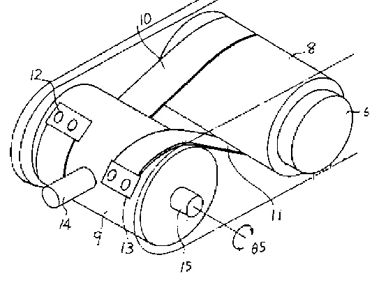
The Figure illustrates a friction gearing comprising rollers (8) and (9) attached to belts (10) and (11). The belts (10) and (11) allow the gearing to convey limited rotary motion, i.e. oscillating motion.
This place covers:
Illustrative example of subject matter classified in this place:

The Figure illustrates a friction gearing comprising input belt (6), output belt (3) and pulley (12). The gearing converts the reciprocating input motion of belt (6) into a reciprocating output motion of belt (3).
This place covers:
Illustrative example of subject matter classified in this place:

The Figure illustrates a transmission comprising gears (11) and shaft (22), which frictionally engage. Rotation of shaft (22) results in an axial movement of the carrier (24).
Gearings comprising screw mechanisms for conveying or interconverting oscillating or reciprocating motions are covered by F16H 25/20. This classification place covers similar gearings with the difference that a frictionally engaging shaft is used instead of a threaded shaft.
Attention is drawn to the following places, which may be of interest for search:
Screw mechanisms | |
Screw mechanisms with rollers |
This place covers:
Mechanisms including flexible members, where the output movement is half or double compared with the movement of the input.
Illustrative examples of subject matter classified in this place:
1.
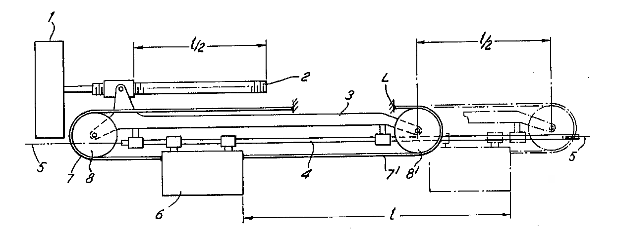
Figure 1 illustrates a transmission including rotary motor (1) and output (6). Motor (1) drives frame (3) along a linear track (5). The frame is coupled to output (6) via belts (7), (7'). Movement of frame (3) along a distance (1/2) creates movement of output (6) along a distance (l).
2.

Figure 2 illustrates a transmission including piston (2) and output (11). Piston (2) provides input to belt (9) by movement back and forth in cylinder (3). Belt (9) engages rollers (10) and is connected to output (11), such that movement of the piston (2) is doubled at output (11).
This place covers:
Mechanisms including flexible members, where the differential effect by using at least one drum or pulley with different diameters is creating the reciprocating movement.
Illustrative example of subject matter classified in this place:
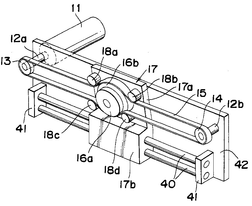
The Figure illustrates a transmission including rotary input (11) and reciprocating output (17b). Rotation of the belt (15) around pulleys (16a) and (16b) of different diameter create the reciprocating output movement of output (17b).
This place covers:
Illustrative examples of subject matter classified in this place:
1.

Figure 1 illustrates a transmission including input pinion (14) and output toothed rack (10). Pinion (14) drives toothed belt (11) which engages with toothed rack (10).
2.

Figure 2 illustrates a transmission including rotary input (24) and output toothed rack (60). Input (24) drives belt (40) which engages toothed rack (60).
This place covers:
Mechanisms where the on-winding and off-winding on a drum or thread create axial movement parallel to the drum or thread.
Illustrative example of subject matter classified in this place:

The Figure illustrates a transmission including rotary input (11) and reciprocating output (13). Winding and unwinding of thread (29) converts the rotary motion of input (11) to axial movement of output (13).
This place covers:
Mechanisms where oscillating movement is converted into reciprocating movement perpendicular to the axis of oscillation or vice versa, e.g. by on-winding and off-winding a flexible member on a drum or pulley.
Illustrative example of subject matter classified in this place:

The Figure illustrates a transmission including an input stepped motor (7) and an output carriage (2). Motor (7) drives pulley (6) which engages with belt (5). Movement of belt (5) causes axial movement of carriage (2). The axial movement of carriage (2) is perpendicular to the axis of the stepped motor (7).
This place covers:
Mechanisms where oscillating movement is converted by on-winding and off-winding of a flexible member on a drum into reciprocating movement perpendicular to the axis of oscillation.
Illustrative example of subject matter classified in this place:
1.

Figure 1 illustrates a transmission including oscillating input (12) and reciprocating output (22). Input (12) causes winding and unwinding of belt (20) at different ends, which causes reciprocating movement of output (22) perpendicular to the input motion.
2.

Figure 2 illustrates a transmission including oscillating input (26) and reciprocating output (14). Input (26) causes winding and unwinding of belt (16) at different ends, which causes reciprocating movement of output (14) perpendicular to the input motion.
3.

Figure 3 illustrates a transmission including oscillating input (11) and reciprocating output (71). Input (11) causes winding and unwinding of belts (51) and (61) at different ends, which causes reciprocating movement of output (71) perpendicular to the input motion.
This place covers:
Gearings comprising essentially only toothed gears or friction members and not capable of conveying indefinitely-continuing rotary motion, whereby the gearings are for interconverting rotary (or oscillating) motion and reciprocating motion and comprise a flexible member, the flexible member being a non-buckling chain.
Illustrative examples of subject matter classified in this place:
1.

Figure 1 illustrates a transmission including two belts (1, 1') and rotary pinions (15, 15', 17), and (17') engaging the belts. Buckling of the belts (1, 1') is prevented by interlocking teeth (2, 2').
2.

Figure 2 illustrates a transmission including belt (110) and rotary pinions (240) engaging the belt. Buckling of the belt (110) is prevented by interlocking teeth (112).
Attention is drawn to the following places, which may be of interest for search:
Devices, e.g. jacks, adapted for uninterrupted lifting of loads with racks actuated by pinions and comprising pivotable toothed sections or segments, e.g. arranged in pairs | |
Chains having special overall characteristics: stiff; Push-pull chains |
In patent documents, the following words/expressions are often used as synonyms:
- "zip chain" and "interlocking chain"
This place covers:
Toothed or friction gearing not capable of conveying indefinitely-continuing rotary motion for converting rotary or oscillating motion and reciprocating motion, comprising a flexible push member which includes a stiffness capable of creating a pushing force.
Illustrative examples of subject matter classified in this place:
1.

Figure 1 illustrates a transmission including flexible member (3) and rotary output (5). A pushing force on member (3) causes rotation of member (5).
2a.

2b.
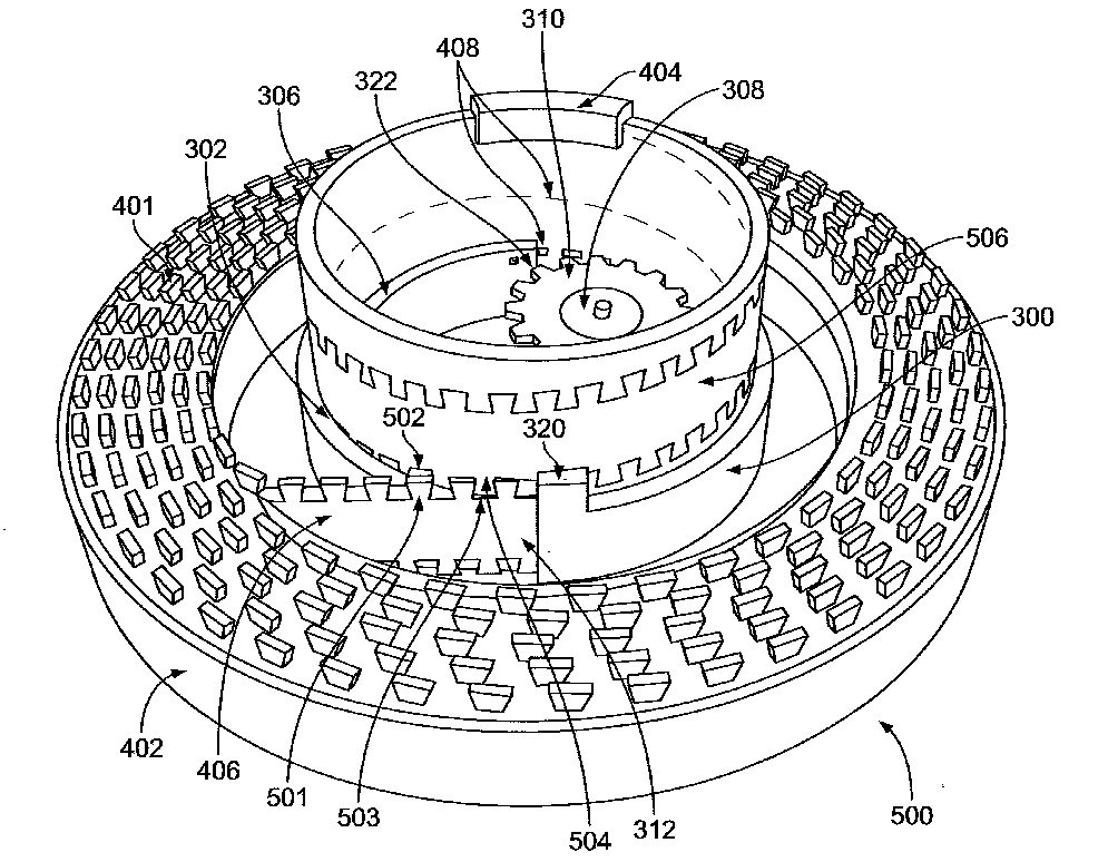
Figures 2a and 2b illustrate a gearing including rotary input pinion (308) and output (404). Rotation of pinion (308) causes flexible member (401) to wind around drum (403), causing the drum (403) and output (404) to move linearly. Flexible member (401) includes a stiffness capable of creating a pushing force in section (406).
This place covers:
Illustrative example of subject matter classified in this place:

The Figure illustrates a gearing including input worm (10) engaging with flexible rack cable (6). Sheath (7) acts as guiding means for the cable (6).
This place does not cover:
The flexible member being a non-buckling chain |
This place covers:
Illustrative examples of subject matter classified in this place:
1.
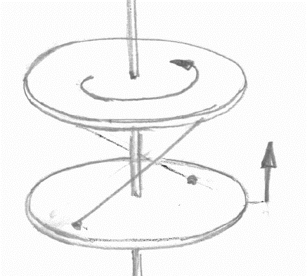
Figure 1 illustrates a gearing where rotation of the top disc causes flexible members to move bottom disc axially.
2.

Figure 2 illustrates a gearing including discs (32) and (38) and flexible members (36). Rotation of disc (32) creates reciprocating movement of disc (38).
3.

4.

Figure 4 illustrates a gearing including discs (20) and (22) and flexible members (24). Rotation of disc (20) creates reciprocating movement of disc (22).
This place covers:
Illustrative example of subject matter classified in this place:

The Figure illustrates a gearing including rotational input (11) and reciprocating output (13). Twisting movement of flexible member (12) causes the reciprocating movement of output (13), which modifies the axial length of the gearing as a whole.
This place covers:
Illustrative example of subject matter classified in this place:
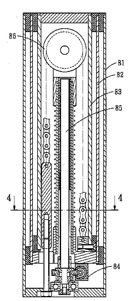
The Figure illustrates a gearing including input from motor (84) and telescoping pipes (81, 82 and 83). Motor (84) causes rotation of screw (85), which causes rotation of pulley (86). Rotation of pulley (86) causes axial displacement of pipes (81, 82 and 83) via a chain.
This place covers:
Illustrative example of subject matter classified in this place:
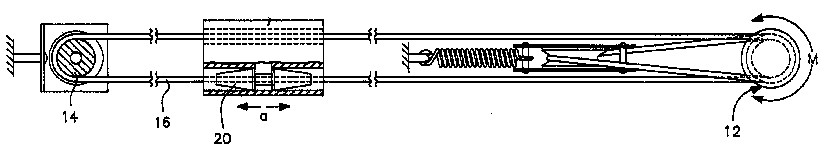
The Figure illustrates a gearing including rotary input (12) and reciprocating output (20). A spring is included for tensioning the flexible member (16).
Attention is drawn to the following places, which may be of interest for search:
Means for varying tension of belts, ropes or chains for gearings conveying rotary motion |
This place covers:
Example:
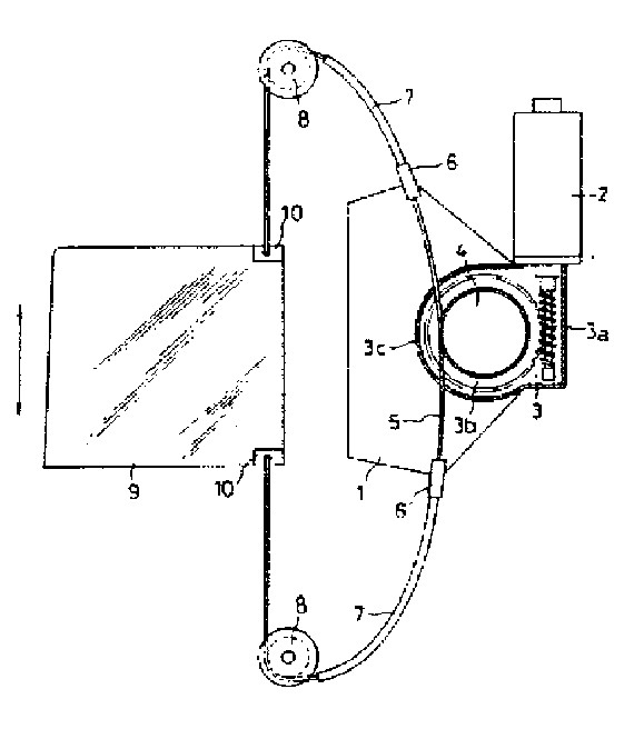
This place covers:
Illustrative example of subject matter classified in this place:

The Figure illustrates a gearing including rotary input (930) and reciprocating output (900). The flexible member (910) forms a closed loop (i.e. the flexible member is endless).
This place covers:
Illustrative example of subject matter classified in this place:
1a.

1b.

1c.

Figures 1a, 1b and 1c illustrate a gearing including rotary inputs (64 and 74), block (30) slidable in both the vertical (Z) and horizontal (R) directions, flexible member (56) and moveable output (18). Actuation of the gearing allows output (18) to be moved to a specific location on the (R-Z) plane.
This place covers:
Illustrative example of subject matter classified in this place:
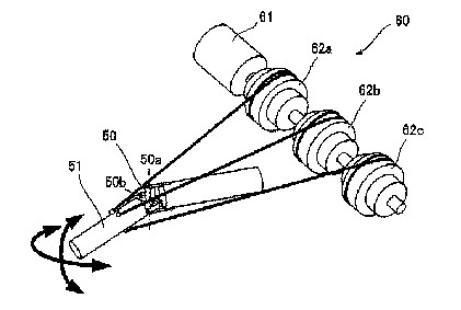
The Figure illustrates a gearing including rotary input from motor (61) and output (51). Actuation of the gearing generates a pivoting movement at (50) for output (51).
Attention is drawn to the following places, which may be of interest for search:
Positioning means for manipulators with cables, chains or ribbons |
This place does not cover:
Wobble-plate gearings; Oblique-crank gearings |
Attention is drawn to the following places, which may be of interest for search:
Combinations of gearings of different types | |
Portable or mobile lifting or hauling appliances | |
Crankshafts or eccentric shafts per se | |
Adjustable cranks or eccentric shafts per se | |
Adjustable connecting rods per se |
This place covers:
Illustrative example of subject matter classified in this place:

The Figure illustrates a gearing including input (4), links (7) and (8), and output (6). Links (7) and (8) guide element (6).
Examples of places where the subject matter of this place is covered when specially adapted, used for a particular purpose, or incorporated in a larger system:
Guiding mechanisms for drawing-machines |
This place covers:
Illustrative example of subject matter classified in this place:
1a.

1b.

Figures 1a and 1b illustrate a gearing comprising input member (185) and output member (187). Crank pin (104) is fixed on rotary member (185) and guided in a first long hole of member (202), crank pin (106) is fixed on rotary member (187) and guided in a second long hole of member (202). Counter-clockwise rotation of rotary input member (185) is conveyed to clockwise rotation of rotary output member (187) via reciprocating motion of member (202).
Attention is drawn to the following places, which may be of interest for search:
Toothed gearings for conveying rotary motion with constant gear ratio, with gears having orbital motion in which the central axis of the gearing lies inside the periphery of an orbital gear, with the orbital gear having internal gear teeth |
Attention is drawn to the following places, which may be of interest for search:
Eccentric gearing with toothed gears having orbital motion |
This place covers:
Gearings comprising primarily only links or levers, with or without slides, crank gearings or eccentric gearings, for interconverting rotary motion and reciprocating motion, all movement being in, or parallel to, a single plane, with adjustment of throw.
Illustrative examples of subject matter classified in this place:
1.

Figure 1 illustrates a crank gearing comprising primarily only links and levers for converting rotary motion of the crank shaft (1) into reciprocating motion of the piston (13) which functions as a guided slide. Crankshaft (1) comprises an oblique crank pin (9). The throw, i.e. the length of the reciprocating motion of piston (13), is adjusted by moving crankshaft (1) in a different axial position. The axial movement of crankshaft (1) between a minimum and maximum throw is shown by arrow (7).
2.

Figure 2 illustrates a crank gearing comprising primarily only links and levers for converting rotary motion of the crank shaft (18) into reciprocating motion of the piston (13) which functions as a guide slide. The throw, i.e. the length of the reciprocating motion of piston (13), is adjusted by moving pivot (12) to a different position.
Examples of places where the subject matter of this place is covered when specially adapted, used for a particular purpose, or incorporated in a larger system:
Engines with variable distances between pistons at top dead-centre positions and cylinder heads by means of a variable crank stroke length |
Attention is drawn to the following places, which may be of interest for search:
Gearings comprising primarily only cams, cam followers and screw-and-nut mechanisms for interconverting rotary motion and reciprocating motion, with adjustable throw | |
Adjustable cranks or eccentrics | |
Adjustable connecting-rods |
Attention is drawn to the following places, which may be of interest for search:
With two or more connecting-rods to each crank or eccentric | |
Other engines characterised by connections between pistons and main shafts |
This place covers:
Illustrative example of subject matter classified in this place:
1a.

1b.

Figures 1a and 1b illustrate a crank gearing comprising primarily only links or levers for converting rotary motion of crank shaft (21) into reciprocating motion of piston (14) which functions as a guided slide via connecting rod (7). The crank gearing does not comprise any further links or guides in addition to the one connecting rod (7) and one guided slide (14).
Attention is drawn to the following places, which may be of interest for search:
With cams or additional guides | |
With additional members comprising only pivoted links or arms |
This place covers:
Crank gearings or eccentric gearings comprising primarily only links or levers, for interconverting rotary motion and reciprocating motion. All movement is in, or parallel to, a single plane, with one connecting-rod and one guided slide to each crank or eccentric. The gearing includes joints or levers which may toggle, or move, between two locations.
Attention is drawn to the following places, which may be of interest for search:
With additional members comprising only pivoted links or arms |
In patent documents, the following words/expressions are often used as synonyms:
- "Toggle joint", "Knee joint", "Toggle lever" and "Knee lever"
This place covers:
Illustrative examples of subject matter classified in this place:
1.

Figure 1 illustrates a crank gearing comprising primarily only links or levers for converting rotary motion of crank shaft (11) into reciprocating motion of piston (1) which functions as a guided slide. Crank pin (8) moves along groove (6), such that groove (6) functions as a cam. Connecting rod (7) is guided by crosshead (12) functioning as an additional guide.
2.

Figure 2 illustrates a crank gearing comprising primarily only links or levers for converting rotary motion of the crank shaft into reciprocating motion of the piston which functions as a guided slide. The gearing further includes a crosshead a functioning as an additional guide.
3a.

3b.

Figures 3a and 3b illustrate a crank gearing comprising primarily only links or levers for converting rotary motion of crank shaft (k) into reciprocating motion of piston (b) which functions as a guided slide. Pin (d) at the lower end of connecting rod (c) interacts with a cam (g) as well as a long hole (h) which also functions as a cam of crank arm (i).
This place covers:
Illustrative example of subject matter classified in this place:

The Figure illustrates a crank gearing for converting rotary motion of one crank shaft (4) into reciprocating motion of one piston (1) (guided slide) via one connecting rod (21) and by using gears (24) and (25) as members having rolling contact.
Attention is drawn to the following places, which may be of interest for search:
Crank gearings comprising primarily only links or levers with all movement being in, or parallel to, a single plane, for interconverting rotary motion and reciprocating motion, without swinging connecting-rod, with orbital gearing having a ratio of 2:1 between central gear and orbital gear |
In this place, the following terms or expressions are used with the meaning indicated:
members having rolling contact | e.g. a pair of toothed gears or a toothed pinion gear meshing with a rack. |
This place covers:
Illustrative example of subject matter classified in this place:

The Figure illustrates a crank gearing comprising primarily only links and levers for converting rotary motion of crank shaft (A) into reciprocating motion of piston (F) which functions as a guided slide. Crank pin (B) is connected to connecting rod (F-E) via additional pivoted links (B-C), (C-E) and (G-E).
Attention is drawn to the following places, which may be of interest for search:
With toggle action |
This place covers:
Illustrative examples of subject matter classified in this place:
1.

Figure 1 illustrates a crank gearing comprising primarily only links or levers for converting rotary motion of crank shaft (S) into reciprocating motion of two pistons (P), which two pistons function as guided slides. Two respective connecting rods (2') and (4') are connected to a single crank (14).
2.

Figure 2 illustrates a crank gearing including primarily only links or levers for converting rotary motion of a crank shaft (9) into reciprocating motion of five pistons (6), which pistons function as guided slides. Five respective connecting rods (10) are connected to a single crank (9).
Attention is drawn to the following places, which may be of interest for search:
With one connecting-rod and one guided slide to each crank or eccentric |
This place covers:
Illustrative examples of subject matter classified in this place:
1a.

1b.

Figures 1a and 1b illustrate an eccentric gearing including a crankshaft (11), eccentric member (9), rod (6) and piston (13). Rotary motion of crankshaft (11) with eccentric member (9) is converted into reciprocating motion of piston (13) which functions as a guided slide. Rod (6) moves only linearly and does not swing.
2.

Figure 2 illustrates a crank gearing including primarily only links or levers for converting rotary motion of the crank shaft into reciprocating motion of the piston functioning as a guided slide. The crank pin is running in a cam-like slot, which generates a slot-and-crank motion. The connecting rod does not swing.
Attention is drawn to the following places, which may be of interest for search:
Gearings comprising primarily only cams, cam followers, and screw-and-nut mechanisms for interconverting rotary motion and reciprocating motion, with reciprocation perpendicular to the axis of rotation |
This place covers:
Illustrative example of subject matter classified in this place:
1a.

Figure 1a illustrates an eccentric gearing including a crank (10), (12), (13) which rotatably carries orbital gear (19), and further including ring gear (14), rod (21) and piston (8). Rotary motion of crank (10), (12), (13) and orbital gear (19) is converted into reciprocating motion of piston (8) which functions as a guided slide. Rod (21) moves only linearly and does not swing. The orbital gearing includes a ratio of 2:1 between the ring gear (14) and the orbital gear (19).
1b.

This place covers:
Gearings using rotating wobble plates or discs for converting rotary movement into a reciprocating movement of a gear member.
Attention is drawn to the following places, which may be of interest for search:
Gearings with toothed wobble members for conveying rotary motion, e.g. reduction gears with high ratio | |
Combinations of gearings of different types |
This place covers:
- Gearings using primarily only cams or cam-followers to convey rotary motion;
- Other gearings comprising primarily only cams or cam-followers for interconverting oscillating and reciprocating motions;
- Screw-and-nut-mechanisms.
Attention is drawn to the following places, which may be of interest for search:
Crank gearings or eccentric gearings comprising primarily only links or levers | |
Wobble plate gearings or oblique-crank gearings | |
Combinations of mechanical gearings of different types | |
Adjustable single-track cams per se for single-revolution cycles; Camshafts with such cams per se | |
Cam followers per se | |
Rope or like tackle for lifting or haulage | |
Adjustable connecting rods per se | |
Clutch actuation by cams, ramps or ball-screw-mechanisms |
Attention is drawn to the following places, which may be of interest for search:
Combinations of mechanical gearings, not provided for in groups F16H 1/00 - F16H 35/00, comprising primarily toothed or friction gearing, links or levers, and cams, or members of at least two of these types, the movements of two or more independently moving members being combined into a single movement |
This place covers:
Gearings comprising primarily only cams and cam followers for conveying rotary motion.
Illustrative examples of subject matter classified in this place:
1.

Figure 1 illustrates a cam gearing comprising only sphere (1) with a cam groove and disc (5) with cam follower pin (6). Rotary motion (4) of sphere (1) causes rotary motion (7) of disc (5).
2.

Figure 2 illustrates a screw-and-nut gearing (10) comprising only nut (12) and circular screw (14). Rotary motion (R1) of nut (12) causes rotary motion (R2) of circular screw (14).
Attention is drawn to the following places, which may be of interest for search:
Toothed gearings for conveying rotary motion | |
Gearing for conveying rotary motion with constant gear ratio by friction between rotary members | |
Step-by-step mechanisms without freewheel members, for converting continuous rotation into a step-by-step rotary movement, comprising a member with partially helical tracks | |
Gearings for conveying rotary motion with intermittently-driving members, e.g. with freewheel action | |
Wave gearings, e.g. harmonic drive transmissions |
Attention is drawn to the following places, which may be of interest for search:
Toothed gearings for conveying rotary motion with gears having orbital motion where the central axis of the gearing lies inside the periphery of an orbital gear, e.g. eccentric gearing or cycloidal gearing | |
Wave gearings, e.g. harmonic drive transmissions |
This place covers:
Illustrative examples of subject matter classified in this place:
1a.

1b.

Figures 1a and 1b illustrate a cam gearing comprising rotary input (90) and rotary output (100). Balls (80) engage opposite cam discs, e.g. discs (110 and 112).
2.

Figure 2 illustrates a cam gearing comprising a rotary input and rotary output. Balls (9) and (10) engage opposite cam discs (1) and (2).
This place covers:
Gearings comprising primarily only cams and cam followers for interconverting rotary motion and reciprocating motion.
Note: When reversing reciprocating motion, input rotary motion (which is defined as indefinitely continuous rotary motion) would cause an automatic reversal of the reciprocating motion. If the input rotational direction is changed in order to cause reversal of the reciprocating motion, the input motion is an oscillating motion (which is defined as alternately forward and backward rotary motion).
Illustrative example of subject matter classified in this place:

The Figure illustrates a gearing comprising only a cam (7) and a cam follower (12). Rotary motion of shaft (5) is converted into reciprocating motion of rod (14) see arrows (15) via the cam (7) and cam follower (12).
This place does not cover:
Wobble-plate gearings; Oblique-crank gearings |
Attention is drawn to the following places, which may be of interest for search:
Gearings comprising primarily only cams, cam-followers and screw-and-nut mechanisms for conveying or interconverting oscillating or reciprocating motions |
This place covers:
Gearings comprising primarily only cams and cam followers for interconverting rotary motion and reciprocating motion, with adjustable throw.
Illustrative example of subject matter classified in this place:
1a.

1b.

1c.

Figures 1a, 1b and 1c illustrate a gearing comprising only a cam (38) and a cam follower (42). Rotary motion of cam (38) is converted into reciprocating motion of cam follower (42). The throw (i.e. the length of the reciprocating motion), is adjusted by axially moving axially tapered cam (38).
Examples of places where the subject matter of this place is covered when specially adapted, used for a particular purpose, or incorporated in a larger system:
Modifications of valve-gear for optimising engine performances by modifying valve lift according to various working parameters |
Attention is drawn to the following places, which may be of interest for search:
Crank gearings or eccentric gearings comprising primarily only links or levers, for interconverting rotary motion and reciprocating motion in or parallel to a single plane, with adjustment of throw | |
Adjustable cams |
This place covers:
Gearings comprising primarily only cams and cam followers for interconverting rotary motion and reciprocating motion, with reciprocation occurring in a direction along the axis of rotation. It is noted that "reciprocation along the axis of rotation" can be reciprocating movement either on or parallel to the axis of rotation.
Illustrative examples of subject matter classified in this place:
1a.

Figure 1a illustrates a gearing comprising only a cam shaft (4) and a cam follower (12). Rotary motion of the input shaft (see arrow 8) is converted into reciprocating motion of output shaft (14) (see arrow F, s). The reciprocation is along and coaxial to the axis of rotation (10). The gearing comprises wave-type profiles (22) and (24) for the cam.
1b.

2.

Figure 2 illustrates a gearing comprising only a cam (14) and a cam follower (9). Rotary motion of shaft (17) is converted into reciprocating motion of sledge (6) (see arrow 7). The reciprocation is along and parallel to the axis of rotation. The gearing includes helical projection (14).
Attention is drawn to the following places, which may be of interest for search:
Gearings comprising primarily only cams, cam-followers and screw-and-nut mechanisms for conveying or interconverting oscillating or reciprocating motions | |
Screw mechanisms without automatic reversal |
This place covers:
Illustrative example of subject matter classified in this place:

The Figure illustrates a gearing comprising only a cam shaft (3) and a cam follower (1). Rotary motion of cam shaft (3) is converted into reciprocating motion of output (6). The reciprocation is along and parallel to the axis of rotation. Cam shaft (3) has an endless helical groove (4) which provides an automatic reversal of output (6) via cam follower (1).
This place covers:
Illustrative example of subject matter classified in this place:
1a.

1b.

Figures 1a and 1b illustrate a gearing comprising only a cam shaft (4) and a cam follower (5). Rotary motion of shaft (2) is converted into reciprocating motion of shaft (3). The reciprocation is along and coaxial to the axis of rotation. Cam shaft (4) includes a cam provided on an end surface of rotary cam shaft (4).
This place covers:
Illustrative example of subject matter classified in this place:
1a.

Figure 1a illustrates a gearing comprising a gearing comprising a fixed base (11), cam shafts (22), (23) and (24), a cam follower comprised of apertures (A-M) and an output shaft (12). Reciprocating motion of each of the cam shafts (22), (23) and (24) is induced by respective solenoids (29). This motion is converted into rotary motion of output shaft (12) see arrow (30) via lateral force (39). The reciprocation is along and parallel to the axis of rotation.
1b.

1c.

This place covers:
Gearings comprising primarily only cams and cam followers for interconverting rotary motion and reciprocating motion, with reciprocation occurring in a direction perpendicular to the axis of rotation.
Illustrative examples of subject matter classified in this place:
1.

Figure 1 illustrates a gearing comprising only a cam (22) and a cam follower (20). Rotary motion of cam (22) is converted into reciprocating motion of cam follower (20). Reciprocation is perpendicular to the axis of rotation of the cam (22).
2a.

2b

Figures 2a and 2b illustrate a gearing comprising only a cam (38) and a cam follower (36). Rotary motion of cam shaft (32) is converted into reciprocating motion of piston (122). Reciprocation is perpendicular to the axis of rotation of cam shaft (32).
This place does not cover:
Crank or eccentric gearings comprising primarily only links or levers without swinging connecting-rod |
Examples of places where the subject matter of this place is covered when specially adapted, used for a particular purpose, or incorporated in a larger system:
Valve drives by means of cams, camshafts, cam discs, eccentrics or the like |
This place covers:
Gearings comprising primarily only cams and cam followers for interconverting rotary motion and oscillating motion.
Illustrative example of subject matter classified in this place:
1a.

1b.

Figures 1a and 1b illustrate a gearing comprising primarily only a cam (h) and a cam follower (i). Rotary motion of shaft (d) is converted into oscillating motion of lever (a) and output shaft (b).
It is noted that the gearing comprises a single lever (a). However, the primary functioning of the gearing consists of a cam and cam follower, and the presence of a single lever is not sufficient to consider the gearing as more than primarily cams and cam followers.
Attention is drawn to the following places, which may be of interest for search:
Step-by-step mechanisms without freewheel members, for converting continuous rotation into a step-by-step rotary movement, comprising a member with partially helical tracks | |
Combinations of mechanical gearings, not provided for in groups F16H 1/00 - F16H 35/00, comprising primarily toothed or friction gearing, links or levers, and cams, or members of at least two of these types |
This place covers:
Gearings comprising primarily only cams and cam followers, for conveying or interconverting oscillating or reciprocating motions.
Illustrative examples of subject matter classified in this place:
1.

Figure 1 illustrates a gearing comprising only a cam (12) and a cam follower (23). Oscillating motion of cam (12) is converted into reciprocating motion (31) and (33) of shaft (22).
2.

Figure 2 illustrates a gearing comprising primarily only a cam (11) and a cam follower (16). Oscillating motion of shaft (7) is conveyed into oscillating motion of lever (4).
It is noted that the gearing comprises a single lever (4). However, the primary functioning of the gearing consists of a cam and cam follower, and the presence of a single lever is not sufficient to consider the gearing more than primarily cams and cam followers.
Attention is drawn to the following places, which may be of interest for search:
Combinations of mechanical gearings, not provided for in groups F16H 1/00 - F16H 35/00, comprising primarily toothed or friction gearing, links or levers, and cams, or members of at least two of these types |
This place covers:
Illustrative examples of subject matter classified in this place:
1.

Figure 1 illustrates a gearing comprising cams in the form of wedges. A horizontal reciprocating movement of the lower wedge is conveyed into a vertical reciprocating movement of the upper wedge.
2.

Figure 2 illustrates a gearing comprising cams in the form of wedges (10), (12) and (14). A horizontal reciprocating movement of wedges (10) and (12) in opposite directions is conveyed into a vertical reciprocating movement of wedge (14).
3.

Figure 3 illustrates a gearing comprising cams in the form of wedges (9), (7) and (8). A reciprocating horizontal movement of wedge (9) is conveyed into reciprocating horizontal movement of wedge (8) via ball (1) and wedge (7).
This place covers:
Illustrative examples of subject matter classified in this place:
1a.

1b.

Figures 1a and 1b illustrate a gearing comprising only cam shaft (4a) and cam follower (5a), which convert oscillating motion of input (11) to reciprocating motion of output (2). Reciprocating motion of output (2) is along the axis of oscillation of input (11).
2.

Figure 2 illustrates a gearing comprising only cam (2) and cam follower (3), which convert reciprocating motion of input (1) to oscillating motion of output (4). Reciprocating motion of output (4) is along the axis of oscillation of input (1).
Attention is drawn to the following places, which may be of interest for search:
Means for influencing the pressure between members in friction gearing with constant ratio for automatically varying the pressure mechanically | |
Means for controlling the torque transmitting capability of continuously variable gearing with endless flexible members | |
Means for controlling the torque transmitting capability of continuously variable friction gearing |
In patent documents, the following words/expressions are often used as synonyms:
- "Ball-ramp mechanism"
- "Clamping force generator", "axial force generator" or "thrust generator"
- "Cam disc" or "disk"
This place covers:
Illustrative examples of subject matter classified in this place:
1.

Figure 1 illustrates a gearing comprising primarily only a screw-and-nut mechanism. Rotation of screw (6) results in linear movement of nut (8).
2.

Figure 2 illustrates a gearing comprising primarily only a screw-and-nut mechanism. Rotation of nut (23) results in linear movement of screw (40). It is noted that the gearing comprises a simple set of toothed gears (20). However, the primary functioning of the gearing consists of the screw and nut, and the presence of a simple set of gears is not sufficient to consider the gearing more than primarily a screw-and-nut mechanism.
This place does not cover:
Gearings comprising primarily only cams and cam followers for interconverting rotary motion and reciprocating motion with reciprocation along the axis of rotation |
Attention is drawn to the following places, which may be of interest for search:
Gearings comprising friction members and not capable of conveying indefinitely-continuing rotary motion comprising a friction shaft | |
Screw-operated jacks | |
Handling mechanical energy associated with electric machines including means for converting reciprocating motion into rotary motion or vice-versa |
This place covers:
Illustrative examples of subject matter classified in this place:
1a.

1b.

Figures 1a and 1b illustrate a gearing comprising primarily only a screw-and-nut mechanism. Guide members (16) move along guide surface (15) of the housing (2) to support and guide the nut (4).
2.

Figure 2 illustrates a gearing comprising primarily only a screw-and-nut mechanism having a nut (3) and a rotatable screw (53). Nut (3) comprises axial sliding means in the form of flat surfaces which slide on axial guide surfaces (86) and (87) of housing (81), thereby preventing rotation of nut (3) while at the same time allowing its axial movement.
Attention is drawn to the following places, which may be of interest for search:
Common movement by two screws or two nuts, e.g. two connected screws with opposite thread direction |
This place covers:
Illustrative examples of subject matter classified in this place:
1a.

1b.

Figures 1a and 1b illustrate a gearing comprising primarily only a screw-and-nut mechanism having screws (22) and (32) engaging nuts (24) and (34), respectively. Nuts (24) and (34) are connected to each other and have opposite thread directions. Common rotation of nuts (24) and (34) results in opposite linear movement of screws (22) and (32).
2.

Figure 2 illustrates a gearing comprising primarily only a screw-and-nut mechanism having screws (31) and (32) engaging nuts (41) and (42) respectively. Screws (31) and (32) are connected to each other and have opposite thread directions. Common rotation of screws (31) and (32) results in opposite linear movement of nuts (41) and (42).
Attention is drawn to the following places, which may be of interest for search:
Telescopic screws with at least three screw members in coaxial arrangement |
This group and subgroup F16H 25/2204 are only given if the subject-matter of the cooperating parts, e.g. the circulating balls are of particular interest representing the invention information. If the ball screw device is just an additional feature invention classification is given in group F16H 25/20.
This place does not cover:
Screw mechanisms with balls, rollers or similar members between the co-operating parts; Elements essential to the use of such members |
Attention is drawn to the following places, which may be of interest for search:
Features relating to lubrication or cooling or heating of screw mechanisms |
This place covers:
Mechanisms which include movement in a stepwise, or step-by-step, manner such that an output member is alternately moving and at rest during continuous motion of an input member.
Attention is drawn to the following places, which may be of interest for search:
Rotary gearings with cyclically-varying velocity ratio | |
Impulse couplings | |
Clockwork escapements |
In patent documents, the following words/expressions are often used as synonyms:
- "step-by-step", "stepwise" and "indexing"
This place covers:
Illustrative examples of subject matter classified in this place:
1.

Figure 1 illustrates a step-by-step mechanism having a reciprocating rod (14) as an input member. Reciprocating movement of rod (14) and its attached pin (13) creates a step-by-step rotary movement of output member (1). During reciprocating movement of rod (14), output member (1) is at rest until the pin (13) arrives at groove surface (10b), as shown in illustration (A) and (B). When pin (13) impacts groove surface (10b) it forces output member (1) to rotate, as shown in illustration (C). Rotation of output member (1) stops when pin (13) arrives at groove surface (10c). Thereafter, during the continued reciprocating movement of rod (14) and its pin (13), output member (1) is again at rest. Continuous reciprocation of rod (14) results in a stepwise rotation of output member (1).
2.

Figure 2 illustrates a gearing including a rotary input gear (2) with interrupted toothing (8a) and (8b) and a reciprocating rack (3) as an output member. Continuous rotation of input gear (2) results in a stepwise linear movement of rack (3).
This place covers:
Illustrative example of subject matter classified in this place:
1a.

1b.

Figures 1a and 1b illustrate a gearing including a rotary input member (30) with a helical rib (38) having tracks (39) and (40), and a rotary output member (35) with cam followers (36) which interact with tracks (39) and (40). Continuous rotation of input member (30) is converted into a step-by-step rotation of output member (35). When one of the followers (36) engages with a straight section of helical rib (38), output member (35) is at rest. When one of the followers (36) engages with an oblique section of helical rib (38), the helical rib (38) drives follower (36) such that output member (35) is rotated about an angle of 45°. Thus, the continuous rotation of input member (30) results in a stepwise rotation of output member (35).
Attention is drawn to the following places, which may be of interest for search:
Cam gearings for conveying rotary motion | |
Cam gearings for interconverting rotary motion and oscillating motion |
This place covers:
Illustrative example of subject matter classified in this place:

The Figure illustrates a gearing including rotary input shaft (Δ1) and rotary output shaft (Δ2). Continuous rotation of input shaft (Δ1) is converted into a step-by-step rotation of output shaft (Δ2). When driving pin (13) is within one of driven slots (1210), (1220), (1230) or (1240), output shaft (Δ2) is rotated about an angle of 90°. When driving pin (13) is outside of any driven slot, output shaft (Δ2) is at rest. Thus, the continuous rotation of input shaft (Δ1) results in a stepwise rotation of output shaft (Δ2). This type of gearing is considered a Geneva drive.
This place covers:
Illustrative example of subject matter classified in this place:

The Figure illustrates a gearing including a rotary input gear (2) with interrupted toothing (8) and a rotary output gear (3). Continuous rotation of input gear (2) results in a stepwise rotation of output gear (3).
This place covers:
Gearings for conveying continuous rotary motion into a rotary output motion by using intermittently-driving members, e.g. with freewheel action:
- with stationary intermittently-driving members, i.e. not rotating with either of the shafts;
- with rotating intermittently-driving members.
Attention is drawn to the following places, which may be of interest for search:
Other gearings with freewheeling members or other intermittently driving members | |
Adjustable cranks or eccentrics | |
Freewheels or freewheel clutches |
This place covers:
Gearings for conveying rotary motion from an input shaft to rotary motion of an output shaft, and including intermittently driving members, e.g. members with freewheel action. The intermittently driving members are located between one of the input and output shafts and an oscillating or reciprocating intermediate member. The intermittently driving members do not rotate with either of the input or output shafts.
This place does not cover:
Gearings for conveying rotary motion with intermittently driving members, e.g. with freewheel action, the intermittently acting members being shaped as worms, screws or racks | |
Gearings for conveying rotary motion with intermittently driving members, e.g. with freewheel action, with automatic speed change |
This place covers:
Illustrative example of subject matter classified in this place:
1a

1b.

Figures 1a and 1b illustrate a crank CVT including a rotary driving shaft (4), a rotary driven shaft (5), an adjustable eccentric (6), several cranks (8) and a freewheel clutch (7) between each of the cranks (8) and the driven shaft (5). Each crank (8) is considered an oscillating intermediate member, which does not rotate with either the drive shaft (4) or driven shaft (5). Each freewheel clutch (7) is regarded as an intermittently-driving member between each of the cranks (8) and driven shaft (5).
This place covers:
Illustrative example of subject matter classified in this place:

The Figure illustrates a gearing including levers (13) arranged between rotary driving shaft (1) and rotary driven shaft (5). Each lever (13) drives the driven shaft (5) only if it is the lever closest to teeth (7). Thus, each lever drives only intermittently and is considered as an intermittently-driving member between driving shaft (1) and driven shaft (5).
This place does not cover:
Gearings for conveying rotary motion with intermittently driving members, e.g. with freewheel action, the intermittently acting members being shaped as worms, screws or racks | |
Gearings for conveying rotary motion with intermittently driving members, e.g. with freewheel action, with automatic speed change |
This place covers:
Illustrative example of subject matter classified in this place:
1a.

1b.

Figure 1a illustrates a gearing including a driving shaft (20), a driven shaft (24) and levers (25). Each lever (25) drives the driven shaft (24) only if it is the lever closest to teeth (21). Thus, each lever drives only intermittently and is considered as an intermittently driving member between driving shaft (20) and driven shaft (24). The transmission ratio is changed by adjustment of the distance (eccentricity) between driving shaft (20) and driven shaft (24). Figure 1b illustrates a transmission ratio different from 1:1, while Figure 1a illustrates a transmission ratio of 1:1.
This place covers:
Gearings with freewheeling members or other intermittently-driving members for converting oscillating, i.e. non-continuous rotary input, or reciprocating movement into another movement, e.g. a step-by-step mechanism including a freewheel member.
This place does not cover:
Gearings comprising primarily only links or levers | |
Wobble plate or oblique crank gearings | |
Gearings comprising primarily only cams, cam-followers and screw-and-nut mechanisms |
Examples of places where the subject matter of this place is covered when specially adapted, used for a particular purpose, or incorporated in a larger system:
Wrenches of the ratchet type |
Attention is drawn to the following places, which may be of interest for search:
Gearings using freewheel members for changing ratio | |
Step-by-step mechanisms without freewheel member | |
Gearings for conveying rotary motion with intermittently-driving members or freewheel action |
Examples of places where the subject matter of this place is covered when specially adapted, used for a particular purpose, or incorporated in a larger system:
Spanners or wrenches of the ratchet type, for providing a free return stroke of the handle |
This place covers:
Mechanisms converting oscillating or reciprocating motion to rotary motion (or vice versa), which include movement in a stepwise, or step-by-step, manner such that an output member is alternately moving and at rest during continuous motion of an input member.
Attention is drawn to the following places, which may be of interest for search:
Step-by-step mechanisms without freewheel members | |
Gearings for conveying rotary motion with intermittently-driving members, e.g. with freewheel action |
This place covers:
Step-by-step mechanisms for rotary motion including an intermittently driving member, wherein the intermittently driving member includes pawls driven by a rotary cam.
This place covers:
Step-by-step mechanisms for rotary motion including an intermittently driving member, wherein the intermittently driving member includes pawls driven by a reciprocating or oscillating transmission member.
This place does not cover:
Hand-driven ratchets | |
Step-by-step mechanisms for rotary motion with pawls driven by a rotary cam |
This place covers:
Step-by-step mechanisms for rotary motion including an intermittently driving member, wherein the intermittently driving member includes friction means.
This place covers:
Mechanisms for linear motion which include movement in a stepwise, or step-by-step, manner such that an output member is alternately moving and at rest during continuous motion of an input member.
This place covers:
Step-by-step mechanisms for linear motion including an intermittently driving member, wherein the intermittently driving member includes friction means.
Examples of places where the subject matter of this place is covered when specially adapted, used for a particular purpose, or incorporated in a larger system:
Apparatus for generating mechanical vibrations involving rotary unbalanced masses |
Attention is drawn to the following places, which may be of interest for search:
Gravity or inertia motors |
Attention is drawn to the following places, which may be of interest for search:
Ratchet slip couplings |
Attention is drawn to the following places, which may be of interest for search:
For converting into a linear propulsion force, i.e. inertia motors |
This place covers:
Illustrative examples of subject matter classified in this place:
1.

Figure 1 illustrates a toothed gearing including a pair of spur gears (1) and (2) which are eccentrically mounted.
2.

Figure 2 illustrates a rack and pinion gearing having a pinion (4) which is eccentrically mounted.
3.

Figure 3 illustrates a belt-type transmission having a pulley (7) which is eccentrically mounted.
Attention is drawn to the following places, which may be of interest for search:
Toothed gearing for conveying rotary motion with gears having orbital motion in which the central axis of the gearing lies inside the periphery of an orbital gear, e.g. eccentric gearing or cycloidal gearing | |
Gearings comprising primarily only links or levers with all movement being in, or parallel to, a single plane, for conveying rotary motion by means of cranks, eccentrics or like members fixed to one rotary member and guided along tracks on the other | |
Crank gearings or eccentric gearings comprising primarily only links or levers with all movement being in, or parallel to, a single plane, for interconverting rotary motion and reciprocating motion | |
Gearings for conveying rotary motion with intermittently-driving members between one of the shafts and an oscillating or reciprocating intermediate member, not rotating with either of the shafts, in which the transmission ratio is changed by adjustment of a crank, an eccentric, a wobble-plate, or a cam, on one of the shafts | |
Gearings or mechanisms for conveying rotary motion with cyclically varying velocity ratio |
This place covers:
Illustrative examples of subject matter classified in this place:
1.

Figure 1 illustrates a toothed gearing including two non-circular gears (13) and (14).
2.

Figure 2 illustrates a toothed gearing including non-circular gear (3).
3.

Figure 3 illustrates a belt-and-pulley transmission including two non-circular pulleys.
Attention is drawn to the following places, which may be of interest for search:
Gearings or mechanisms for conveying rotary motion with cyclically varying velocity ratio | |
Harmonic drives with elliptical wave generators |
This place covers:
Illustrative example of subject matter classified in this place:

The Figure illustrates a gearing with a no-back mechanism consisting of an axially movable friction member (10). Friction member (10) and helical gear (13) are fixed to shaft (9). Only when torque is applied from output shaft (24), i.e. backdriving of the gearing, shaft (9) is axially moved by the axial force of helical gear (13) towards brake area (11), thereby pressing friction member (10) against brake area (11) of housing wall (4). This causes braking of shaft (9) and prevents backdriving of output shaft (24).
Attention is drawn to the following places, which may be of interest for search:
Unidirectionally torque-transmitting toothed gearing for conveying rotary motion | |
Brakes and rotational locks of screw mechanisms | |
Freewheels or freewheel clutches | |
Self-acting brakes |
In patent documents, the following words/expressions are often used as synonyms:
- "Brakes" or "mechanisms for preventing backdriving" and "no-back devices"
This place covers:
Illustrative examples of subject matter classified in this place:
1.

Figure 1 illustrates a worm gearing consisting of a worm (11) and a worm wheel (15). The worm wheel (15) includes end stops (21) with noses (22), which stop movement after a few turns of worm (11).
2a.

2b.

2c.

Figures 2a, 2b and 2c illustrate a toothed gearing including three spur gears (15), (16) and (17). Spur gear (17) comprises an end stop (18) which stops movement after a few turns of spur gear (15).
Attention is drawn to the following places, which may be of interest for search:
Gearings comprising essentially only toothed gears or friction members and not capable of conveying indefinitely-continuing rotary motion | |
Screw mechanisms with means specially adapted for stopping actuators in the end position, or with position sensing means |
This place covers:
Gearings or mechanisms that include means to vary the rotational phase relationship, e.g. gearings that include means to vary the angular relationship between the input and the output shaft.
Illustrative examples of subject matter classified in this place:
1a.

1b.

Figures 1a and 1b illustrate a toothed gearing (28) including input shaft (30), output shafts (32) and (34), and planetary gearing (38). The rotational phase relationship between output shafts (32) and (34) is adjusted by rotating ring gear (40) via worm (48) about an angle which corresponds to the desired phase relationship between shafts (32) and (34).
2.

Figure 2 illustrates a chain-type gearing including input sprocket (30), output sprocket (62), tensioner sprocket (64) and sprocket (40). The rotational phase relationship between input sprocket (30) and output sprocket (62) is adjusted by varying the position of sprocket (40).
Examples of places where the subject matter of this place is covered when specially adapted, used for a particular purpose, or incorporated in a larger system:
Valve-gear or valve arrangements characterised by the provision of means for changing the timing of the valves without changing the duration of opening, changing the angular relationship between crankshaft and camshaft, using bevel or epicyclic gear |
Attention is drawn to the following places, which may be of interest for search:
Couplings with means for varying the angular relationship of two coaxial shafts during motion |
This place covers:
Illustrative examples of subject matter classified in this place:
1a.

1b.

Figures 1a and 1b illustrate a toothed gearing including input shaft (2) and output gear (3). Rotary motion of input shaft (2) is conveyed via elliptic gears (11a) and (11b), thereby varying the velocity ratio during any single revolution of elliptic gears (11a) and (11b), such that the velocity ratio is varied cyclically.
2a.

2b.

Figures 2a and 2b illustrate a toothed gearing including input shaft (10) and output shaft (20). Rotary motion of input shaft (10) is conveyed via gears (11) and (21), thereby varying the velocity ratio during any single revolution of gears (11) and (21) such that the velocity ratio is varied cyclically.
Attention is drawn to the following places, which may be of interest for search:
Gearings converting continuous rotation into a step-by-step rotary movement without freewheeling members
Step-by-step mechanisms without freewheel members for converting continuous rotation into a step-by-step rotary movement | |
Gearings with eccentrically mounted gears, e.g. for cyclically varying ratio | |
Gearings comprising pulleys or toothed members of non-circular shape, e.g. elliptical gears |
This place does not cover:
Attention is drawn to the following places, which may be of interest for search:
Support of gearboxes, e.g. torque arms, or attachment to other devices |
This place covers:
Illustrative examples of subject matter classified in this place:
1a.

1b.

Figures 1a and 1b illustrate a torque limiter comprising a planetary gear train having a sun gear (5), planetary gears (6), a planetary carrier (8) and a brake (11). Brake (11) includes four brake lamellae (18, 18', 19, 19'), which are biased by spring (14) against brake lamellae (15, 16, 17) which are fixed to housing (1). If the torque exceeds a certain threshold, brake (11) starts to slip such that torque transfer from sun gear (5) to planet carrier (8) is limited and overload is prevented.
2a.

2b.

Figures 2a and 2b illustrate a torque interrupter comprising a pair of toothed gears (52) and (54). If the torque exceeds a certain threshold, gear (52) is radially moved out of mesh against the force of biasing spring (76) such that torque transfer is interrupted and overload is prevented.
Examples of places where the subject matter of this place is covered when specially adapted, used for a particular purpose, or incorporated in a larger system:
Arrangements of torque limiters in wrenches or screwdrivers |
Attention is drawn to the following places, which may be of interest for search:
Screw mechanisms with means for avoiding overloading | |
Monitoring wear or stress of transmission elements, e.g. for triggering maintenance | |
Monitoring of overload conditions | |
Detection of mechanical transmission failures | |
Couplings for transmitting rotation | |
Slip couplings, e.g. slipping on overload, for absorbing shock | |
Couplings with safety member for disconnecting, e.g. breaking or melting member |
In patent documents, the following words/expressions are often used as synonyms:
- Means for preventing overload
- "Torque limiter" and "torque interrupter"
This place covers:
Illustrative example of subject matter classified in this place:

The Figure illustrates a pulley (12) includes a torque limiter (15) with breaking portions (24) and (25). If the torque exceeds a certain threshold, breaking portions (24) and (25) break such that torque transfer is interrupted and overload is prevented.
Attention is drawn to the following places, which may be of interest for search:
Couplings with safety member for disconnecting, e.g. breaking or melting member |
Attention is drawn to the following places, which may be of interest for search:
Monitoring of overload conditions of gearing elements |
Attention is drawn to the following places, which may be of interest for search:
Vibration- or shock-dampers in general |
Attention is drawn to the following places, which may be of interest for search:
Devices in which computing operations are performed mechanically |
Examples of places where the subject matter of this place is covered when specially adapted, used for a particular purpose, or incorporated in a larger system:
Starting devices for internal-combustion engines |
This place covers:
- Combination of toothed and friction gearings;
- Combination of other mechanical gearings not provided in groups F16H 1/00 - F16H 35/00;
- Gearings comprising essentially combinations of gearings where more than a single additional gearing element, like a lever, link or cam, is added to the basic gearing.
This place does not cover:
Combinations of mechanical gearing with fluid clutches or fluid gearing |
Examples of places where the subject matter of this place is covered when specially adapted, used for a particular purpose, or incorporated in a larger system:
Applications of underdrives or overdrives in motor vehicles, combinations with differential gearings in motor vehicles | |
Arrangement or mounting of transmissions in vehicles for driving both front and rear wheels, e.g. four wheel drive vehicles |
This place covers:
Illustrative example of subject matter classified in this place:

The Figure illustrates a transmission including an input shaft (20), an output shaft (55), and a combination of worm gearing (23) and (24) and belt-type gearing (60).
Attention is drawn to the following places, which may be of interest for search:
Gearings for conveying rotary motion with variable gear ratio, or for reversing rotary motion, by endless flexible members, with members having orbital motion |
In F16H, a gearing with chains or toothed belts is treated as a friction gearing.
This place covers:
Combination of toothed and continuously variable friction gearings [CVTs] without power split, e.g. the toothed gearing is arranged in series to the friction CVT or in parallel thereto for fully bypassing the friction CVT without power split.
Illustrative example of subject matter classified in this place:

The Figure illustrates a combination of a belt-type (CVT P1, B, P2) in series with a two-speed toothed transmission (LG1, LG2, HG1, HG2).
Attention is drawn to the following places, which may be of interest for search:
Combinations of gearing with a plurality of driving or driven shafts, or with arrangements for dividing torque between two or more intermediate shafts | |
Power-split CVTs with differential gearing |
This place covers:
Combinations of mechanical gearings comprising essentially only toothed gearing combined with continuously variable friction gearing. The toothed gearing having orbital motion, whereby said combinations do not include power-split.
Illustrative example of subject matter classified in this place:

The Figure illustrates a gearing (2) which constitutes a combination of two mechanical gearings, i.e. a combination of a toroidal-type CVT (9 and 10) and a planetary reduction gear train (12) in series.
This place covers:
Combinations of mechanical gearings comprising essentially only toothed gearing combined with continuously variable friction gearing [CVT]. The combination of gearing includes a serially arranged sub-transmission with at least two forward ratios and one reverse ratio.
Illustrative examples of subject matter classified in this place:
1.

Figure 1 illustrates a combination of a combination of mechanical gearings including a belt-type CVT 2 and a toothed sub-transmission (29) in series. Transmission (29) includes a reverse clutch (25), a brake (26) for a low forward speed and a clutch (28) for a high forward speed. Thus, the transmission (29) provides two forward ratios and one reverse ratio.
2.

Figure 2 illustrates a combination of mechanical gearings including belt-type CVT (121) and a toothed sub-transmission (140) in series between input gear (120) and output gear (152). Transmission (140) includes a low forward speed, a high forward speed and a reverse speed. Thus, the transmission (140) provides two forward ratios and one reverse ratio.
This place covers:
Combinations of mechanical gearings comprising essentially only toothed gearing combined with continuously variable friction gearing [CVT]. The CVT includes a ratio coverage that is used more than once to produce the overall transmission ratio coverage, e.g. by shift to end of range, then change ratio in sub-transmission and shift CVT through range once again.
Illustrative example of subject matter classified in this place:
1a.

Figure 1a illustrates a transmission comprising a combination of mechanical gearings including a belt-type CVT (H) and toothed gearing (Z1), (Z2), (Z3), (Z4), (Z5) and (Z6). The transmission ratio of CVT (H) is (iS), and the transmission ratio of the whole transmission (the combined gearing) is (iG). The CVT ratio (iS) is shifted through its range from 0.5 to 2, then the toothed gearing is shifted at whole transmission ratio (iG) of 2. Thereafter, the CVT ratio (iS) is shifted through its range in the other direction, i.e. from 2 to 0.5. In other words, the CVT (H) is shifted through its range, the toothed gearing is then shifted, and the CVT (H) is shifted through its range again.
1b.

This place covers:
Combinations of mechanical gearings comprising essentially only toothed gearing combined with continuously variable friction gearing [CVT]. The layout of the combined gearing includes particular features of a reversing gear, e.g. to achieve compact arrangement.
Illustrative examples of subject matter classified in this place:
1.

Figure 1 illustrates a combination of three mechanical gearings including a belt-type CVT 22, a toothed input gearing (11) and (12), and a forward-reverse output unit (40). Forward-reverse output unit (40) includes reversing gear (42).
2.

Figure 2 illustrates a combination of mechanical gearings including a belt-type CVT (18) and a toothed gearing comprising a planetary gear train (16). Brake (B1) is used to provide a reverse speed in planetary gear train (16).
This place covers:
The standard idle gear for reversing in a transmission is replaced by a gear with an endless flexible member, e.g. a chain transmission to establish the reverse ratio. In general, this will not include a CVT.
This place does not cover:
Combinations of gearing with a plurality of driving or driven shafts, or with arrangements for dividing torque between two or more intermediate shafts |
Attention is drawn to the following places, which may be of interest for search:
Arrangement of reverse gear in transmissions with continuously meshing gears | |
Gearings for reversal only |
Attention is drawn to the following places, which may be of interest for search:
CVT's provided with at least two forward and one reverse ratio in a serially arranged sub-transmission | |
Combinations of mechanical gearings comprising only toothed or friction gearings with a plurality of driving or driven shafts, or with arrangements for dividing torque between two or more intermediate shafts |
This place covers:
Combinations of toothed gearings only, not provided for in groups F16H 1/00 - F16H 35/00, for conveying rotary motion without arrangements, e.g. differential gearing, for dividing torque between two or more intermediate shafts. It is noted that planetary gear trains work either as differential gearing (i.e. as summing or distributing differentials) or as reduction or step-up gearing.
Illustrative example of subject matter classified in this place:

The Figure illustrates a combination of toothed gearings only including input shaft (16), output shaft (18), reduction planetary gear train (28), (34), (30), (32) having a fixed ring gear (30), and multi-speed bevel gearing (20), (22), (26).
This place does not cover:
Combinations of mechanical gearing with a plurality of driving or driven shafts, or with arrangements for dividing torque between two or more intermediate shafts |
Attention is drawn to the following places, which may be of interest for search:
Gearings comprising essentially only toothed gears or friction members and not capable of conveying indefinitely continuing rotary motion |
This place covers:
Illustrative example of subject matter classified in this place:

The Figure illustrates a combination of toothed gearings comprising planetary gear train (64), (68), (70) and (72) and spur gearing (86), (90), (94) and (100). The gearing does not include any means to vary the gear ratio.
Attention is drawn to the following places, which may be of interest for search:
Toothed gearings for conveying rotary motion, with fixed gear ratio, without gears having orbital motion, involving more than two intermeshing members | |
Toothed gearings for conveying rotary motion, with fixed gear ratio, including systems consisting of a plurality of gear trains each with orbital gears |
This place covers:
Combinations of toothed change gear transmissions in group arrangement, e.g. change gear transmissions having a range and/or split group.
Attention is drawn to the following places, which may be of interest for search:
Toothed gearings for conveying rotary motion with variable gear ratio or for reversing rotary motion using gears having orbital motion composed of a number of gear trains, the drive always passing through all the trains, each train having not more than one connection for driving another train |
This place covers:
Combinations of toothed change gear transmissions in group arrangement without gears having orbital motion comprising a separate gearing unit for shifting between forward or reverse.
Attention is drawn to the following places, which may be of interest for search:
Toothed gearings for reversal only, without gears having orbital motion, exclusively or essentially with continuously meshing gears, that can be disengaged from their shafts | |
Toothed gearings for reversal only, without gears having orbital motion, essentially with both gears that can be put out of gear and continuously meshing gears that can be disengaged from their shafts | |
Toothed gearings for reversal only, without gears having orbital motion, exclusively or essentially using gears that can be moved out of gear. | |
Toothed gearings for reversal only, with gears having orbital motion, having only two central gears, connected by orbital gears | |
Combinations of toothed gearing including forward-reverse units with forward and reverse gears for achieving multiple forward and reverse gears, e.g. for working machines |
This place covers:
Combinations of toothed change gear transmissions in group arrangement, without gears having orbital motion, comprising a separate gearing unit for shifting between high and low ratio range.
Attention is drawn to the following places, which may be of interest for search:
Combination of toothed gearings with an additional planetary gear train, e.g. creep gear, overdrive | |
Combinations of toothed gearing including forward-reverse units with forward and reverse gears for achieving multiple forward and reverse gears, e.g. for working machines | |
Transmissions for multiple ratios comprising at least one creep low gear, e.g. additional gear for extra low speed or creeping |
This place covers:
Combination of toothed gearings that are change gear transmissions in group arrangement. One of the change gear transmissions includes a planetary gear train, e.g. as range group.
Illustrative example of subject matter classified in this place:

The Figure illustrates a combination of toothed gearing including variable ratio non-orbital toothed gearing in group arrangement with a variable ratio planetary gear train.
Attention is drawn to the following places, which may be of interest for search:
Transmissions for multiple ratios comprising at least one creep low gear, e.g. additional gear for extra low speed or creeping |
This place covers:
Illustrative examples of subject matter classified in this place:
1.

Figure 1 illustrates a combination of toothed gearing including non-orbital toothed gearing (STS1), (STS2) and orbital toothed gearing (PS1), (PS2) and (PS3). The planetary gear trains (PS1), (PS2) and (PS3) are coaxial with shaft (AN), and there are two drive connections via (STS1) and (STS2) to second shaft (AB) parallel to shaft (AN).
2.

Figure 2 illustrates a combination toothed gearing including non-orbital toothed gearing (Ü1), (Ü2) and orbital toothed gearing (P1), (P2) and (P3). The planetary gear trains (P1) and (P3) are coaxial with shaft (2), and there are two drive connections via (Ü1) and (Ü2) to second shaft (3) parallel to shaft (2).
Attention is drawn to the following places, which may be of interest for search:
Toothed gearings for conveying rotary motion with variable gear ratio or for reversing rotary motion using gears having orbital motion composed of a number of gear trains without drive passing from one train to another |
This place covers:
Illustrative examples of subject matter classified in this place:
1.

Figure 1 illustrates a combination of toothed gearing including non-orbital parallel shaft toothed gearing (a), (b), (c), (d), (e), (f), (g) or (h) and orbital toothed gearing (P1), (P2) or (P3). The orbital gearing includes two drive connections via (S) and (L) to the parallel shaft gearing.
2.

Figure 2 illustrates a combination of toothed gearing including non-orbital parallel shaft toothed gearing (T2) and orbital toothed gearing (T1). The orbital gearing includes two drive connections via (6) and (8) to the parallel shaft gearing.
This place covers:
Illustrative example of subject matter classified in this place:
1a.

Figure 1a illustrates a combination (100) of a multi-speed transmission (200) having gears with orbital motion, and a forward/reverse unit (600) not having gears with orbital motion. Forward/reverse unit (600) achieves multiple forward gear ratios of combination (100) and multiple reverse gear ratios of combination (100).
1b.

Attention is drawn to the following places, which may be of interest for search:
Toothed gearings for reversal only, without gears having orbital motion, exclusively or essentially with continuously meshing gears that can be disengaged from their shafts | |
Toothed gearings for reversal only, without gears having orbital motion, essentially with both gears that can be put out of gear and continuously-meshing gears that can be disengaged from their shafts | |
Toothed gearings for reversal only, without gears having orbital motion, exclusively or essentially using gears that can be moved out of gear | |
Gearings for reversal only using gears having orbital motion | |
Toothed gearing combined with continuously variable friction gearing with particular features of reversing gear, e.g. to achieve compact arrangement | |
Change gear transmissions in group arrangement; without gears having orbital motion; Comprising a separate gearing unit for shifting between forward or reverse |
This place covers:
Combination of toothed or friction gearings with a plurality of driving or driven shafts, or with arrangements for dividing torque within the gearing, e.g. power split.
Attention is drawn to the following places, which may be of interest for search:
Toothed gearings for conveying rotary motion with constant gear ratio without gears having orbital motion involving more than two intermeshing members with a plurality of driving or driven shafts, or with arrangements for dividing torque between two or more intermediate shafts |
This place covers:
Combinations of essentially only toothed or friction gearings with a plurality of driving or driven shafts, without a differential gearing.
Illustrative example of subject matter classified in this place:

The Figure illustrates a combination of two belt-type CVTs (23-25) and (37-39) with two planetary reduction gear trains (27-30) and (41-44). The combination comprises two input or drive shafts (22) and (36), and two output or driven shafts (33) and (47).
This place does not cover:
Combinations of toothed or friction gearing with differential gearing and with a plurality of driving or driven shafts |
Examples of places where the subject matter of this place is covered when specially adapted, used for a particular purpose, or incorporated in a larger system:
Arrangement or mounting of electrical propulsion units comprising more than one electric motor | |
Arrangement or mounting of transmissions in vehicles characterised by arrangement, location or type of power take-off | |
Arrangement or mounting of transmissions in vehicles for driving both, front and rear wheels, e.g. four wheel drive vehicles |
Attention is drawn to the following places, which may be of interest for search:
Toothed gearings for conveying rotary motion with constant gear ratio having a plurality of driving or driven shafts | |
Differential gearings | |
Transmissions for multiple ratios comprising a power take off shaft |
This place covers:
Combinations of essentially only toothed or friction gearings with planetary gearing for dividing or summing torque between two or more torque paths, e.g. power split.
Examples of places where the subject matter of this place is covered when specially adapted, used for a particular purpose, or incorporated in a larger system:
Arrangement or mounting of differential gearing in vehicles | |
Arrangement or mounting of transmissions in vehicles for driving both front and rear wheels, e.g. four-wheel-drive vehicles, having a differential gear as a transfer gear |
Attention is drawn to the following places, which may be of interest for search:
Toothed gearings for conveying rotary motion with constant gear ratio having a plurality of driving or driven shafts, or with arrangements for dividing torque between two or more intermediate shafts | |
Differential gearing | |
Arrangement or mounting of electrical propulsion units with one motor mounted on a propulsion axle for rotating right and left wheels of this axle, e.g. electric axles |
Combinations of toothed or friction gearings with axle differentials are only classified in F16H 37/08 if they constitute new and unobvious or non-trivial information with regard to the axle differential. In vehicle powertrains, almost any multi-speed transmission is followed by an axle differential. Consequently, the mere presence of axle differentials merely constitutes trivial technical information and is, thus, not classified in F16H 37/08.
In this place, the following terms or expressions are used with the meaning indicated:
differential gearing | planetary gear trains with differential action, i.e. so-called summing or distributing planetary gear trains, e.g. for power split. It does not refer to planetary gear trains in which one of its elements, e.g. sun gear, ring gear or planet carrier, is permanently fixed to the housing, since this would not provide a differential action. |
In patent documents, the following words/expressions are often used as synonyms:
- "Power split" and "torque split"
This place covers:
Combinations of mechanical gearings, not provided for in groups F16H 1/00 - F16H 35/00, comprising essentially only toothed or friction gearings, with differential gearing, and with at least two driving shafts or at least two driven shafts.
Illustrative example of subject matter classified in this place:

The Figure illustrates a combination of two bevel gear sets (22), (8), (23), (14), a planetary gear set (10), (13), (18), and a bevel gear axle differential (3). The combination comprises two driving shafts (20) and (21) as well as two driven shafts (1).
Attention is drawn to the following places, which may be of interest for search:
Multiple interconnected differential sets | |
Differential gearings using electric or hydraulic motors to intentionally generate a speed difference between outputs |
This place covers:
Combinations of mechanical gearings comprising essentially only toothed or friction gearings, with summing or distributing planetary gearing, with a plurality of driven or output shafts and having only one driving or input shaft. For example, an axle differential in combination with another type of toothed or friction gearing.
Illustrative example of subject matter classified in this place:

The Figure illustrates a combination of friction gearing (606), toothed planetary gearing (625) and parallel shaft gearing (601), (602), (603) and (604). The gearing comprises one driving or input shaft and two driven or output shafts. Friction gearing (606) distributes power supplied by the input shaft to left parallel gearing (601), (603) and right parallel gearing (602), (604), and planetary gearing (625) sums torque from the input shaft and the parallel gearing (604).
Examples of places where the subject matter of this place is covered when specially adapted, used for a particular purpose, or incorporated in a larger system:
Arrangement or mounting of electrical propulsion units with one motor mounted on a propulsion axle for rotating right and left wheels of this axle, e.g. electric axles | |
Arrangement or mounting of differential gearings in vehicles | |
Arrangement or mounting of transmissions in vehicles for driving both front and rear wheels, e.g. four wheel drive vehicles, having a differential gear as a transfer gear |
Attention is drawn to the following places, which may be of interest for search:
Toothed gearings for conveying rotary motion with constant gear ratio having a plurality of driving or driven shafts, or with arrangements for dividing torque between two or more intermediate shafts | |
Differential gearing per se |
Combinations of toothed or friction gearings with axle differentials are only classified in F16H 37/0813 if they constitute new and unobvious or non-trivial information. In vehicle powertrains, almost any multi-speed transmission is followed by an axle differential. Consequently, the mere presence of axle differentials merely constitutes trivial technical information and is, thus, not classified in F16H 37/0813.
It is noted that electric axles are classified in B60K 1/00. It is further noted that combinations of hydraulic gearing and mechanical gearing are classified in F16H 47/00.
In this place, the following terms or expressions are used with the meaning indicated:
differential gearing | planetary gear trains with differential action, i.e. so-called summing or distributing planetary gear trains, e.g. for power split. It does not refer to planetary gear trains in which one of its elements, e.g. sun gear, ring gear or planet carrier, is permanently fixed to the housing, since this would not provide a differential action. |
This place covers:
Planetary reduction gears in addition to the planetary gearing for dividing or summing torque.
Illustrative example of subject matter classified in this place:

The Figure illustrates a combination of a chain gearing (8) with a differential gearing (20). The combination having a planetary reduction gear (12), (14) and (16). The combination comprises one driving or input shaft (8) and left and right shafts of differential (20) as two driven or output shafts.
This place covers:
Combinations of mechanical gearings, not provided for in groups F16H 1/00 - F16H 35/00, comprising essentially only toothed or friction gearings, with a plurality of driving or driven shafts, with differential gearing, with only one output shaft.
Illustrative examples of subject matter classified in this place:
1.

Figure 1 illustrates a combination of a toothed two-speed spur gearing (150) having two freewheels (141a) and (142a), a toothed single-speed gearing (160), and a toothed summing planetary gear set (130). The combination comprises two driving or input shafts (151) and (161) and one driven or output shaft (123). Planetary gear set or differential (130) sums torque inputted by sun gear (111) and ring gear (130), and outputs the summed torque via planet carrier (122).
2a.

2b.

Figures 2a and 2b illustrate a combination of two worm gearings (113), (143) and (124), (144), a toothed summing planetary gear set (110), (120), (130) inside casing (100), and a toothed spur gearing (131), (132). The combination comprises two driving or input shafts (141) and (142) and one driven or output shaft (133). Planetary gear set or differential (110), (120), (130) sums torque inputted to sun gear (111) and planet carrier (122) and outputs the summed torque via ring gear (130).
Attention is drawn to the following places, which may be of interest for search:
Toothed planetary transmissions with an externally powered electric machine as a secondary drive, in order to vary speed continuously | |
Differential gearings characterised by intentionally generating speed difference between outputs using electric or hydraulic motors, e.g. torque vectoring | |
Arrangement or mounting of electrical propulsion units comprising more than one electric motor |
This place covers:
Combinations of toothed or friction gearings including planetary gearing for dividing or summing torque between two or more torque paths, e.g. power split.
Illustrative examples of subject matter classified in this place:
1.

Figure 1 illustrates a power-split transmission including a combination of parallel toothed gearing (6), (8) with variable gear ratio and a toothed summing planetary gear set (10). Torque from driving or input shaft (2) is divided into two internal torque paths (6) and (8), and summing planetary gear set or differential (10) sums the torque from the two internal torque paths and outputs the total torque to driven or output shaft (20).
2.

Figure 2 illustrates a power-split transmission including a combination of parallel toothed gearing (21-26) with variable gear ratio and a toothed distributing planetary gear set (11). Torque of driving or input shaft (10) is divided by distributing planetary gear set or differential (11) into two internal torque paths (12) and (13), and combined at driven or output shaft (14).
Examples of places where the subject matter of this place is covered when specially adapted, used for a particular purpose, or incorporated in a larger system:
Series-parallel type hybrid transmissions of the differential gearing distribution type |
Attention is drawn to the following places, which may be of interest for search:
Planetary gearing with a secondary drive, e.g. regulating motor, in order to vary speed continuously |
It is noted that a summing planetary gear set (or differential) that sums the input torque of a main power source (e.g. an internal combustion engine) and the input torque of a secondary power source (e.g. an electric machine) does not constitute an "arrangement for dividing torque between two intermediate shafts, i.e. with two or more internal power paths", since this would not include two or more internal power paths. Instead, the summing planetary gear set (or differential) would create a single input shaft to the transmission which sums the torque from both power sources.
This place covers:
Power-split transmissions including summing or distributing planetary gearing and with a CVT in at least one torque path.
Illustrative examples of subject matter classified in this place:
1.

Figure 1 illustrates a combination of a distributing planetary gear set (14) and a non-specific variator (16) as a CVT. Torque of driving or input shaft (10) is divided by distributing planetary gear set or differential (14) into two internal power paths (14A1) and (14A2). Second power path (14A2) includes variator (16). Torque of said two internal power paths (14A1) and (14A2) is summed at point (18) of driven or output shaft (12).
2.

Figure 2 illustrates a combination of a summing differential (3), (19), (20) and (21) and a variator (23) as a CVT. Torque of driving or input shaft (1) is divided into two internal power paths (3) and (4). The first internal power path (4) includes CVT (23), and the second internal power path (3) bypasses CVT (23). Torque of said two internal power paths (3) and (4) is summed at driven or output shaft (22) by summing differential (3), (19), (20) and (21).
Indented subgroups F16H 37/0846, F16H 37/0853 and F16H 37/086 are for classifying the type of CVT used. Indented subgroups F16H 2037/0866, F16H 2037/0873, F16H 2037/088 and F16H 2037/0886 are for classifying the type of differential gearing used, e.g. distributing or summing planetary gear sets.
This place covers:
Power-split transmissions including summing or distributing planetary gearing and with a CVT using endless flexible members in at least one torque path.
Illustrative example of subject matter classified in this place:

The Figure illustrates a combination of a summing planetary or differential gearing (12) and a belt-type CVT (14), (16) and (18). Torque from input shaft (4) is divided into two internal power paths (14-26) and (8). The first internal power path (14-26) contains belt-type CVT (14), (16) and (18) and the second internal power path (8) bypasses the belt-type CVT (14), (16) and (18). The torque from the two internal power paths (14-26) and (8) is summed by summing planetary gear set or differential (12) and output to output shaft (6).
This place covers:
Power-split transmissions including summing or distributing planetary gearing and with a CVT in at least one torque path. The CVT uses friction between rotary members, and has one member of uniform effective diameter cooperating with two or more parts of a second member.
Illustrative example of subject matter classified in this place:
The Figure illustrates a combination of a summing planetary or differential gearing (625) and a ball-type friction CVT (606). Ball-type CVT (606) includes balls (610) of uniform effective diameter cooperating with different parts of the input member of the CVT (606). Ball-type CVT (606) distributes power supplied by the input shaft to left parallel gearing (601), (603) and right parallel gearing (602), (604), and planetary gearing (625) sums torque from the input shaft and the parallel gearing (604).
This place covers:
Power-split transmissions including summing or distributing planetary gearing and with a CVT in at least one torque path. The CVT uses two coaxial friction members that cooperate with one or more intermediate friction members.
Illustrative examples of subject matter classified in this place:
1.

Figure 1 illustrates a combination of a summing planetary or differential gearing (8), (9), (30) and a toroidal-type CVT which includes two coaxial friction members (414) and (416) with intermediate friction members (418). Torque from input shaft (4) is divided into two internal power paths (414), (418), (416), (410), (28), (32) and (8). The first internal power path (414), (418), (416), (410), (28), (32) contains toroidal-type CVT (414), (416), (418) and the second internal power path (8) bypasses toroidal-type CVT (414), (416), (418). The torque from the two internal power paths (414), (418), (416), (410), (28), (32) and (8) is summed by summing planetary gear set or differential (8), (9), (30) and output to output shaft (6).
2.

Figure 2 illustrates a combination of a distributing planetary or differential gearing (706) and a ball-type CVT (703) which includes two coaxial friction members (704) and (705) with tiltable balls as intermediate friction members. Torque from input shaft (701) is divided by distributing planetary gear set or differential (706) into two internal power paths (710) and (707). The first internal power path (710) contains ball-type CVT (703) and the second internal power path (707) bypasses ball-type CVT (703). Torque from the two internal power paths (710) and (707) is summed at output shaft (702).
This place covers:
Power-split transmissions including distributing planetary gearing and with a CVT in at least one torque path. The CVT is either connected to or connectable with the output shaft.
Illustrative examples of subject matter classified in this place:
1.

Figure 1 illustrates a combination of a distributing planetary or differential gearing and a non-fluid CVT. Torque from the input shaft is divided by the distributing planetary gear set or differential into two internal power paths. Torque from the two internal power paths is summed at the output shaft.
2.

Figure 2 illustrates a combination of a distributing planetary gear set or differential (15) and a ball-type CVT (12). Torque from input shaft (11) is divided into two internal power paths by the distributing planetary gear set or differential (15), and is summed at the output shaft (19).
This place covers:
Illustrative example of subject matter classified in this place:

The Figure illustrates a combination of a distributing planetary gear set or differential (14) and a non-fluid CVT (16). The combination comprises switching means (K1), (K2) and (K3). In a drive mode with (K2) and (K3) closed, torque from input shaft (10) is divided by distributing planetary gear set or differential (14) into two power paths, i.e. a CVT path (14A2) and a CVT-bypass path (14A1). Torque from these two paths is summed at point (18) on output shaft (12).
This place covers:
Power-split transmissions including summing planetary gearing and with a CVT in at least one torque path. The CVT is either connected to or connectable with the input shaft.
Illustrative examples of subject matter classified in this place:
1.

Figure 1 illustrates a combination of a summing planetary or differential gearing and a non-fluid CVT. Torque from the input shaft is divided into two power paths. Torque from the two power paths is summed by the summing planetary gear set or differential and output to the output shaft.
2.

Figure 2 illustrates a combination including a summing planetary gear set or differential (12) and a belt-type CVT (10). Input torque is divided into two internal power paths, and summed by summing planetary gear set or differential (12) and output to the output shaft (6).
This place covers:
Illustrative example of subject matter classified in this place:
1a.

Figure 1a illustrates a combination of a summing planetary gear set or differential (RS1), (RS2) and a non-fluid CVT (12). The combination comprises switching means (B1), (B2) and (K1) for switching between three drive modes (V1), (V2) and (R1). In drive mode (V2), power of input shaft (1) is divided into two power paths. Torque from these two paths is summed by summing planetary gear set or differential (RS1), (RS2) and output to output shaft (2).
1b.

This place covers:
Power-split transmissions including summing or distributing planetary gearing and with a CVT in at least one torque path. The transmission includes a speed ratio where the output shaft speed is zero while the individual CVT ratio is different from zero, i.e. a "geared neutral" speed ratio.
Illustrative example of subject matter classified in this place:
1a.

Figure 1a illustrates a power-split transmission including a combination of a toroidal-type CVT (8), (9) and planetary or differential gearing (16), (30). The overall ratio of the transmission may be changed from reverse speed ratio R through zero speed ratio N to forward speed ratio FL merely by changing the ratio of the CVT. At speed ratio N, the speed of output shaft (40) is zero while the speed of input shaft (1) is different from zero and the ratio of the toroidal CVT (8) and (9) is different from zero. The speed ratio N is otherwise known as "geared neutral" since this results in zero rotation speed of the output shaft while the input shaft is rotating.
1b.

Attention is drawn to the following places, which may be of interest for search:
Control functions within gearing to prevent gear creeping, or to provide transmission control during standstill, by neutral control |
In this place, the following terms or expressions are used with the meaning indicated:
geared neutral | input shaft speed is different from zero though output shaft speed is zero. It is noted that this enables drive-off without using a torque converter or disconnecting clutch. |
This place covers:
Combinations of essentially only toothed or friction gearings with planetary gearing for dividing or summing torque between two or more torque paths, e.g. power split. The combination includes planetary gearing for dividing or summing torque at both ends of an intermediate shaft.
Illustrative example of subject matter classified in this place:

The Figure illustrates a combination of a ball-type CVT (100') with two planetary or differential gearings (PGU1) and (PGU2). Torque of the input shaft is divided at distributing planetary gear set (PGU1), summed at summing planetary gear set (PGU2), and output to the output shaft. The shaft which connects the sun gear of distributing planetary gear set (PGU1) with the carrier of summing planetary gear set (PGU2) functions as a first intermediate shaft, and the shaft which connects the carrier of distributing planetary gear set (PGU1) with the sun gear of summing planetary gear set (PGU2) functions as a second intermediate shaft.
Attention is drawn to the following places, which may be of interest for search:
Combinations of mechanical gearings, not provided for in groups F16H 1/00 - F16H 35/00, comprising essentially only toothed or friction gearings, with differential gearing and with a plurality of driving or driven shafts |
This place covers:
Illustrative example of subject matter classified in this place:

The Figure illustrates a combination of two summing/distributing planetary or differential gearings and a CVT. The two summing/distributing planetary gear sets or differentials are at each end of the CVT in the torque flow. Torque from the input shaft is divided at distributing planetary gear set or differential (1), summed at summing planetary gear set or differential (2), and output to the output shaft.
This place covers:
Illustrative example of subject matter classified in this place:

The Figure illustrates an example of a combination of two summing/distributing planetary or differential gearings and a CVT. Torque from the input shaft is divided at distributing planetary gear set or differential (1), summed at summing planetary gear set or differential (2), and output to the output shaft. The output shaft is connected to the outputs of both of distributing planetary gear set or differential (1) and summing planetary gear set or differential (2).
This place covers:
Power split variators with each end of the CVT connected or connectable to the same Ravigneaux set.
Illustrative examples of subject matter classified in this place:
1.

Figure 1 illustrates a power-split transmission including a combination of a summing/distributing Ravigneaux set and a CVT. Both the input and output of the CVT are connected to the summing/distributing Ravigneaux set. Torque from the input shaft is divided at the Ravigneaux set, summed at the Ravigneaux set, and output to the output shaft.
2.

Figure 2 illustrates a power-split transmission including a combination of a summing/distributing planetary gear set (4) and a belt-type CVT (32). A first end (40) of the CVT (32) is connected to the sun gear (24) of planetary gear set (4) via gear (39), and a second end (38) of the CVT (32) is connected to the ring gear (22) of planetary gear set (4) via gear (37). Planetary gear set (4) includes four connections to other part of the transmission, specifically ring gear (22), carrier (12), sun gear (24), and ring gear (23).
This place covers:
Illustrative example of subject matter classified in this place:

The Figure illustrates a power-split transmission including a combination of two summing/distributing planetary or differential gearings and a CVT. The CVT has a first end connected to both of planetary gear set or differential (1) and planetary gear set or differential (2), and further has a second end connected to both of planetary gear set or differential (1) and planetary gear set or differential (2). Torque from the input shaft is divided at distributing planetary gear set or differential (1), summed at summing planetary gear set or differential (2), and output to the output shaft.
This place covers:
Gearings comprising essential combinations of gearings where more than a single additional gearing element, like a lever, link or cam, is added to the basic gearing.
Illustrative examples of subject matter classified in this place:
1a.

1b.

Figures 1a and 1b illustrate a combination of a toothed hypoid gearing (25, 27), a toothed rack and pinion gearing (22, 24) and a lever gearing (10, 11, 12, 13, 14). Input oscillating motion of pinion (27) is converted into reciprocating motion of rack (22), which is converted into oscillating motion of lever (10).
2.

Figure 2 illustrates a combination of a toothed gearing (64, 84), a cam gearing (52, 62) and a lever gearing (60, 61). Oscillating motion of input cam gear (20) is converted into oscillating motion of lever (60) and oscillating motion of output gear (80).
This place does not cover:
Gearings with cranks, eccentrics or like members fixed to one rotary member and guided along tracks on the other | |
Crank or eccentric gearings with cams or additional guides, or with members having rolling contact |
Attention is drawn to the following places, which may be of interest for search:
Gearings comprising primarily only cams and cam followers for interconverting rotary motion and oscillating motion | |
Screw mechanisms with both nut and screw being driven | |
Screw mechanisms driving an oscillating lever, e.g. lever with perpendicular pivoting axis |
This place covers:
Illustrative example of subject matter classified in this place:

The Figure illustrates a combination of two toothed gearings (151), (154) and (100), (152) and a lever (150). Rotary motion of input worm (154) is converted via lever (150) into oscillating motion of gear (100) and oscillating motion of output gear (152).
This place covers:
Illustrative example of subject matter classified in this place:

The Figure illustrates a combination of two toothed gearings (2), (4) and (13), (14), a cam gearing (8), (12) and a lever (10). Rotary motion of input worm (2) is converted via gear (4) and cam (8) into oscillating motion of lever (10), and the oscillating motion of lever (10) is converted via pinion (13) and rack (14) into reciprocating motion of output rack (14).
This place covers:
Illustrative example of subject matter classified in this place:
1a.

1b.

Figures 1a and 1b illustrate a combination of a belt-type gearing (22), (40), (30) and a lever gearing (26), (36). Rotary motion of input pulley (22) is converted via levers (26) and (36) into reciprocating motion of carriage (10). In other words, the combination constitutes a guiding mechanism using levers (26) and (28) combined with a belt-type gearing (22), (40), (36) in order to provide straight line reciprocating output movement.
Attention is drawn to the following places, which may be of interest for search:
Crank gearings or eccentric gearings comprising primarily only links or levers, all movement being in, or parallel to, a single plane, for interconverting rotary motion and reciprocating motion, without swinging connecting-rod, with orbital gearing having a ratio of 2:1 between central gear and orbital gear |
This place covers:
Illustrative examples of subject matter classified in this place:
1.

Figure 1 illustrates a combination of a belt-type gearing (41), (16), (42) and a lever gearing (12) and (14). Rotary motion of input pulley (41) is converted via levers (12) and (14) into reciprocating motion of lever end (45). Pulley (42) partially orbits around pulley (41) such that belt-type gearing (41), (16), (42) constitutes a planetary gear using an endless flexible member (16). The ratio of pulley (41) to pulley (42) is 2:1. This combination conveys oscillating motion of input pulley (41) into reciprocating motion of lever end (45).
2a.
2b.
Figures 2a and 2b illustrate a combination a belt-type gearing (22), (40), (30) and a lever gearing (26) and (36). Rotary motion of input pulley (22) is converted via levers (26) and (36) into reciprocating motion of carriage (10). Pulley (30) partially orbits around pulley (22) such that belt-type gearing (22), (40), (30) constitutes a planetary gear using an endless flexible member (40). The ratio of pulley (22) to pulley (30) is 2:1. This combination conveys rotary motion of input pulley (22) into reciprocating motion of carriage (12).
This place covers:
Illustrative example of subject matter classified in this place:

The Figure illustrates a combination of two cam gearings (2), (3), (4) and (6), (8), (9) and a friction gearing consisting of a rope (12) and two pulleys (13) and (14). Rotary motion of each of the two independently moving input cam shafts (1) and (7) is converted into a single reciprocating movement of output element (11).
Attention is drawn to the following places, which may be of interest for search:
Gearings comprising primarily only links or levers, with or without slides, the movements of two or more independently moving members being combined into a single movement | |
Gearings comprising primarily only cams, cam followers and screw-and-nut mechanisms, the movements of two or more independently moving members being combined into a single movement | |
Screw mechanisms with both screw and nut being driven, i.e. screw and nut are both rotating |
This place covers:
Illustrative example of subject matter classified in this place:

The Figure illustrates a combination of a cam gearing (28), (30), (32), a lever-type crank gearing (20), (22), (24), and a rack and pinion gearing (40) and (42). Rotary motion of driving shaft (18) is converted via cam gearing (28), (30), (32) and rack and pinion gearing (40), (42) into rotary motion of driven shaft (14). Rotary motion of driving shaft (18) is also converted via crank gearing (20), (22), (24) into reciprocating motion of driven shaft (14).
Attention is drawn to the following places, which may be of interest for search:
Screw mechanisms with both nut and screw being driven, i.e. screw and nut are both rotating |
This place covers:
Systems wherein the pressure of a gas or a liquid is increased in a pump and this pressure is used to drive a piston pump and piston motor.
This place does not cover:
Control of exclusively fluid gearing |
Examples of places where the subject matter of this place is covered when specially adapted, used for a particular purpose, or incorporated in a larger system:
Attention is drawn to the following places, which may be of interest for search:
Pneumatic hammers | |
Details of fluid pumps of motors | |
Fluid couplings or clutches with pumping sets of volumetric type |
Attention is drawn to the following places, which may be of interest for search:
Pneumatic hammers |
This place covers:
Constructions of hydrodynamic torque converters: systems wherein the kinetic energy of a fluid is increased in a pump and this kinetic energy is used to drive a turbine.
This place does not cover:
Control of exclusively fluid gearing |
Attention is drawn to the following places, which may be of interest for search:
Lock-up clutches of torque converters | |
Fluid gearing combined with mechanical gearing | |
Control of torque converter lock-up clutches | |
Rotary fluid couplings or clutches of the hydrokinetic type |
This place covers:
Systems wherein the pressure or the kinetic energy of the fluid is not substantially constant during one cycle because the pump or the motor has for example only one cylinder.
Attention is drawn to the following places, which may be of interest for search:
Generating mechanical vibrations of infrasonic, sonic or ultrasonic frequency | |
Percussive tools with fluid-pressure drive | |
Mine roof supports for step-by-step movement | |
Reciprocating-piston machines without rotary main shaft with direct fluid transmission link | |
Details of fluid pumps or motors | |
Fluid-actuated devices for displacing a member from one position to another; Gearing associated therewith |
This place covers:
The combination of a fluid gearing with couplings or clutches. For example, a hydrodynamic torque converter with claw couplings or friction clutches used to lock up the torque converter or to uncouple the torque converter from the engine or the transmission.
This place does not cover:
Gearing systems consisting of a plurality of hydrokinetic units operating alternatively |
Examples of places where the subject matter of this place is covered when specially adapted, used for a particular purpose, or incorporated in a larger system:
Conjoint control of driveline clutches and change-speed gearing in vehicles |
Attention is drawn to the following places, which may be of interest for search:
Rotary fluid gearing of the hydrokinetic type, for example for details not related to the lock-up of the torque converter | |
Fluid gearing with at least two mechanical connections between the hydrokinetic gearing and the mechanical gearing, the mechanical gearing being of the type with members having orbital motion | |
Control of torque converter lock-up clutches | |
Fluid couplings or clutches with pumping sets of the volumetric type | |
Rotary fluid couplings or clutches of the hydrokinetic type | |
Dampers |
This place covers:
A combination of fluid gearing for conveying rotary motion with couplings or clutches and comprising a damper in the power path between a turbine of the fluid gearing and a mechanical gearing unit or transmission.
Illustrative example of subject matter classified in this place:

The Figure illustrates a combination of a hydrodynamic torque converter (14) and a torque converter lock-up clutch (50). Two dampers 16 are in the power path between the turbine (32) and the input shaft (40) of a mechanical transmission.
This place covers:
Illustrative example of subject matter classified in this place:

The Figure illustrates a combination of a hydrodynamic torque converter (1), (2), (3) and a torque converter lock-up or bridging clutch (13). A torsional damper is connected with the turbine (2).
This place covers:
Illustrative example of subject matter classified in this place:

The Figure illustrates a combination of a hydrodynamic torque converter (10) and a torque converter lock-up clutch (18). Lock-up clutch (18) includes only two co-acting friction surfaces at (72).
This place covers:
Illustrative example of subject matter classified in this place:

The Figure illustrates a combination of a hydrodynamic torque converter (8) and a torque converter lock-up clutch (28). Lock-up clutch (28) includes multiple friction disks (34) and (35) each with friction material on opposing sides.
In this place, the following terms or expressions are used with the meaning indicated:
disk | a friction member including friction surfaces on opposing sides |
This place covers:
Illustrative example of subject matter classified in this place:

The Figure illustrates a combination of a hydrodynamic torque converter (16) and a torque converter lock-up clutch (26). Lock-up clutch (26) includes only one disk with friction surfaces on opposing sides.
This place covers:
- Characterising layout of combination of mechanical gearing such as planetary gearing with fluid gearing such as a hydrodynamic torque converter.
- Control means for the combination of mechanical gearing with fluid clutches.
Examples of places where the subject matter of this place is covered when specially adapted, used for a particular purpose, or incorporated in a larger system:
Conjoint control of driveline clutches and change-speed gearing in vehicles | |
Conjoint control of clutch and gearing for propulsion of vehicles |
Attention is drawn to the following places, which may be of interest for search:
Control of torque converter lock-up clutches | |
Electromagnetic actuated clutch-brake combinations |
Control means for shifting of combinations of mechanical and fluid gearing are also included in this group and subgroups (no reorganisation had been performed in group F16H 47/00 related to subjects of F16H 61/00)
This place covers:
Combinations of mechanical gearing with fluid gearing of the volumetric type, e.g. the fluid gearing including a pump and motor.
Illustrative example of subject matter classified in this place:

The Figure illustrates a combination of mechanical gearing (12000) with fluid gearing having a pump (12004) which feeds a motor (12008). In other words, the fluid gearing is of the volumetric type.
This place covers:
Combinations of mechanical gearing with fluid gearing of the volumetric type. The fluid gearing includes more than a single pump or a single motor. For example, the volumetric gearing includes two motors and one pump, or two motors and two pumps. The mechanical gearing does not include orbital motion.
Illustrative examples of subject matter classified in this place:
1.

Figure 1 illustrates a combination of non-orbital mechanical gearing (14) with fluid gearing having two pumps (P1) and (P2) and two motors (M1) and (M2).
2.

Figure 2 illustrates a combination of non-orbital mechanical gearing (13000) with fluid gearing having two pumps (13004) and (13018) and one motor (13008).
Attention is drawn to the following places, which may be of interest for search:
Combinations of orbital mechanical gearing with volumetric fluid gearing comprising a plurality of pumps and motors |
This place covers:
Illustrative example of subject matter classified in this place:

The Figure illustrates a combination of a summing planetary gear set (12) and fluid gearing including a pump (714) and a motor (716).
This place covers:
Illustrative example of subject matter classified in this place:

The Figure illustrates a combination of two summing planetary gear sets (13) and (14) and fluid gearing having a single pump (29) and two motors (32) and (33).
This place covers:
Illustrative examples of subject matter classified in this place:
1.

Figure 1 illustrates a combination of a mechanical gearing (3.1), (3.2), (3.3), (4) and a hydrokinetic retarder (19).
2.

Figure 2 illustrates a combination of a mechanical gearing (12-16) and a hydrokinetic torque converter (21).
This place covers:
Illustrative examples of subject matter classified in this place:
1.

Figure 1 illustrates a combination of gearings comprising a belt-type CVT (8), (16), (20) and a hydrokinetic torque converter (30). The combination of gearings also comprises other mechanical gearings.
2.

Figure 2 illustrates a combination of a belt-type CVT (2), spur gearing (7) and a hydrokinetic torque converter (3).
This place covers:
Combinations of non-orbital mechanical gearing with fluid gearing of the hydrokinetic type, using two or more power-transmitting fluid circuits.
Illustrative example of subject matter classified in this place:

The Figure illustrates a combination of non-orbital mechanical gearing with three hydrokinetic torque converters (C), (D1), and (D2) acting as three power-transmitting fluid circuits.
This place does not cover:
Combinations of mechanical gearing comprising gearing of the friction or endless flexible member type with fluid gearing being of the hydrokinetic type | |
Combinations of mechanical gearing with fluid gearing being of the hydrokinetic type, the mechanical gearing being of the type with members having orbital motion, using two or more power-transmitting fluid circuits |
This place covers:
Illustrative examples of subject matter classified in this place:
1.

Figure 1 illustrates a combination of a summing planetary gear set (14) and a hydrokinetic torque converter (12).
2.

Figure 2 illustrates a combination of a distributing planetary gear set (L), a summing differential (P) and a hydrokinetic torque converter (W).
Attention is drawn to the following places, which may be of interest for search:
Combinations of mechanical gearing comprising gearing of the friction or endless flexible member type with fluid gearing being of the hydrokinetic type |
Combinations of mechanical gearings with hydrokinetic torque converters are only classified in F16H 47/08 if they constitute new and unobvious or non-trivial information relating to the combination of the mechanical gearing and the torque converter. In vehicle powertrains, almost any automatic multi-speed planetary transmission uses a hydrokinetic torque converter as a starting device. Consequently, in the vast majority of cases, the mere presence of such a hydrokinetic torque converter constitutes trivial technical information and is, thus, not classified in F16H 47/08.
This place covers:
Combinations of orbital mechanical gearing with fluid gearing of the hydrokinetic type, with at least two mechanical connections between the hydrokinetic gearing and the mechanical transmission, e.g. with two turbines each connected to the orbital gearing.
Illustrative examples of subject matter classified in this place:
1.

Figure 1 illustrates a combination of a summing planetary gear set (14) and a hydrokinetic torque converter (16). Turbine (24) is connected to ring gear (54) and stator (40) is connected to sun gear (50) such that there are two mechanical connections between planetary gear set (14) and torque converter (16).
2.

Figure 2 illustrates a combination of a multi-speed planetary transmission (PL1), (PL2) and a hydrokinetic torque converter (TC). Turbine (T1) is connected to planet carrier (C1) and turbine (T2) to connected to sun gear (S1) such that there are two mechanical connections between planetary transmission (PL1), (PL2) and torque converter (TC).
This place covers:
Illustrative example of subject matter classified in this place:

The Figure illustrates a combination of a planetary gear set (7), spur gearing (13) and three hydrokinetic torque converters (9), (10) and (25) which function as three power-transmitting fluid circuits.
This place covers:
Illustrative examples of subject matter classified in this place:
1a.

1b.

Figures 1a and 1b illustrate a gearing combination including input shaft (40), planet carrier (38), orbital gears (10) and (34) mounted on the carrier, drum (42), sun gear (22) and output shaft (44). The orbital gears (10) include vanes at (12A) that interact with the fluid in the drum for torque transmission.
2a.

Figure 2a illustrates a gearing combination including an input shaft (10), a planet carrier (22), orbital gears (28A), (34A) mounted on the carrier, housing (16), sun gear (30) and output shaft (14). The orbital gears include vanes (44) on part (34A) that interact with the fluid in the housing for torque transmission.
2b.

2c.

This place does not cover:
Cooling or lubricating of differential gearings |
Attention is drawn to the following places, which may be of interest for search:
Gears having orbital motion for change speed gearing | |
Arrangement or mounting of differential gearing in vehicles | |
Arrangement or mounting of a transfer gear in vehicles for driving both front and rear wheels having a transfer gear | |
Arrangement or mounting of control devices for differential gearing of vehicle |
This place covers:
Combinations of several interconnected differential sets, e.g. a combination of a right-and-left differential with a center differential, or a relationship as between center differential unit and front differential unit.
Illustrative example of subject matter classified in this place:
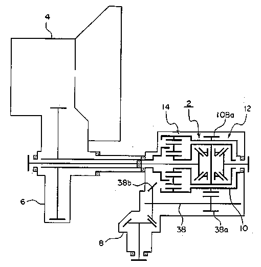
The Figure illustrates two differentials (12) and (14) are interconnected with each other such that one of the outputs of a first differential (14) is connected to the input of second differential (12).
This place covers:
Differentials having cams, for example, in between the two output members.
Illustrative example of subject matter classified in this place:
1a.

1b.

Figures 1a and 1b illustrate a differential without orbital gearing comprising cam groove (31) and balls (15) interacting between differential output members (12B) and (13B).
This place covers:
Differentials that divide one input into two outputs without using planet gears but by using two linked clutches.
Illustrative example of subject matter classified in this place:
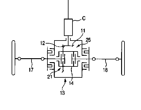
The Figure illustrates a differential (13) includes clutches (21, 25) which are used to provide differential rotary motion between output members (17) and (18).
Attention is drawn to the following places, which may be of interest for search:
Clutches |
Attention is drawn to the following places, which may be of interest for search:
Clutches |
This place covers:
Illustrative example of subject matter classified in this place:

The Figure illustrates a differential gearing (207) includes viscous coupling (211) and multi-plate friction clutch (215). Both the viscous coupling (211) and the multi-plate friction clutch (215) are used to limit differential action between the differential outputs (233) and (237).
This place covers:
Differentials, the differential action of which is suppressed by fluid pressure that is generated, for example, by internal pumps actuated by the difference of rotation numbers between two outputs.
Illustrative examples of subject matter classified in this place:
1a.
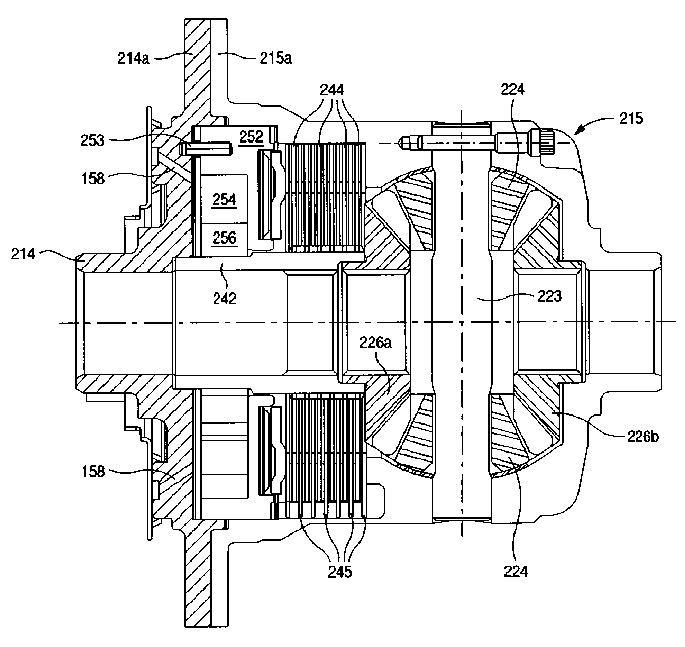
1b.

Figures 1a and 1b illustrate a differential (215) including a multi-plate friction clutch (244, 245) and a mechanical pump (252, 254, 256). The pump (252, 254, 256) actuates a piston to compress the multi-plate friction clutch (244, 245) in order to limit the differential action of the differential outputs (226a) and (226b).
This place covers:
Differentials, the differential action of which is suppressed in response to a difference in torque that is generated between two outputs. The differential action is suppressed using self-locking or self-braking gears.
This place covers:
Differentials, the differential action of which is suppressed by, for example, meshing reaction forces of helical gears that are arranged in parallel axes, by way of the said helical gears being pushed against the casing of the differentials.
Illustrative examples of subject matter classified in this place:
1a.

1b.
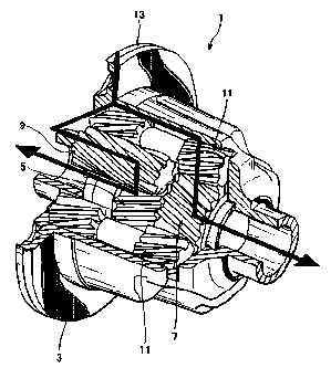
Figures 1a and 1b illustrate a differential (1) including helical orbital gears (9) and (11) intermeshing with parallel helical side gears (5) and (7). When a thrust force occurs in direction A, side gears (5) and (7) are pushed against housing (3) through thrust bearings (39) and (41), which suppresses differential action between side gears (5) and (7).
This place covers:
Differentials, the differential action of which is suppressed by, for example, meshing reaction forces of helical gears or worms that are arranged in orthogonal axes, by way of the said helical gears or worms being pushed against the casing of the differentials.
Illustrative example of subject matter classified in this place:

The Figure illustrates a differential (10) including worm gears (24) and (26) intermeshing with perpendicular helical side gears (20) and (22). When thrust forces (34, 36) occur, side gears (20) and (22) are pushed against housing (12) through washer (48) and spring (54), which suppresses differential action between side gears (20) and (22).
This place covers:
Differentials, in which the engaging power of a pilot clutch is amplified by using a cam, for example, and thereby, to have a main clutch engaged.
Illustrative example of subject matter classified in this place:

The Figure illustrates a differential (1) including orbital gears (23) intermeshing with bevel side gears (11) and (13). Differential (1) further includes main clutch (39), pilot clutch (33), and cam mechanism (35) for suppressing differential action. Cam mechanism (35) amplifies the engagement force of pilot clutch (33), which amplifies the engagement force of main clutch (39) via intermediate pressure member (65).
This place covers:
Differentials, the differential action of which is suppressed by, for example, fluidic actuators that are controllable from outside of the differential.
Illustrative example of subject matter classified in this place:
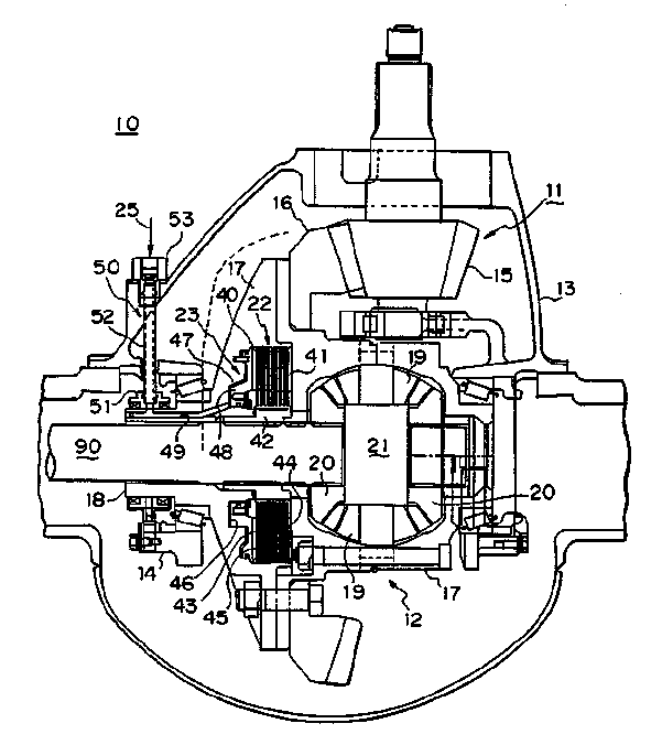
The Figure illustrates a differential (10) including bevel differential gearing (12), multi-plate friction clutch (22), and fluid pressure actuator (23). Fluid pressure actuator (23) actuates multi-plate friction clutch (22) in order to suppress differential action of the differential outputs (20).
This place covers:
Those differentials that are intentionally made to have different rotation numbers between two outputs for the purpose of improving the turning performance or controlling the yaw motion of vehicles.
Illustrative example of subject matter classified in this place:
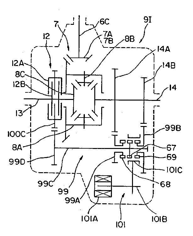
The Figure illustrates a differential (9I) including differential bevel gearing (7), clutch (12) and speed change mechanism (101). Speed change mechanisms (101) is used to change the speed of differential output (14), which generates a speed difference between differential outputs (13) and (14).
Attention is drawn to the following places, which may be of interest for search:
Arrangement or mounting of control means for varying left-right torque distribution in differential gearing, e.g. torque vectoring |
This place covers:
Those differentials that are characterised by such component parts as gear wheels, casings, washers, shafts, bearings or carriers
This place does not cover:
The outer casing comprising the differential and supporting input and output shafts |
This place covers:
Casings that accommodate the differential mechanism internally and are rotated by the power from the input shaft.
Illustrative example of subject matter classified in this place:
1a.
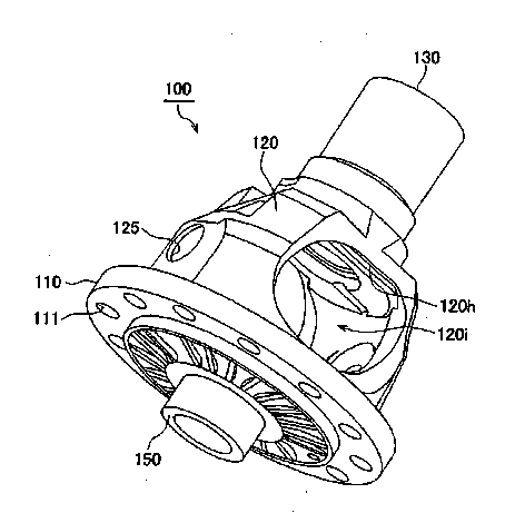
1b.

Figures 1a and 1b illustrate a differential (100) includes rotating differential case (120) having constructional cut-outs (120i).
This place covers:
Gearings or mechanisms not otherwise provided for:
- Wave gearings using flexible deformable members, e.g. Harmonic drive transmissions
- Magnetic gearings having in additional engaging gear elements, e.g. teeth
- Gearings using guided balls to transmit motion
Examples of places where the subject matter of this place is covered when specially adapted, used for a particular purpose, or incorporated in a larger system:
Harmonic drives for manipulators or robots |
Attention is drawn to the following places, which may be of interest for search:
Worm gears with balls between the cooperating gear parts | |
Gearings where the central axis of the gearing lies inside the periphery of an orbital gear | |
Gearings for conveying rotary motion with intermediate members guided along tracks on both rotary members | |
Rotating torque transmitting elements of the permanent-magnet type |
This place covers:
Illustrative examples of subject matter classified in this place:
1.

Figure 1 illustrates a wave gearing (1) including a cup-shaped flexspline (3).
2.

Figure 2 illustrates a wave gearing including flexspline (3) meshing with two ring gears (4) and (5).
Examples of places where the subject matter of this place is covered when specially adapted, used for a particular purpose, or incorporated in a larger system:
Harmonic drives for positioning means in programme-controlled manipulators | |
Harmonic drive of flexspline type in valve-gear arrangements of machines or engines |
Attention is drawn to the following places, which may be of interest for search:
Gearings comprising primarily only cams, cam-followers and screw-and-nut mechanisms for conveying rotary motion with intermediate members guided along tracks on both rotary members | |
Gearings comprising primarily only cams, cam-followers and screw-and-nut mechanisms for conveying rotary motion with intermediate members guided along tracks on both rotary members, the intermediate members being rollers supported in a chain | |
Profiling of flexible toothed member, e.g. harmonic drive |
In patent documents, the following words/expressions are often used as synonyms:
- "Strain wave", "wave generator", "flexspline", "flexible spline" and "circular spline"
Attention is drawn to the following places, which may be of interest for search:
Magnetic gearings, i.e. assembly of gears, linear or rotary, by which motion is magnetically transferred without physical contact | |
Dynamo-electric gears, i.e. dynamo-electric means for transmitting mechanical power from a driving shaft to a driven shaft and comprising structurally interrelated motor and generator parts |
This place covers:
Levers for gearing mechanisms.
Attention is drawn to the following places, which may be of interest for search:
Transmissions with cams | |
Gear levers for transmission control | |
Shafts, Bowden mechanisms, cranks, eccentrics, bearings, pivotal connections, crossheads, connection-rods | |
Manipulating levers |
The particular levers are also classified with the mechanism in which they are used.
This place covers:
Cams, camshafts or cam followers.
Examples of places where the subject matter of this place is covered when specially adapted, used for a particular purpose, or incorporated in a larger system:
Cams specially adapted for reciprocating-piston liquid engines |
Attention is drawn to the following places, which may be of interest for search:
Gearings comprising primarily only cams or cam-followers | |
Shafts, Bowden mechanisms, cranks, eccentrics, bearings, pivotal connections, crossheads, connection-rods |
This place covers:
- Constructional features of camshafts;
- Assembling or manufacturing of camshafts.
Examples of places where the subject matter of this place is covered when specially adapted, used for a particular purpose, or incorporated in a larger system:
Camshafts for valve gears |
Attention is drawn to the following places, which may be of interest for search:
Making crankshafts by working or processing metal tubes, rods or profiles without essentially removing material | |
Single-purpose machines for grinding of cams or camshafts |
This place covers:
- Different kind of gear elements for conveying rotary motion with and without teeth, e.g. gears, racks, worms, pulleys or chain wheels;
- Constructional features of these elements;
- Profiles of teeth for gearings.
This place does not cover:
Of screw-and-nut gearing |
This place covers:
- Use of materials for toothed gear members;
- Toothed gear members characterised by their material properties achieved by particular treatments;
- Gear features related to production by moulding, e.g. injection moulding.
Attention is drawn to the following places, which may be of interest for search:
Materials or coatings for screws or nuts | |
Coatings for lubrication | |
Making gear wheels by working or processing of sheet metal or metal tubes, rods or profiles without essentially removing material; Punching | |
Making metal gear wheels, racks, spline shafts or worms by rolling | |
Making forged or pressed wheels with gear-teeth | |
Making gears or toothed racks | |
Making metal gear parts, e.g. gear wheels, by operations not covered elsewhere | |
Producing gear wheels from plastics or substances in a plastic state | |
Gear wheels or similar articles with grooves or projections produced by shaping or joining of plastics | |
Heat treatment for gear wheels, worm wheels or the like | |
Processes for the electrolytic or electrophoretic production of coatings | |
Heating by electromagnetic field |
Attention is drawn to the following places, which may be of interest for search:
Measuring arrangements for measuring contours or curvatures of gears |
Examples of places where the subject matter of this place is covered when specially adapted, used for a particular purpose, or incorporated in a larger system:
Gearworks for clocks and watches |
Attention is drawn to the following places, which may be of interest for search:
Worm gear transmissions with balls between the cooperating gear elements |
This place does not cover:
Toothed gear wheels using particular materials for providing resilience or vibration damping |
Attention is drawn to the following places, which may be of interest for search:
Devices for varying tension of belts, ropes or chains with vibration damping means | |
Vibration-damping or noise reducing means specially adapted for gearings | |
Reducing vibrations or noise of the gearbox casing | |
Suppression of vibrations or noise of gear selectors or gear levers | |
Control of hydrostatic fluid gearing preventing or reducing vibrations or noise | |
Resilient coupling of wheel or wheel-rim with the shaft |
This place covers:
- Toothed wheels;
- Toothed belt pulleys.
This place does not cover:
Worm wheels | |
Chain wheels or sprockets |
Wheels having constructively simple tooth shapes, e.g. pins or balls, are additionally classified in F16H 55/10.
The use of material is additionally classified in F16H 55/06. In particular, moulded gears are additionally classified in F16H 2055/065.
This place covers:
- Means for taking up backlash when related to the toothed wheels. If backlash is taken up by modification of the shaft support, e.g. distance of axes between engaging members it should be classified in F16H 57/12.
- For bevel gears.
This place does not cover:
Arrangements for adjusting or for taking-up backlash for planetary gearings conveying rotary motion |
Attention is drawn to the following places, which may be of interest for search:
Arrangements for adjusting or for taking-up backlash by modification of axle distance |
Means for taking up backlash at worm wheels are classified in F16H 55/24.
Means for taking up backlash at racks are classified in F16H 55/28.
This place covers:
- Worm gears or worm wheels.
- Special features of worm gears.
Attention is drawn to the following places, which may be of interest for search:
Profiles of gears with perpendicular non-intersecting shaft arrangement | |
Bevel gears, crown wheels helical gears |
This place covers:
Worm gears or worm wheels with means for taking up backlash.
Attention is drawn to the following places, which may be of interest for search:
Transmission with arrangements for dividing torque between two or more worm wheels | |
Backlash reducing means for bevel gears, crown wheels or helical gears | |
Means for taking up backlash at racks | |
Support of worm gear shafts | |
Arrangements for adjusting or for taking-up backlash not provided for elsewhere |
This place covers:
Pressure yokes for biasing racks against pinion gears in order to take up backlash.
Illustrative example of subject matter classified in this place:

The Figure illustrates a rack and pinion gearing including a rack (16a) which is biased against a pinion gear (20a) using a pressure yoke (100) and a spring (102).
Examples of places where the subject matter of this place is covered when specially adapted, used for a particular purpose, or incorporated in a larger system:
Steering gears of rack-and-pinion type characterised by pressure yokes |
This place covers:
Pressure yokes with rollers or ball to reduce friction, for biasing racks against pinion gears in order to take up backlash.
Illustrative examples of subject matter classified in this place:
1a.

1b.

Figures 1a and 1b illustrate an example of a rack and pinion gearing including a rack (2) which is biased against pinion (6) using a pressure yoke (8) and spring (25). Balls (19) reduce friction on rack (2).
2.

Figure 2 illustrates a rack and pinion gearing including a rack (4) which is biased against a pinion gear (2) by a pressure yoke (5) and a spring (7). Roller bearings (9) reduce friction on rack (4).
This place covers:
Pressure yokes with asymmetric layout of the yoke, for biasing racks against pinion gears in order to take up backlash.
Illustrative examples of subject matter classified in this place:
1.

Figure 1 illustrates a rack and pinion gearing including a rack (1') which is biased against a pinion gear (3') using an asymmetric yoke (7') and a spring (9').
2.

Figure 2 illustrates a rack and pinion gearing including a rack (29) which is biased against a pinion gear (28) using an asymmetric yoke (31) and a spring (33).
This place covers:
Two or more pressure yokes, for biasing racks against pinion gears in order to take up backlash.
Illustrative examples of subject matter classified in this place:
1.

Figure 1 illustrates a rack and pinion gearing including a rack (120) which is biased against a pinion gear (111) using two yokes (170) and respective springs (160).
2.

Figure 2 illustrates a rack and pinion gearing including a rack (41) which is biased against a pinion gear using two yokes (25) and respective springs (39).
Examples of places where the subject matter of this place is covered when specially adapted, used for a particular purpose, or incorporated in a larger system:
Chain wheels specially adapted for cycles |
Attention is drawn to the following places, which may be of interest for search:
Friction surfaces |
Attention is drawn to the following places, which may be of interest for search:
Means or measures for increasing adhesion in general |
This place does not cover:
Means or measures for increasing adhesion of pulleys | |
Laminated pulleys | |
Split pulleys |
Attention is drawn to the following places, which may be of interest for search:
Manufacture of wood-rimmed wheels, e.g. cart wheels, steering wheels |
This place covers:
Pulleys or friction discs where the diameter of the pulley or friction disc can be modified in order to adjust the placement of the flexible member.
Attention is drawn to the following places, which may be of interest for search:
Control of continuously variable gearing with endless flexible members | |
A single final output mechanism having an indefinite number of positions and being moved by a single final actuating mechanism |
This place covers:
Pulleys or friction discs with axially adjustable bearing parts and centrifugal masses for automatically changing the active diameter of the pulley or friction disc dependent on speed.
This place covers:
- Monitoring wear or stress of transmission elements;
- Gearboxes, mounting gearing therein;
- Features related to lubrication or cooling;
- General details of gearings with members having orbital motion;
- Arrangement for adjusting or taking-up backlash not provided for elsewhere.
This place does not cover:
General details of screw-and-nut gearing | |
General details of fluid gearing |
This place does not cover:
Belt tension means with vibration damping means | |
Construction of toothed members providing resilience or vibration-damping | |
Gearboxes characterised by means for reducing vibration or noise | |
Selector apparatus with means for suppression of vibrations or reduction of noise | |
Preventing or reducing vibrations or noise, e.g. avoiding cavitations, in control of hydrostatic gearing |
Attention is drawn to the following places, which may be of interest for search:
Gears having orbital motion with arrangements for adjusting or taking-up backlash | |
Idle pulley for belt tension means with vibration damping means | |
Screw mechanisms with arrangements for adjusting or taking-up backlash | |
Screw mechanisms with balls with arrangements for adjusting or taking-up backlash | |
Silent gear profiles of toothed members and worms | |
Toothed wheels with special devices for taking up backlash | |
Worms and worm gears with special devices for taking up backlash | |
Racks with special devices for taking up backlash | |
Means for providing resilience or vibration damping in chain sprocket wheels | |
Pulleys with means for providing resilience or vibration damping | |
Arrangements for adjusting or taking-up backlash not provided elsewhere |
Attention is drawn to the following places, which may be of interest for search:
Shaft support structures with adjustment of gear shafts or bearings |
Attention is drawn to the following places, which may be of interest for search:
Toothed wheels specially adapted for easy repair |
Attention is drawn to the following places, which may be of interest for search:
Modifying an existing transmission control from a manufacturer for improvement or adaptation, e.g. by replacing a valve or an electric part |
Attention is drawn to the following places, which may be of interest for search:
Detection of mechanical transmission failures |
Attention is drawn to the following places, which may be of interest for search:
Computer-aided design [CAD] per se |
This place covers:
Devices attached to the gearbox or gearing for:
- informing of the end-of-life cycle;
- informing of the timing for triggering maintenance or parts replacement;
- monitoring wear or stress of gearing elements.
Attention is drawn to the following places, which may be of interest for search:
Testing of gearing or of transmission mechanisms |
Attention is drawn to the following places, which may be of interest for search:
Arrangements for monitoring working conditions, e.g. wear, temperature, of clutches |
Attention is drawn to the following places, which may be of interest for search:
Monitoring of overload conditions of gearing elements |
Attention is drawn to the following places, which may be of interest for search:
Fixing of, or adapting to, transmission failure | |
Detecting malfunction or potential malfunction for transmission control |
Attention is drawn to the following places, which may be of interest for search:
Actuator casings for screw mechanisms |
This place covers:
Gears mounted in the gearbox by positioning them relative to one another by rolling members or by specially adapted surfaces on the gears, e.g. by a rolling surface with the diameter of the pitch circle.
Illustrative examples of subject matter classified in this place:
1.

Figure 1 illustrates a pair of toothed spur gears (1) and (2) positioned relative to each other using left and right thrust collars attached to the surface of gear (2). The thrust collars are regarded as comprising specially adapted surfaces on the gears by which the two spur gears are positioned relative to one another.
2.

Figure 2 illustrates a pair of toothed spur gears (1) and (2) positioned relative to each other. Spur gear (1) has projections (5) between its teeth which interact with grooves 6 between the teeth of spur gear (2). Projections (5) and grooves (6) are regarded as comprising specially adapted surfaces on the gears by which the two spur gears are positioned relative to one another.
3.

Figure 3 illustrates a pair of toothed spur gears (62) and (72) positioned relative to one another using rolling members (64) and (74). Due to bearing (66), rolling members (64) and (74) do not transfer any torque and maintain alignment of the gears.
In patent documents, the following words/expressions are often used as synonyms:
- "Thrust cam" and "thrust collar"
- (German) "Druckkamm", (German) "Druckkammgetriebe" and (German) "Druckkämme"
This place covers:
Illustrative example of subject matter classified in this place:

The Figure illustrates housing components (27), (28) and (38) are welded together to form a common housing that houses both the crank of the engine and the belt-type CVT.
Attention is drawn to the following places, which may be of interest for search:
Combinations of engines with mechanical gearing |
Attention is drawn to the following places, which may be of interest for search:
Structural association of gears with electric machines |
Attention is drawn to the following places, which may be of interest for search:
Transmission of mechanical power in wind motors | |
Transmission of power in wind motors |
Attention is drawn to the following places, which may be of interest for search:
Using particular materials for reducing weight of gearbox |
Attention is drawn to the following places, which may be of interest for search:
Shafts; Bearings |
This place does not cover:
Attention is drawn to the following places, which may be of interest for search:
Gears having orbital motion with arrangements for adjusting or taking-up backlash | |
Supports for screw mechanisms for compensating misalignment or offset between screw and nut | |
Support of worm gear shafts in gearboxes | |
Arrangements for adjusting or taking-up backlash not provided elsewhere | |
Gears specially adapted for positioning means of programme-controlled manipulators with backlash-preventing means |
This place covers:
Methods and procedures for mounting or installing gearing elements or shafts in gearboxes.
Methods for mounting or installing gearing elements by using tools, e.g. guide members, jigs or the like.
Attention is drawn to the following places, which may be of interest for search:
Repairing of transmissions by using repair kits |
This place covers:
Means for supporting gearboxes or attaching them to other devices in order to prevent the casing from being moved due to reaction forces or torques produced by the gearing, e.g. torque arms.
Illustrative example of subject matter classified in this place:
Examples of places where the subject matter of this place is covered when specially adapted, used for a particular purpose, or incorporated in a larger system:
Mounting of transmissions in vehicles |
This place covers:
Gearboxes characterised by means for preventing escape of liquids (e.g. lubrication oil) or gases.
Gearboxes characterised by means for preventing ingress of liquids, gases, dust or the like.
Attention is drawn to the following places, which may be of interest for search:
Lubrication storage reservoirs with sealings between different partitions of gearing or to a reservoir | |
Sealings |
This place covers:
A group of similar gearboxes based on the same design, e.g. being available in different sizes.
A group of gearboxes which comprises a combination of several standardised units and which can meet various requirements by altering the combination of such units.
Illustrative example of subject matter classified in this place:
This place covers:
Housing components of gearboxes for accommodating differential gearings, which housing components are usually not intended to revolve with the differential gearings, e.g. housing (1) in the illustration below.
Illustrative example of subject matter classified in this place:

This place does not cover:
Rotating cases for differential gearings |
Attention is drawn to the following places, which may be of interest for search:
Differential gearings |
This place does not cover:
Gearboxes for accommodating differential gearings |
Attention is drawn to the following places, which may be of interest for search:
Toothed gearings comprising worm and worm-wheel |
This place covers:
Lubrication or cooling of gearings.
This place does not cover:
Control of lubrication or cooling in hydrostatic gearing |
Attention is drawn to the following places, which may be of interest for search:
Lubrication systems in vehicles | |
Vehicle endless-track units with lubrication means | |
Lubricating of machines and engines in general | |
Lubrication in general |
Attention is drawn to the following places, which may be of interest for search:
Sealings between different partitions of a gear case or reservoir |
Attention is drawn to the following places, which may be of interest for search:
Venting trapped air for hydraulic systems | |
Venting of hydraulic transmissions | |
Filtration, Filtering material | |
Degasification of liquids | |
Deaeration of lubricants |
This place covers:
Filter devices.
Magnets for collecting metallic debris.
Attention is drawn to the following places, which may be of interest for search:
Oilsumps with filter |
Attention is drawn to the following places, which may be of interest for search:
Investigating or analysing lubricating oil characteristics, e.g. deterioration, by specific methods | |
Investigating or analysing lubricating properties of oils by specific methods |
This place covers:
- Feeding lubricant by a felt or other foamed material. The felt often forms a reservoir for life time lubrication.
- Feed by capillary action, e.g. using a wick.
Attention is drawn to the following places, which may be of interest for search:
Grease depots |
This place covers:
- Draining of transmission fluids;
- Filling of transmission fluids;
- Exchange of transmission fluids, e.g. fluids for automatic transmissions;
- Cleaning or flushing of transmissions.
Examples of places where the subject matter of this place is covered when specially adapted, used for a particular purpose, or incorporated in a larger system:
Servicing, maintaining, repairing, or refitting of vehicles | |
Filling or draining lubricant of or from machines or engines |
Attention is drawn to the following places, which may be of interest for search:
Flushing in hydrostatic fluid gearing |
Attention is drawn to the following places, which may be of interest for search:
Use of materials for toothed members | |
Bearings with solids as lubricant, e.g. dry coatings, powder |
This place covers:
Cooling or heating of the transmission, its elements, e.g. gears, casings or of the lubricant.
Attention is drawn to the following places, which may be of interest for search:
Arrangement or mounting of electrical propulsion units with means for cooling the electric propulsion units | |
Arrangement in connection with cooling of propulsion units | |
Controlling the temperature of batteries | |
Cooling of machines and engines in general | |
Cooling circuits not specific to a single part of engine or machine | |
Controlling of coolant flow in engines or machines | |
Engine or machine cooling circuit using a lubricant cooler for transmissions | |
Features relating to cooling in friction clutches | |
Details of fluid actuated clutches in view of cooling and lubrication | |
Hydraulic circuits combining clutch actuation with clutch lubrication or cooling | |
Oil or fluid cooling of clutches or couplings | |
Arrangements for cooling or ventilating electric machines |
Attention is drawn to the following places, which may be of interest for search:
Heat exchangers per se |
This place covers:
The term "air cooling or ventilation" shall include transmission elements and/or lubricants cooled by heat exchange with ambient air, e.g. ventilated air cooling of CVT belts, guidance of lubricant through air cooled tubes or air cooled parts of the casing, cooling fins inside or outside the casing.
This place covers:
The "heat exchangers" shall include lubricant cooled or heated by heat exchange with another fluid, e.g. with water, oil or exhaust gas.
Attention is drawn to the following places, which may be of interest for search:
Heat exchangers per se |
Attention is drawn to the following places, which may be of interest for search:
Means for guiding lubricant into an axial channel of a shaft | |
Lubrication by injection; Injection nozzles or tubes therefor |
Attention is drawn to the following places, which may be of interest for search:
Means for guiding lubricant into an axial channel of a shaft |
Attention is drawn to the following places, which may be of interest for search:
Lubrication, cooling, or heating of shift rods or shift forks |
This place covers:
All kinds of lubrication pumps for gearing or special means to produce flow of lubrication in gearing. Also, lubrication control units or valves to supply the transmission with lubricant.
Attention is drawn to the following places, which may be of interest for search:
Grooves on rotary parts with pumping effect for supplying lubricant | |
Generation or control of line pressure |
Attention is drawn to the following places, which may be of interest for search:
Arrangement of lubrication pumps | |
Supply of control fluid; Pumps or accumulators therefor | |
Gear pumps per se | |
Vane pumps per se | |
Lubrication of pumps per se | |
Lubricating pumps per se |
This place covers:
The term "gearbox section" means a section containing gearing elements like gear, belts, chains or clutches. A section comprising only shaft support bearings is not considered as a different gearbox section.
Attention is drawn to the following places, which may be of interest for search:
Control of lubricant levels | |
Section walls to divide a gear sump |
Attention is drawn to the following places, which may be of interest for search:
Generation or control of line pressure characterised by controlled fluid supply to lubrication circuits of the gearing |
Attention is drawn to the following places, which may be of interest for search:
Exchange, draining or filling of transmission lubricant | |
Splash lubrication |
F16H 57/0447 should not be allocated to documents which merely disclose a splash lubrication. The lubricant level of any splash lubrication sump depends on the rotational speed of the splashing element, but, if a document does not explicitly disclose the problem of "level control", classification should be given only in group F16H 57/0457 for "splash lubrication".
F16H 57/0447 shall also not be allocated to documents dealing with "providing a correct fill level". These are classified in F16H 57/0408 "exchange or filling of transmission lubricant".
Attention is drawn to the following places, which may be of interest for search:
Indicating or measuring liquid level |
Attention is drawn to the following places, which may be of interest for search:
Lubrication supply or pressure control for different gearbox casings or sections |
Group F16H 57/045 "lubricant storage reservoir" is essentially given for "additional reservoirs" or for non-trivial disclosure of gear sumps. It shall not be given for the mere disclosure of a gear sump.
This place covers:
Splash lubrication, e.g. by gearing elements plunging into an oil bath.
Attention is drawn to the following places, which may be of interest for search:
Characterised by increasing efficiency, e.g. by reducing splash losses | |
Control of lubricant levels |
Attention is drawn to the following places, which may be of interest for search:
Gearboxes characterised by means for venting gearboxes, e.g. air breathers |
This place covers:
- Grease lubrication.
- Grease depots.
- Drip lubrications.
Attention is drawn to the following places, which may be of interest for search:
Arrangements for supplying grease from a stationary reservoir or equivalent |
Attention is drawn to the following places, which may be of interest for search:
Lubrication guiding means on or inside shift rods or shift forks | |
Gear shift yokes |
Attention is drawn to the following places, which may be of interest for search:
Gearboxes associated or combined with the crankcase of the engine | |
Controlled cooling or heating of lubricant; Temperature control therefor | |
Joint lubrication or cooling of electric machines and gearing | |
Arrangement in connection with cooling of propulsion units | |
Lubricating of machines and engines in general; Lubricating internal combustion engines; Crankcase ventilating | |
Cooling of machines and engines in general | |
Engine or machine cooling circuit using a lubricant cooler for transmissions |
In case of controlled cooling or heating of lubricant, classification should also be given in group F16H 57/0413.
Attention is drawn to the following places, which may be of interest for search:
Gearboxes combined or associated with electric machines | |
Controlled cooling or heating of lubricant; Temperature control therefor | |
Joint lubrication or cooling of engine and gearing | |
Arrangement or mounting of electrical propulsion units with means for cooling the electric propulsion units | |
Arrangement in connection with cooling of propulsion units | |
Controlling the temperature of batteries | |
Electric machines with channels or ducts for flow of cooling medium in stationary parts of the magnetic circuit | |
Electric machines with channels or ducts for flow of cooling medium in rotating parts of the magnetic circuit | |
Electric machines with channels or ducts for flow of cooling medium in casings | |
Arrangements for cooling or ventilating electric machines |
In case of controlled cooling or heating of lubricant, classification should also be given in group F16H 57/0413.
For classification in subgroups of F16H 57/04, if there is no particular application place for the type of gearing in the subgroups of F16H 57/048 - F16H 57/0498, a group outside F16H 57/04 should be given at least as "additional information" in order to identify the type of gearing being lubricated, cooled or heated. For example, in a case of lubrication of wobble plate gears, a group in F16H 23/00 should be given at least as "additional information".
Examples of places where the subject matter of this place is covered when specially adapted, used for a particular purpose, or incorporated in a larger system:
Features relating to lubrication or cooling of chains for conveyors |
This place covers:
Bearings of orbital gears, i.e. sliding and/or rolling contact bearings supporting orbital gears on the carrier.
Illustrative example of subject matter classified in this place:
1a.

Figure 1a illustrates a planet carrier (2) and planet gear (6), including a needle bearing (5) as a rolling contact bearing, and left and right thrust washers (8) as sliding contact bearings which support the planet gear (6) on a planet pin (4) of the planet carrier (2).
1b.

Attention is drawn to the following places, which may be of interest for search:
Toothed gearing using gears having orbital motion for conveying rotary motion with variable gear ratio or for reversing rotary motion | |
Constructional features of final output mechanisms comprising friction clutches or brakes | |
Constructional features of final output elements, i.e. the final elements to establish gear ratio, e.g. coupling sleeves or other means establishing coupling to shaft |
Examples of places where the subject matter of this place is covered when specially adapted, used for a particular purpose, or incorporated in a larger system:
Gears specially adapted for positioning of programme-controlled manipulators with backlash-preventing means |
Attention is drawn to the following places, which may be of interest for search:
Gears having orbital motion with arrangements for adjusting or taking-up backlash | |
Screw mechanisms with arrangements for taking up backlash | |
Screw mechanisms with balls with arrangements for taking up backlash | |
Toothed wheels with special devices for taking up backlash | |
Worms or worm gears with special devices for taking up backlash | |
Racks with special devices for taking up backlash | |
Support of worm gear shafts in gearboxes | |
Adjustment of transmission shafts or bearings in gearboxes |
This place covers:
- Detecting or using driving style of a driver, e.g. for adapting shift schedules;
- Overriding automatic control;
- Selector apparatus, e.g. gear shift or range levers;
- Control inputs being a function of different parameters, e.g. torque, speed, transmission status, road condition, load, steering, clutch, or engine.
Examples of places where the subject matter of this place is covered when specially adapted, used for a particular purpose, or incorporated in a larger system:
Attention is drawn to the following places, which may be of interest for search:
Final output mechanisms in the gearbox, e.g. selector or shifting means in the gearbox | |
Input parameters for road vehicle drive control systems not related to the control of a particular subunit |
The input values for the control system represent in most cases only 'additional information'. The input values for the control system are classified as 'invention information' only if the measuring device or the method for measuring the value forms an essential part of the invention.
In groups F16H 59/00 - F16H 63/00, clutches positioned within a gearbox are considered as comprising part of the gearings.
When classifying in groups F16H 59/00 - F16H 63/00, control inputs or types of gearing which are considered to represent information of interest for search, may also be classified. Such non-obligatory classification should be given as "additional information", e.g. selected from subgroup F16H 61/66 relating to the type of gearing controlled or from group F16H 59/00 relating to control inputs.
In this place, the following terms or expressions are used with the meaning indicated:
mechanism | a kinematic chain consisting either of a single element or alternatively of a series of elements, the position of each point on the kinematic chain being derivable from the position of any other point on the chain, and therefore, for a given position of a point on one of the elements forming the kinematic chain there is only one position for each of the other points on the element or series of elements forming the kinematic chain |
final output mechanism | the mechanism which includes the final output element, e.g. hydraulic or electromagnetic clutch, synchronizer clutch, ball and ramp clutch |
final output element | the final element which is moved to establish a gear ratio, i.e. which achieves the linking or coupling between two power transmission means, e.g. reverse idler gear, gear cluster, coupling sleeve, apply piston of a hydraulic clutch |
actuating mechanism | the mechanism, the movement of which causes the movement of another mechanism by being in mutual contact |
final actuating mechanism | the mechanism actuating the final output mechanism, i.e. this mechanism actuates the final output mechanism which includes the final output element, e.g. coupling sleeve, shift fork, hydraulic circuit, electromagnetic solenoid, motor |
Attention is drawn to the following places, which may be of interest for search:
Control devices or systems insofar as characterised by mechanical features only |
Attention is drawn to the following places, which may be of interest for search:
Ratio selector apparatus consisting of electrical switches or sensors | |
Range selector apparatus comprising levers and consisting of electrical switches or sensors |
Attention is drawn to the following places, which may be of interest for search:
Range selector apparatus for different transmission modes | |
Selecting between different operative modes in road vehicle drive control systems not related to the control of a particular subunit |
Attention is drawn to the following places, which may be of interest for search:
Voice control of electric circuits specially adapted for vehicles |
Attention is drawn to the following places, which may be of interest for search:
Multiple final output mechanisms being moved by a single common final actuating mechanism, the final output mechanisms being successively actuated by progressive movement of the final actuating mechanism |
Attention is drawn to the following places, which may be of interest for search:
Range selector apparatus comprising push button devices |
Attention is drawn to the following places, which may be of interest for search:
Ratio selector apparatus comprising a final actuating mechanism |
Attention is drawn to the following places, which may be of interest for search:
Final output mechanisms and actuating means for the final output mechanisms |
Attention is drawn to the following places, which may be of interest for search:
Final output mechanisms and actuating means for the final output mechanisms |
Attention is drawn to the following places, which may be of interest for search:
Range selector apparatus comprising levers and consisting of electrical switches or sensors |
Attention is drawn to the following places, which may be of interest for search:
Up- and down-shift or range or mode selection by repeated movement |
Attention is drawn to the following places, which may be of interest for search:
Constructional features of selector lever handles with lock mechanisms |
Attention is drawn to the following places, which may be of interest for search:
Inputs being a function of pump torque in hydrostatic transmissions | |
Inputs being a function of motor torque in hydrostatic transmissions |
Attention is drawn to the following places, which may be of interest for search:
Idle position |
Attention is drawn to the following places, which may be of interest for search:
Coasting |
Attention is drawn to the following places, which may be of interest for search:
Inputs being a function of pump speed in hydrostatic transmissions | |
Inputs being a function of motor speed in hydrostatic transmissions |
This place covers:
Input being a function of the detected vehicle travel direction, and the detected travel direction is based on vehicle speed.
Attention is drawn to the following places, which may be of interest for search:
Inputs being a function of rate of change of input shaft speed, e.g. of engine or motor shaft | |
Inputs being a function of rate of change of gearing output shaft speed or vehicle speed | |
Inputs being a function of rate of change of gearing input or turbine shaft speed |
Attention is drawn to the following places, which may be of interest for search:
Input as a function of sensed pressures in hydrostatic transmissions |
Attention is drawn to the following places, which may be of interest for search:
Input as a function of transmission input torque |
Examples of places where the subject matter of this place is covered when specially adapted, used for a particular purpose, or incorporated in a larger system:
F16H 61/04 is used for the more general aspects of gear shifting, since there is no proper place in IPC for gear shifting per se. In other words, the gear smooth effect is not an essential feature for classification in F16H 61/04.
This place covers:
- Arrangements of the control unit on or in the transmission gearbox.
- General features of the control units, e.g. supporting or connection of printed circuits, channel plates for supporting valves.
- Arrangement or mounting of elements of the control apparatus, e.g. valve assemblies or snap-fittings of valves.
Attention is drawn to the following places, which may be of interest for search:
Housings for electric apparatus for protecting electronics against vibration or moisture |
This place covers:
Pumps and control circuits for generating or controlling line pressure for transmission control.
Attention is drawn to the following places, which may be of interest for search:
Layout of electro-hydraulic control circuits for gearshift control | |
Layout of hydraulic control circuits for gearshift control | |
Generation or transmission of movements for final actuating mechanisms with at least one movement of the final actuating mechanism being caused by a non-mechanical force using electric control signals for shift actuators | |
Generation or transmission of movements for final actuating mechanisms with at least one movement of the final actuating mechanism being caused by a hydraulic motor | |
Control for optimising pump efficiency in CVTs with endless flexible members |
This place covers:
Supply of control fluid, e.g. fluid pumps or accumulators for generating line pressure.
This place covers:
Auxiliary pumps provided in addition to a main pump for supplying hydraulic fluid to the transmission control circuit, e.g. an auxiliary pump supplying hydraulic fluid when the engine has stopped.
This place covers:
Supply of lubrication of the transmission is taken from the hydraulic control supply.
Attention is drawn to the following places, which may be of interest for search:
Lubrication supply forming part of the transmission control unit |
Attention is drawn to the following places, which may be of interest for search:
Control of venting of hydrostatic transmissions | |
Removal or measurement of undissolved gas in general |
This place covers:
Gearings where braking is achieved by simultaneous engagement of two or more engaging means, e.g. clutches or brakes, which are applied for different gear ratios. This method of braking the transmission is sometimes used instead of a parking lock.
Attention is drawn to the following places, which may be of interest for search:
Providing engine brake control | |
Constructional features of parking lock mechanisms or brakes in the transmission | |
Signals to parking lock or parking brake |
Attention is drawn to the following places, which may be of interest for search:
Testing of gearings and transmission mechanisms |
This place covers:
Gearshift control units using specific types of shift signals.
Methods for generating shift signals, including:
- Estimating or calculating of optimal gears or ranges therefor;
- Generating or modifying shift maps;
- Selecting a particular map or ratio depending on particular conditions or situations.
Attention is drawn to the following places, which may be of interest for search:
Generation or transmission of movements for final actuating mechanisms with at least one movement of the final actuating mechanism being caused by a non-mechanical force | |
Control specially adapted for continuous variable gearings | |
Control specially adapted for stepped gearings without interruption of drive and with two inputs | |
Control specially adapted for change speed gearing in group arrangement |
Control units are classified according to their essential kind of signals as follows:
Control units where gearshift control is controlled by an electric signal, are classified in F16H 61/0202. This group includes electro-hydraulic circuits using different solenoids, which are classified in F16H 61/0206. A control unit with a single solenoid for a subfunction (e.g. kickdown) is not considered an electro-hydraulic control circuit in the sense of F16H 61/0206.
Control units where gearshift control is controlled by hydraulic signals, are classified in F16H 61/0262. Control units where gearshift is controlled by hydraulic signals and a subfunction (e.g. kickdown) is controlled by an electric circuit, are classified in F16H 61/0262.
Circuits where gearshift control is essentially controlled by purely mechanical forces, e.g. by using centrifugal or gear forces, are classified in F16H 61/0293.
Attention is drawn to the following places, which may be of interest for search:
Smoothing ratio shift |
Attention is drawn to the following places, which may be of interest for search:
Generation or transmission of movements for final actuating mechanisms with at least one movement of the final actuating mechanism being caused by a non-mechanical force using electric control signals for shift actuators |
Attention is drawn to the following places, which may be of interest for search:
Generation or transmission of movements for final actuating mechanisms with at least one movement of the final actuating mechanism being caused by a non-mechanical force |
Attention is drawn to the following places, which may be of interest for search:
Smoothing ratio shift |
Attention is drawn to the following places, which may be of interest for search:
Generation or transmission of movements for final actuating mechanisms with at least one movement of the final actuating mechanism being caused by hydraulic or pneumatic motors or related fluid control means |
Attention is drawn to the following places, which may be of interest for search:
Generation or transmission of movements for final actuating mechanisms with at least one movement of the final actuating mechanism being caused by a non-mechanical force |
This place covers:
Controlling the gearing in order to smooth the shift between ratios, e.g. to reduce shift shock.
Attention is drawn to the following places, which may be of interest for search:
Control outputs comprising signals to a clutch outside the gearbox | |
Control outputs comprising signals to an engine or motor for smoothing gear shifts |
F16H 61/04 is used for the more general aspects of gear shifting, since there is no proper place in IPC for gear shifting per se. In other words, the gear smooth effect is not an essential feature for classification in this area.
If there is pressure control between a releasing gear shift element and an engaging gear shift element, the document is classified in F16H 61/06.
Attention is drawn to the following places, which may be of interest for search:
Smoothing ratio shift by preventing or solving a tooth butt situation upon engagement failure due to misalignment of teeth |
Attention is drawn to the following places, which may be of interest for search:
Control of torque converter lock-up clutches using electric control means |
This place covers:
Control of fluid pressure for a releasing gear shift element or an engaging gear shift element for shift transition from a current ratio to a new target ratio.
This place covers:
Timing control during shift transition.
Some timing control is always performed during shifting. Therefore, only documents showing special inventive features related to timing control are covered by this group.
This place does not cover:
Detecting malfunction or potential malfunction in control of exclusively hydrostatic gearing |
Attention is drawn to the following places, which may be of interest for search:
Monitoring wear or stress of transmission elements, e.g. for triggering maintenance | |
Detection of mechanical transmission failures | |
Ensuring safety in case of control system failures, e.g. by diagnosing, circumventing or fixing failures, for control systems of road vehicle drive controls not related to control of a particular sub-unit |
Attention is drawn to the following places, which may be of interest for search:
Braking of gear output shaft using simultaneous engagement of engaging means, e.g. clutches or brakes, applied for different gear ratios |
Attention is drawn to the following places, which may be of interest for search:
Bringing the control into a predefined state using fail priority valves |
Attention is drawn to the following places, which may be of interest for search:
Smoothing ratio shift |
This place does not cover:
Preventing unintentional or unsafe shift |
Attention is drawn to the following places, which may be of interest for search:
Gearshift control characterised by the method for generating electric shift signals |
Classification in F16H 61/16 is related to unfavourable conditions and not to an unintentional control input by the driver. A device where the reverse gear is blocked because the vehicle speed is too high would be classified in F16H 61/16. A device for preventing unintended movements of a shift lever (e.g. a shift from fifth gear into reverse) is classified in F16H 61/18.
Attention is drawn to the following places, which may be of interest for search:
Constructional features of selector lever handles with lock mechanisms | |
Locking of the control input device | |
Constructional features of the final output mechanism |
Attention is drawn to the following places, which may be of interest for search:
Vehicle drive off | |
Preparing to drive off | |
Holding or hill holding | |
Creeping | |
Going to or coming from stand by operation, e.g. for engine start stop operation at traffic lights |
This place covers:
Reducing the engine speed by controlling the transmission.
This place covers:
Locking of a control device with the exception of final output mechanisms, e.g. locking of range lever in the 'Park' position.
This place does not cover:
Locking of the final output mechanisms |
Examples of places where the subject matter of this place is covered when specially adapted, used for a particular purpose, or incorporated in a larger system:
Vehicle fittings for preventing unauthorised use operating on the vehicle transmission, e.g. ignition keys interlocked with gear box or gear lever |
Attention is drawn to the following places, which may be of interest for search:
Emergency release or engagement of parking locks or brakes in the transmission |
This place covers:
- Actuators for moving final actuating mechanisms.
- Means for transmitting movement for selecting and shifting by cables.
- Linkages for transmitting movement essentially outside the gear box.
The generation or transmission of movements comprising essentially the selector apparatus, is classified in group F16H 59/00.
The generation or transmission of movements, when part of the final output mechanisms, is classified in group F16H 63/00.
This place covers:
- Fluid actuators moving the final actuating mechanism;
- Servo actuators moving the final actuating mechanism, e.g. for power assisted shifting;
- Electric actuators, e.g. actuators using electric motors or solenoids, moving the final actuating mechanism;
- Control of actuators for moving the final actuating mechanism.
Attention is drawn to the following places, which may be of interest for search:
Inputs being a function of the gearing status | |
Gearshift control characterised by the method for generating electric shift signals | |
Hydraulic actuators forming part of the final actuating mechanism | |
Electric actuators forming part of the final actuating mechanism |
This place does not cover:
Hydraulic or pneumatic motors or related fluid control means for generation or transmission of movements for final actuating mechanisms | |
Electric motors or actuators or related electrical control means for generation or transmission of movements for final actuating mechanisms |
Attention is drawn to the following places, which may be of interest for search:
Gearshift control characterised by the method for generating electric shift signals |
This place covers:
Fluid motors or actuators for moving final actuating mechanisms, e.g. hydraulic or pneumatic servo actuators, and their related control means.
Attention is drawn to the following places, which may be of interest for search:
Inputs being a function of the gearing status | |
Gearshift control characterised by the method for generating electric shift signals | |
Constructional features of final output mechanisms comprising elements moved by fluid pressure |
This place covers:
Electric motors or actuators for moving final actuating mechanisms, e.g. electric servo actuators, and their related control means.
Attention is drawn to the following places, which may be of interest for search:
Inputs being a function of the gearing status | |
Gearshift control characterised by the method for generating electric shift signals | |
Electric actuators forming part of the final actuating mechanism |
This place does not cover:
With at least one movement, e.g. for selecting or shifting, being transmitted by a cable |
Attention is drawn to the following places, which may be of interest for search:
Ratio selector apparatus comprising a final actuating mechanism | |
Final output mechanisms having elements remote from the gearbox |
Attention is drawn to the following places, which may be of interest for search:
Control of combinations of mechanical gearing with fluid clutches or fluid gearing |
This place covers:
- Devices or systems to vary the transmission ratio of hydrostatic gearing or control the hydraulic power transmission between a pump and a motor having no specific entry in the following subgroups.
- Arrangements or mountings of the control apparatus on the hydrostatic gearing.
Attention is drawn to the following places, which may be of interest for search:
Hydrostatic gearings comprising integrated control parts (valves) or accessories |
This place covers:
- Devices for controlling pressure not specific for the high or low working pressures.
- Control of differential pressure.
This place covers:
- Devices for limiting a maximum pressure in the hydrostatic high pressure conduits;
- Check valves, relief valves, regulating valves.
Attention is drawn to the following places, which may be of interest for search:
Preventing overload by changing the capacity of a pump or a motor |
This place covers:
- Devices for regulating or limiting pressure in the hydrostatic low pressure conduits.
- Check valves, relief valves, regulating valves in low pressure conduits.
This place covers:
- Devices for regulating the circuit flow.
- Pulsing stop valves, orifice valves or variable restrictions in the conduits.
This place covers:
- Devices for connecting high pressure conduits with low pressure conduits.
- Control circuits characterised by features related to the bypass valves.
This place covers:
- Devices for varying the bypass flow, e.g. for implementing a starting clutch of the hydrostatic transmission.
- Variable orifice valves.
This place covers:
- Devices for changing the rotational direction of the motor by exchanging the supply conduits.
- Change-over valves, crossing valves for exchanging the conduits.
Attention is drawn to the following places, which may be of interest for search:
Forward reverse switching by using swash plate |
This place covers:
- Devices for interrupting communication between pump and motor.
- Stop valves, shut-off valves.
- Pump output closing valves or plates.
- Intermediate position of change-over valve.
Attention is drawn to the following places, which may be of interest for search:
Zero tilt rotation holding means |
This place covers:
- Devices for connecting the hydrostatic conduits with external sources or consumers, e.g. linear motor actuators of working circuits;
- Switching valves and controls therefor.
This place covers:
- Devices for controlling the charging or discharging of accumulators from the high or low pressure conduits.
- Arrangements of high or low pressure accumulators.
- Check valves, one way valves between hydrostatic circuit and accumulators.
Attention is drawn to the following places, which may be of interest for search:
Hybrid vehicles with regenerative braking using fluid accumulators |
This place covers:
- Devices for connecting the hydrostatic low pressure conduits with the exhaust or sump.
- Flushing valves for leaking the circuit to enable replenishing.
This place covers:
- Devices for feeding the hydrostatic circuits without use of a charging pump.
- Aspiration from sump or non pressurized reservoirs.
This place covers:
- Pumps and controls for charging the hydrostatic circuit with fluid.
- Auxiliary pumps driven by input shaft feeding the low pressure conduits.
This place covers:
- Devices for switching between closed loop and open loop circuits.
- Specific features or arrangements of the open loop circuits.
This subgroup is also given as a multiple classification or as additional information.
This place covers:
- Devices for limiting the pump over-speed when the motor functions as pump.
- Control of friction brakes in hydraulic motors.
- Restrictions in circuits, changing pump or motor capacity for braking purposes.
This place covers:
- Devices for controlling the oil or hydraulic fluid temperature, also by heating, e.g. after start when temperature is low.
- Devices for controlling oil levels.
- Controlling the cooling of housings of pumps or motors.
- Details of the lubrication circuits, control of lubricating pressures.
Attention is drawn to the following places, which may be of interest for search:
Features relating to lubrication or cooling for general gearings |
This place covers:
Devices for removing trapped air in hydrostatic circuits, e.g. breathers therefor
This place covers:
- Devices for damping the pressure oscillations, e.g. by using restrictions or accumulators.
- Devices for cancelling cavitation, detection of cavitation.
This place covers:
- Fail-safe devices.
- Detection of minimum oil level in the sump.
- Detection of oil leakages in the circuits.
This place covers:
- Control the displacement of a pump and a motor having no specific entry in the following subgroups;
- Conjoint actuation of pump and motor.
Attention is drawn to the following places, which may be of interest for search:
Automatic regulation in accordance with output requirements in control of exclusively hydrostatic gearing |
This place covers:
- Electro-hydraulic valves for regulating the pressure of the hydraulic actuator.
- Linear solenoid valves, pulse width modulated valves.
This place covers:
- Purely hydraulic valves for regulating the pressure of the hydraulic actuator.
- Hydraulic servo assisted shifting, hydraulic actuators therefor.
This place covers:
- Electric motors for adjusting displacement.
- Electrically assisted shifting actuation.
This place covers:
Mechanical linkages between manually actuated levers or pedals and shifting means
This place covers:
- Electro-hydraulic valves for regulating the pressure of the hydraulic actuator.
- Linear solenoid valves, pulse width modulated valves.
This place covers:
- Purely hydraulic valves for regulating the pressure of the hydraulic actuator.
- Hydraulic servo assisted shifting, hydraulic actuators therefor.
This place covers:
- Electric motors for adjusting displacement.
- Electrically assisted shifting actuation.
This place covers:
Mechanical linkages between manually actuated levers or pedals and shifting means.
This place covers:
- Control of a pump discharging in two opposite directions by swinging displacement.
- Control of a motor rotating in opposite directions by swinging displacement.
Attention is drawn to the following places, which may be of interest for search:
Using a directional control valve |
This place covers:
- Devices to hold a pump in a nearly zero discharge position.
- Devices to control a motor in a free-wheel or zero torque position by maintaining a nearly zero displacement.
Attention is drawn to the following places, which may be of interest for search:
Using a neutral valve or a shutoff valve |
This place covers:
Control of multiple pumps or motors having no specific entry in the following lower subgroups.
This place covers:
- Devices for switching an additional pump or motor to the hydrostatic circuit.
- Bypass devices for shunting a motor in a series connection of motors.
This place covers:
Circuits comprising pumps or motors mounted on same shaft.
This place covers:
Devices for switching between a series connection and a parallel connection of pumps and motors.
This place covers:
Devices for controlling the balance of torques or speeds between several motors or pumps.
Attention is drawn to the following places, which may be of interest for search:
Hydrostatic differentials |
This place covers:
- Regulation of an output requirement not specified in the following subgroups.
- Regulating methods not specific for a particular output parameter.
This place covers:
- Closed loop or open loop control to set a target speed ratio between input and output.
- Automatic speed ratio change by comparing two input variables for example output speed versus throttle opening.
This place covers:
- Closed loop or open loop control to set a target input speed or acceleration.
- Limitation of maximum input speed.
- Detection of input speed by using for example input shaft pump flow.
This place covers:
- Closed loop or open loop control to set a target input torque.
- Limitation of maximum input torque.
- Detection of input torque by using for example pump output pressure.
This place covers:
- Closed loop or open loop control to set a target output speed or acceleration.
- Limitation of maximum output speed.
- Detection of output speed by using for example output shaft governors.
This place covers:
- Closed loop or open loop control to set a target output torque.
- Limitation of maximum output torque.
- Detection of output torque by using for example motor input pressure.
This place covers:
- Closed loop or open loop control to set a target input or output power.
- Limitation of maximum input or output power.
This place covers:
- Arrangements for preventing transmission breakage.
- Limitation of maximum pressure by regulation of pump capacity.
This place covers:
Only control of mechanical continuously variable gearings, e.g. for gearings using endless flexible members or friction gearings.
This place does not cover:
Control of exclusively fluid gearing |
Attention is drawn to the following places, which may be of interest for search:
Orbital toothed gearings with a secondary drive in order to vary the speed continuously |
Attention is drawn to the following places, which may be of interest for search:
Lubrication, cooling or heating features of friction gearing |
This place covers:
Control of continuously variable gearings using endless flexible members.
Attention is drawn to the following places, which may be of interest for search:
Gearings for conveying rotary motion with variable gear ratio, or for reversing rotary motion, by endless flexible members | |
A single final output mechanism being moved by a single final actuating mechanism, the final output mechanism having an indefinite number of positions |
In this place, the following terms or expressions are used with the meaning indicated:
control of shifting | control of one or more transmission ratios |
This place covers:
Transmission ratio control specially adapted to continuously variable gearings with endless flexible members dependent only on the combination of speed and torque parameters.
Attention is drawn to the following places, which may be of interest for search:
Control of shifting specially adapted to continuously variable gearings with endless flexible members and exclusively as a function of speed | |
Control of shifting specially adapted to continuously variable gearings with endless flexible members and exclusively as a function of torque |
This place covers:
Transmission ratio control specially adapted to continuously variable gearings with endless flexible members dependent only on speed parameters.
This place covers:
Illustrative example of subject matter classified in this place:
The Figure illustrates a belt-type CVT where the distance between pulley sheaves (9) and (12) is adjusted such that the gear ratio of the belt-type CVT is adjusted, i.e. controlled, by electrical control means in the form of two electric motors each driving two respective screw-nut mechanisms (8). A control unit controls the electric motors exclusively on data provided by a speed sensor measuring the speed of the output shaft.
This place covers:
Illustrative example of subject matter classified in this place.

The Figure illustrates a belt-type CVT comprising a pitot tube (42) as hydraulic sensing means, a hydraulic cylinder (68) as hydraulic control means, and a lever (60) as mechanical control means. The pitot tube (42) detects the flow speed and pressure of the fluid inside the fluid reservoir (40), which is indicative of the rotational velocity of the pulley half (24) and input shaft (12). The lever (60) is connected to the throttle (62) of the engine (16) by means of a cable (64). The lever (60) turns in response to a change of position of the accelerator pedal (66), which controls the throttle (62). Movement of the pedal (66) pivots the lever (60), as indicated by double-headed arrow (67), and in turn the shaft (56) and housing (46) through the bevel gears (52, 54) to reposition the tip opening (44) of the pitot tube (42) in the reservoir (40). The fluid inside the fluid reservoir (40) flows into or out of the tip opening (44) of the pitot tube (42) to continually adjust the internal pressure of the hydraulic cylinder (68), as dictated by the rotational velocity of the input shaft (12).
This place covers:
Illustrative example of subject matter classified in this place:

The Figure illustrates a belt-type CVT comprising centrifugal weights (23) as purely mechanical control means. The higher the speed, the more the centrifugal weights (23) move radially outwards, thereby adjusting the distance between pulley sheaves (18) and (20) and, thus, the transmission ratio of the belt-type CVT.
This place covers:
Transmission ratio control specially adapted to continuously variable gearings with endless flexible members dependent only on torque parameters.
Illustrative example of subject matter classified in this place:

The Figure illustrates a belt-type CVT comprising cam roller pressure means which provide a pressure for adjusting the distance between pulley sheaves (20) and (22). Proportional to the applied torque, cam roller (32) is axially moved by cam (30) and presses pulley sheave (22) toward pulley sheave (20), thereby adjusting the transmission ratio of the belt-type CVT.
Attention is drawn to the following places, which may be of interest for search:
Control specially adapted to continuously variable gearings with endless flexible members characterised by means for controlling the torque transmitting capability of the gearing | |
A single final output mechanism being moved by a single final mechanical actuating mechanism, the final output mechanism having an indefinite number of positions |
The presence of a torque sensor is not sufficient to classify subject matter in this area. The transmission ratio must be controlled only as a function of torque.
Attention is drawn to the following places, which may be of interest for search:
Control of shifting specially adapted to continuously variable gearings with endless flexible members and exclusively as a function of speed and torque | |
Control of shifting specially adapted to continuously variable gearings with endless flexible members and exclusively as a function of speed | |
Control of shifting specially adapted to continuously variable gearings with endless flexible members and exclusively as a function of torque |
This place covers:
Illustrative example of subject matter classified in this place:

The Figure illustrates a belt-type CVT comprising an input shaft speed sensor (62), an output shaft speed sensor (64) and an oil temperature sensor (52) as electronic sensing means, as well as electronic control means (60) and (80) to control the transmission ratio of the belt-type CVT. Electronic control means (60) and (80) perform shift control on the transmission ratio of the belt-type CVT such that the speed of the input shaft (38) becomes equal to a target speed. In other words, the shift control is controlled as a function of the input and output speeds as well as of the oil temperature.
This place covers:
Illustrative example of subject matter classified in this place:

The Figure illustrates a belt-type CVT comprising a rod assembly (33) and (34) as mechanical control means connected to an accelerator pedal (36). It further comprises a hydraulic revolution sensor (21) as hydraulic sensing means, and a hydraulic control circuit as hydraulic control means. The hydraulic control circuit includes a pressure medium pump (13) provided on drive shaft (2) at the engine (1) and main coupling (41). Pump (13) removes pressure medium from a reservoir (14) and takes it via a conduit (15) to the control valve (12) from where, depending on the switch position of the control valve, it is then fed via conduits (16, 17) to the hydraulic tensioning means on both sides of the transmission. In other words, the shift control is controlled as a function of the input speed and the position of the accelerator pedal.
It is noted that no electrical sensing or control means are included in the shift control.
This place covers:
Illustrative example of subject matter classified in this place:

The Figure illustrates a belt-type CVT comprising a lever transmission (2,10) as mechanical control means connected to an accelerator pedal (1). The transmission ratio of the belt-type CVT is varied in response to an engine-driven spring-loaded centrifugal governor (3) and position of the accelerator pedal (1). In other words, the shift control is controlled as a function of the input speed and the position of the accelerator pedal.
This place covers:
Control of pinching or clamping force, e.g. by means of a pressure control, or using input from a torque sensor.
Control of belt slipping, which is inversely related to pinching force.
Control of compensation of centrifugal pressure, i.e. the "extra" secondary pressure that results from the centrifugal effect on the oil in the actuator cylinder used to exert the clamping force.
Attention is drawn to the following places, which may be of interest for search:
Pulleys or friction discs of adjustable construction of which the bearing parts are relatively axially adjustable |
This place covers:
Geometrical relationships.
Illustrative example of subject matter classified in this place:

The Figure illustrates a belt-type CVT comprising a primary pulley (1) and a secondary pulley (6). The pulleys (1) and (6) are intentionally misaligned in the range of transmission ratios that are most frequently used during operation of the transmission and/or wherein the belt is maximally loaded.
Attention is drawn to the following places, which may be of interest for search:
Belt and pulley gearings with variable ratio or for reversing rotation motion, and engaging a pulley built-up out of relatively axially-adjustable parts in which the belt engages the opposite flanges of the pulley directly without interposed belt-supporting members | |
Pulleys or friction discs of adjustable construction of which the bearing parts are relatively axially adjustable |
This place covers:
Control of continuously variable gearings with friction gearing.
Attention is drawn to the following places, which may be of interest for search:
Gearings for conveying rotary motion with variable gear ratio, or for reversing rotary motion, by friction between rotary members | |
Combinations of essentially only toothed or friction gearings with a plurality of driving or driven shafts or with arrangements for dividing torque, with differential gearing | |
A single final output mechanism being moved by a single final actuating mechanism, the final output mechanism having an indefinite number of positions |
In this place, the following terms or expressions are used with the meaning indicated:
control of shifting | control of one or more transmission ratios |
This place covers:
Transmission ratio control specially adapted to continuously variable gearings with friction gearing dependent only on the combination of speed and torque parameters.
Attention is drawn to the following places, which may be of interest for search:
Control of shifting specially adapted to continuously variable gearings with friction gearing and exclusively as a function of speed | |
Control of shifting specially adapted to continuously variable gearings with friction gearing and exclusively as a function of torque |
This place covers:
Illustrative example of subject matter classified in this place:

The Figure illustrates a friction-type cone CVT comprising centrifugal weights (12) as mechanical control means. As the speed increases, the centrifugal weights (12) move radially outwards, thereby adjusting the transmission ratio of the friction-type cone CVT.
This place covers:
Illustrative example of subject matter classified in this place:

The Figure illustrates a friction-type ball CVT comprising an input shaft (2), frictionally engaging balls (8) and a member (10) with a screw-thread connection to an output shaft (3). When the input shaft (2) is rotated in a first direction, balls (8) roll on an internal periphery (1a) of a relatively fixed housing (1), and thereby move orbitally around the axis of the input shaft (2). As a result, a member (10) together with the output shaft (3) is rotated at a transmission ratio dependent upon the radial position of the balls. When the output shaft (3) is rotatable freely, the compression spring (12) will prevent the member (10) from being moved axially thereby providing a relatively high transmission ratio. However, with increasing load or torque on the output shaft (3), the screw-thread connection between the output shaft (3) and the member (10) will cause the member (10) to move axially, thereby moving the balls (8) radially inwards and reducing the transmission ratio as a function of the load or torque on the output shaft (3).
This place covers:
Illustrative example of subject matter classified in this place:

The Figure illustrates a toroidal toroidal friction CVT comprising an engine speed (Ne) sensor (34), a torque converter turbine speed (Nt) sensor (32), a transmission output shaft speed (No) sensor (33), a vehicle speed (VSP) sensor (30) and an accelerator opening position (APO) sensor (31) as electronic sensing means, as well as electronic control means (16) and (20) to control the transmission ratio of the toroidal CVT. In other words, the shift control is controlled as a function of the input and output speeds as well as of the position of the accelerator pedal.
Attention is drawn to the following places, which may be of interest for search:
Control of shifting specially adapted to continuously variable gearings with friction gearing and exclusively as a function of speed and torque | |
Control of shifting specially adapted to continuously variable gearings with friction gearing and exclusively as a function of speed | |
Control of shifting specially adapted to continuously variable gearings with friction gearing and exclusively as a function of torque |
This place covers:
- Control of pinching or clamping force, e.g. by means of a pressure control or using input from a torque sensor;
- Control of slipping in the friction gearing (which is inversely related to pinching force);
- Control of compensation of centrifugal pressure, i.e. the "extra" secondary pressure that results from the centrifugal effect on the oil in the actuator cylinder used to exert the clamping force.
This place covers:
Control of transmissions with different gear trains in series, e.g. a main gear combined with an auxiliary range gear
Attention is drawn to the following places, which may be of interest for search:
Timing of auxiliary gear shifts |
Examples of places where the subject matter of this place is covered when specially adapted, used for a particular purpose, or incorporated in a larger system:
In this place, the following terms or expressions are used with the meaning indicated:
mechanism | a kinematic chain consisting either of a single element or alternatively of a series of elements, the position of each point on the kinematic chain being derivable from the position of any other point on the chain, and therefore, for a given position of a point on one of the elements forming the kinematic chain there is only one position for each of the other points on the element or series of elements forming the kinematic chain |
final output mechanism | the mechanism which includes the final output element, e.g. hydraulic or electromagnetic clutch, synchronizer clutch, ball and ramp clutch |
final output element | the final element which is moved to establish a gear ratio, i.e. which achieves the linking or coupling between two power transmission means, e.g. reverse idler gear, gear cluster, coupling sleeve or an apply piston of a hydraulic clutch |
actuating mechanism | the mechanism, the movement of which causes the movement of another mechanism by being in mutual contact |
final actuating mechanism | the mechanism actuating the final output mechanism, i.e. this mechanism actuates the final output mechanism which includes the final output element, e.g. coupling sleeve, shift fork, hydraulic circuit, electromagnetic solenoid or motor |
Attention is drawn to the following places, which may be of interest for search:
Generation or transmission of movements for final actuating mechanisms with at least one movement of the final actuating mechanism being caused by modular hydraulic shift units |
Attention is drawn to the following places, which may be of interest for search:
Constructional features of the final output mechanisms |
This place covers:
- Final output mechanisms for continuous variable transmissions (CVTs).
- Actuators therefor.
Attention is drawn to the following places, which may be of interest for search:
Pulleys or friction discs of adjustable construction |
Attention is drawn to the following places, which may be of interest for search:
Constructional features of the final output mechanisms |
Attention is drawn to the following places, which may be of interest for search:
Constructional features of the final output mechanisms |
Attention is drawn to the following places, which may be of interest for search:
Constructional features of the final output mechanisms |
Attention is drawn to the following places, which may be of interest for search:
Final output mechanisms comprising friction clutches moved by electrical or magnetic force |
Attention is drawn to the following places, which may be of interest for search:
Constructional features of interlocking devices |
Attention is drawn to the following places, which may be of interest for search:
Constructional features of final output mechanisms comprising friction clutches or brakes moved by fluid pressure | |
Constructional features of final output mechanisms comprising friction clutches or brakes moved by electrical or magnetic force | |
Constructional features of final output mechanisms comprising electromagnetic clutch for coupling gear wheel to shaft moved by electrical or magnetic force |
This place covers:
- Shift forks and their connection to shift rod or shaft.
- Slide shoes to move the clutch sleeve.
This place covers:
- Locking mechanisms forming part of the final actuating mechanism.
- Locking mechanisms for the parking lock.
Attention is drawn to the following places, which may be of interest for search:
Locking of the control input devices, e.g. range selector | |
Control of parking brakes being part of the transmission |
Attention is drawn to the following places, which may be of interest for search:
Providing feel, e.g. to enable selection | |
Spring-loaded ball units for holding levers in a limited number of positions |
Attention is drawn to the following places, which may be of interest for search:
Selector apparatus for selecting particular shift speeds, e.g. a fast shift speed with aggressive gear change |
Attention is drawn to the following places, which may be of interest for search:
Smooth ratio shift timing control within change-speed- or reversing-gearings for conveying rotary motion |
Attention is drawn to the following places, which may be of interest for search:
Smoothing ratio shift during fast shifting over two gearsteps, e.g. jumping from fourth to second gear |
Attention is drawn to the following places, which may be of interest for search:
Smooth ratio shift timing control within change-speed- or reversing-gearings for conveying rotary motion |
Attention is drawn to the following places, which may be of interest for search:
Timing of auxiliary gear shifts |
Attention is drawn to the following places, which may be of interest for search:
Smoothing ratio shift during swap-shifts, i.e. gear shifts between different planetary units, e.g. with double transitions shift involving three or more friction members |
Attention is drawn to the following places, which may be of interest for search:
Determining the way or trajectory to a new ratio, e.g. by determining speed, torque or time parameters for shift transition |
Attention is drawn to the following places, which may be of interest for search:
Control of exclusively fluid gearing involving use of a speed-changing gearing or of a clutch in the connection between runners |
Attention is drawn to the following places, which may be of interest for search:
Driving activities or rocking |