CPC Definition - Subclass H03K
This place covers:
- methods, circuits, devices, or apparatus using active elements operating in a discontinuous or switching manner for generating, shaping and manipulating pulse signals
- generating stepped pulses or pulses having an essentially finite slope
- producing pulses by distorting or combining sinusoidal waveforms
- shaping, amplifying and otherwise manipulating pulse signals
- modulating pulses with a continuously variable modulating signal, and demodulating pulses which have been so modulated
- transforming types of pulse modulation
- electronic switching not involving contact-making and breaking
- logic circuits handling electric pulses
- counting pulses, pulse counters and frequency dividers, pulse counters with step-by-step integration and static storage, pulse counters in which pulses are continuously circulated, pulse counters comprising multi-stable elements
The modulation and demodulation of pulse trains, for example in Pulse Width Modulation circuits, is covered in subclass H03K.
The modulation and demodulation of sinusoidal signals, for example in AM and FM broadcasting, is covered in subclasses H03C and H03D.
The modulation by digital signals of the frequency, phase or amplitude of sinusoidal carrier, or carriers, is covered in subclass H04L. Quadrature (I-Q) modulation systems used for the transmission of digital information, e.g. QAM, the effect of which is to modulate a carrier in both amplitude and phase (often in discrete steps, which may be illustrated as a 'constellation' of points, each point representing a pair of carrier amplitude and phase values), are covered in subclass H04L.
Analogue quadrature modulation used in the NTSC and PAL colour television systems (where the I and Q signals representing colour difference values are substantially continuously variable), is covered in H04N.
This place does not cover:
measuring pulse characteristic | |
measuring electrical signals (to get a value) | |
testing electrical circuits | |
Modulating sinusoidal oscillations with pulses | |
Demodulation or transference of signals modulated on a sinusoidal carrier | |
Automatic control, starting, synchronizing or stabilization of generators of electronic oscillations or pulses where the type of generator is irrelevant or unspecified | |
coding, decoding or code conversion in general | |
Transmission of digital information; modulated carrier systems |
Attention is drawn to the following places, which may be of interest for search:
Counting mechanisms | |
Information storage based on relative movement between record | |
Sample and hold arrangements in electric analogue stores | |
Electric Switches; Relays; Selectors; Emergency protective devices | |
Apparatus for conversion of electric power | |
Generation of oscillations by circuits employing active elements which operate in a non-switching manner |
In this subclass, where the claims of a patent document are not limited to a specific circuit element, the document is classified at least according to the elements described in the described embodiment.
In this place, the following terms or expressions are used with the meaning indicated:
Differential | really means differential, not just complementary, i.e. two signals with an inverter in between are not differential |
'continuously-variable' modulating signal | Analogue signals or signals that comprise a number of discrete levels, such as signals produced by counting circuits. |
This place covers:
- Latches and flip-flops;
- Non-linear (switching) oscillators;
- Latching level shifters.
This place does not cover:
Examples of places where the subject matter of this place is covered when specially adapted, used for a particular purpose, or incorporated in a larger system:
Latches used in scan test of integrated circuits | |
Latches and flip-flops used as static stores in semiconductor memories | |
Power pulse generators for driving lasers | |
Voltage- and current controlled oscillators |
Latching level shifters should be classified in the corresponding bistable circuit subgroups of this main group.
Attention is drawn to the following places, which may be of interest for search:
Working of metal by electro-erosion with spark discharge | |
For internal combustion engine ignition systems | |
Electronic lighters | |
Flash lamps |
This place covers:
- Relaxation oscillators.
- Switched-capacitor oscillators
- Ramp and sawtooth generators.
Multivibrators generating pulse signals other than finite-sloped or staircase signals should be classified in H03K 3/00.
Attention is drawn to the following places, which may be of interest for search:
Generation of supply voltages in combination with electron beam deflection in television scanning systems |
H03K 4/026: Digital generators followed by a digital-to-analog converter to produce analogue output stepped signals.
This place does not cover:
Attention is drawn to the following places, which may be of interest for search:
Synchronising arrangements in time division multiplex systems using pulse stuffing for systems with different or fluctuating information rates | |
Arrangements for synchronizing receiver with transmitter | |
Circuits for synchronizing transmitter and receiver in the transmission or reproduction of documents | |
Synchronisation in television systems | |
Colour synchronisation in television systems | |
Synchronisation arrangements in wireless communication networks |
In patent documents, the word/expression in the first column is often used instead of the word/expression in the second column, which is used in the classification scheme of this place:
colour synchronisation | sub carrier lock |
This place does not cover:
In this place, the following terms or expressions are used with the meaning indicated:
Regenerative action | internal or external positive feed-back. |
Delay line | transmission line |
This place covers:
Mostly pulse rate multiply by 2 circuits based on delaying and combining.
This place does not cover:
Pulse frequency multipliers |
This place does not cover:
reinsertion of DC component of a television signal |
Attention is drawn to the following places, which may be of interest for search:
For reducing generated interference | |
For impedance matching | |
For reducing power consumption | |
For baseband data transmission |
This place does not cover:
By increasing duration; by decreasing duration |
Attention is drawn to the following places, which may be of interest for search:
Arrangements for measuring phase angle between a voltage and a current or between voltage or currents | |
Amplifiers in general | |
High frequency amplifiers |
This place covers:
Also used for slew rate control circuits.
This place covers:
For instance circuits for staggering turn on signals.
This place covers:
Delay lines having propagation speed depending on input frequency.
This place covers:
Clamping circuits in general
Attention is drawn to the following places, which may be of interest for search:
Clamping for ESD protection |
This place covers:
The value of the threshold is generated by feedback AND the value is modified by switching.
This place covers:
i.e. the value of the threshold is generated by feedback.
This place covers:
The switching only relating to the switching instants.
This place covers:
Mostly used for pulse compression circuits using non-linear transmission lines having propagation speed depending on input amplitude, such as diode loaded transmission lines, to steepen one of the pulse edges and slow the other.
This place does not cover:
Changing the slew rate of leading and/or falling pulses in general | |
Accelerating switching |
This place does not cover:
Measuring characteristics of individual pulses | |
Separation of synchronising signals in television systems |
Attention is drawn to the following places, which may be of interest for search:
Arrangements for measuring currents or voltages or for indicating presence or sign thereof | |
Arrangements for measuring frequencies; arrangements for analysing frequency spectra | |
Arrangements for measuring phase angle between a voltage and a current or between voltage or currents |
This place covers:
Mostly suppression of glitches in binary signals by delay and subsequent logic combination with the original signal.
Some documents (often also classified in H03K 5/156 or H03K 5/1565) relate to phase noise suppression in (interpolated) clock signals.
This place does not cover:
Suppressing noise by slew rate control |
For glitches produced when switching from one clock signal to another G06F 1/08 takes precedence.
This place covers:
- Mainly used for delay circuits but also for some generic pulse circuits having multiple inputs and a single output
- Phase interpolation
Attention is drawn to the following places, which may be of interest for search:
Measuring time intervals using electronic timing, e.g. counting means |
Additional aspects are classified as follows
Delay H03K 2005/00013
Phase H03K 2005/00286
Pulse H03K 2005/00293
Phase interpolation circuits H03K 2005/00052
Also classify in: H03K 2005/00058 (controlled by a digital setting)
This place covers:
- Synchronising a signal to a clock signal
- Using a clock signal as a reference for controlling a delay, e.g. synchronous mirror delay circuits (SMDs), in which a detected number of gates in a first delay line - through which a signal edge propagates in a predetermined time defined by the reference clock - is used for controlling the number of delay elements in a second delay line for compensation.
This place does not cover:
Synchronisation of pulses generated from circuits classified in H03K 4/00 | |
Synchronisation of clock signals in data processing equipment | |
Clocked shift registers | |
PLL, DLL | |
Synchronisation in TDM systems | |
Synchronising data receiver with transmitter, e.g. using clock data recovery |
Attention is drawn to the following places, which may be of interest for search:
Distributing clock signals in data processing equipment: |
This place covers:
Tapped arrangement
Attention is drawn to the following places, which may be of interest for search:
using a chain of active delay devices |
This place covers:
Pulse distributor with output stages driven more or less synchronously either in parallel in a tree-like structure OR sequentially with shift register like structure.
This place does not cover:
Distributing clock signals in data processing equipment |
This place does not cover:
Shift registers per se |
This place covers:
Providing simultaneous switching of two complementary signals.
This place covers:
In particular suitable for preventing simultaneous conduction in push pull stages.
This place does not cover:
Protecting switching stages against overload by arrangements in the control circuit | |
Complementarily driven MOS switches | |
Preventing simultaneous conduction in DC/DC converters |
This place does not cover:
Switching at zero crossing |
Attention is drawn to the following places, which may be of interest for search:
indicating of signal events |
This place covers:
Peak instant detectors only
This place does not cover:
Measuring characteristics of individual pulses |
This place covers:
Also contains ccts for suppressing jitter and phase noise in pulse signals.
This place does not cover:
Generators (i.e. circuits not having a signal input) with duty cycle adjustment | |
Duty cycle modulation schemes |
This place does not cover:
Transversal filters |
This place covers:
Detecting presence of valid pulse signal, e.g monitoring amplitude and/or frequency of pulse signal.
This place covers:
Pulse comparators.
This place does not cover:
Comparators using latches or having hysteresis | |
Thresholding or clamping | |
DC comparators | |
Indicating signal level | |
Current (mirror) comparators: Only the ones giving full swing outputs classified here | |
Circuits comparing digital numbers | |
Sense amplifiers |
This place covers:
Slew rate correction in ramp or triangular waveform generators..
This place does not cover:
Slew rate limiting |
This place does not cover:
S-correction in television |
Attention is drawn to the following places, which may be of interest for search:
Arrangements for measuring currents or voltages or for indicating presence or sign thereof | |
Arrangements for measuring frequencies; arrangements for analysing frequency spectra | |
Arrangements for measuring phase angle between a voltage and a current or between voltage or currents |
This place covers:
Continuous modulating signal meaning (quasi-)analog.
Only basic schemes for modulating one or more pulse characteristics are classsified here. See also application fields.
\
This place does not cover:
Discrete pulse modulation |
This place does not cover:
Random signal generators | |
Random number generators | |
Noise generators | |
For spread spectrum clock signals |
This place covers:
Basic modulation concept such as comparing voltage to (quasi-)analog ramp signal.
This place does not cover:
For signal generators | |
switch mode controllers | |
Class D amplifiers | |
D/A converters | |
For data signals |
This place covers:
Only for documents not showing the modulator or where the demodulator is clearly the main aspect.
This place covers:
- Composite switches: multiple types of transistors form a switching unit e.g. IGBT
- Output circuit: drain-source or collector-emitter path including load
- Input circuit: means connected to gate- or base-connection
- Feedback from the output to the input circuit: does not include e.g. common source or emitter connections as a voltage reference
This place does not cover:
Attention is drawn to the following places, which may be of interest for search:
In electric printing, selection of a stylus or auxiliary electrode to be supplied with current for transfer to printing or impression transfer material | |
Switching or interrupting devices in waveguides |
This place covers:
General multiplexers (block diagrams)
More detailed structures are classified as follows:
bipolar transistor based mux circuits: H03K 17/62 and subgroups
field-effect transistor based mux circuits: H03K 17/693
diode based mux circuits: H03K 17/76
This place covers:
Acceleration means
This place does not cover:
the mere speed gain one gets by using a different material, type of transistor, etc |
This place covers:
Composite switches -> mainly IGBTs
This place does not cover:
Diode replacement circuits |
This place does not cover:
For testing etc. of semiconductors | |
Safety devices eventually |
Protection circuits for protecting the switch go in here, those protecting the load go in H02H 3/00 (remember to distribute it in classification). We will therefore in almost any case have to search in there as well.
Any document with a switch and a temperature detector is classified in H03K 2017/0806.
Attention is drawn to the following places, which may be of interest for search:
Circuits whose output signals could be used for x-bar current prevention in a half-bridge, i.e. non-overlapping signals |
Attention is drawn to the following places, which may be of interest for search:
For solid state switches which are protected by having a mechanical switch (MEMS) in series |
This place does not cover:
by merely different types of transistors |
This place does not cover:
by merely different types of transistors |
This place does not cover:
generating an impulse at zero crossing |
This place covers:
Caused by the switching, e.g. reducing switching noise
Attention is drawn to the following places, which may be of interest for search:
means for preventing simultaneous conduction |
Soft switching aspects are also classified in H02H 9/001
Soft switching aspects are also classified in H02H 9/001
This place covers:
Any kind of state, i.e. not only the switching state but also e.g. if short-circuited, how many times overloaded so far etc. etc.
indicating -> display or generation of feedback signals to higher entity etc.
In this place, the following terms or expressions are used with the meaning indicated:
Indicating | display or generation of feedback signals e.g. to a higher entity etc... |
This place covers:
Merely power-on-reset circuits of any kind
Attention is drawn to the following places, which may be of interest for search:
Arrangements for measuring currents or voltages Indicating that current or voltage is either above or below a predetermined value | |
Resetting means |
Attention is drawn to the following places, which may be of interest for search:
latches for opamps or comparator | |
logic circuit | |
bipolar transistor | |
field-effect transistor |
This place covers:
Also Christmas tree type pre-programmable plugs
This place covers:
Keeping an absolute switching threshold or switching at a threshold different from the threshold of the switching element
This place does not cover:
Shaping pulses by thresholding |
Attention is drawn to the following places, which may be of interest for search:
For logic circuits |
Diode replacement Transistors can also be classified in H03K 17/06 or H03K 17/063.
This place does not cover:
bipolar transistors having four or more electrodes |
Attention is drawn to the following places, which may be of interest for search:
Driving circuits for electromagnets making use of a switching regulator |
This place does not cover:
logic circuits | |
Code converters |
This place covers:
Some detection methods which are not to be found elsewhere & details related to the operation of generic sensors.
This class contains different sensing priciples:
microwave
RF energy sensor
ultrasonic
infrasonic
acoustically activated
temperature activated
Power supply related documents are found here and in H03K 17/945 if for generic sensor. H03K 17/951 is for power supply for non-generic sensor, even if not magnetic.
Attention is drawn to the following places, which may be of interest for search:
Keyboards for special applications: see the relevant places | |
Structural details of switches, relays or selectors and emergency protective devices, their contact and mechanical operating arrangements; operation by mechanical forces or by a change of physical condition; time programming switches and switches providing a selected number of operations of the contacts |
In this place, the following terms or expressions are used with the meaning indicated:
RF energy sensor | e.g. to sense absorption of RF energy by a resonant tank circuit at predetermined frequencies, where the tank circuit corresponds to each keybutton. An emitter device emits energy in a path of tank circuit towards the RF energy sensor. A determination device determines a depression state of the keybuttons in accordance with absorption |
This place does not cover:
Photocouplers | |
Detection only, no switching | |
Optical scanner |
Attention is drawn to the following places, which may be of interest for search:
Light barriers and using reflection on object |
This place covers:
Constructional details, housings for sensors, network of proximity sensors, programming of proximity switches
This place does not cover:
Touch switches |
Attention is drawn to the following places, which may be of interest for search:
Explicitly for magnetic proximity sensors | |
Proximity fuzes | |
Housings for sensors | |
Detecting masses or objects, e.g. using a magnetic or optical detector |
Attention is drawn to the following places, which may be of interest for search:
Constructional details of proximity switches using a magnetic detector |
This place covers:
Temperature compensation, self-test, redundant sensors, security switches (using codes), passive and active responders, protection against noise and interference
Attention is drawn to the following places, which may be of interest for search:
Transponders in proximity switches | |
Passive transponders, |
This place covers:
For practical purposes also power supply details of non-magnetic touch sensors.
This place covers:
Also bistable magnetic elements (Barkhausen effect, Wiegand effect, Matteucci effect).
Attention is drawn to the following places, which may be of interest for search:
Electronic switching or gating using a magnetic movable element | |
Wiegand effect | |
Barkhausen effect |
This place covers:
Hall effect sensors, magnetoresistance.
Attention is drawn to the following places, which may be of interest for search:
If target is magnetic: | |
Hall effect: | |
Magnetoresistance: |
This place covers:
LC-resonant circuit in general (e.g. signal is interrogation pulse, usually generating damped or decaying oscillations)
This place covers:
LC-resonant circuit forming part of oscillator; the variable parameter is undetermined
This place covers:
LC-resonant circuit forming part of oscillator; the variable parameter is oscillation frequency
This place covers:
LC-resonant circuit forming part of oscillator; the variable parameter is oscillation amplitude
This place covers:
Charge transfer, phase comparison, frequency shift, resistance-capacitance timing circuits
This place does not cover:
Electrically operated windows or roofs | |
Distance measurement |
Attention is drawn to the following places, which may be of interest for search:
Capacitive touch switches | |
Detection of varying capacitance | |
Housings for sensors | |
Measuring capacitance |
This place covers:
Constructional details, detection principles, simulation of slider, key illumination details
This place does not cover:
specially adapted for electronic time-pieces with no moving parts |
This place covers:
Detection principle
Attention is drawn to the following places, which may be of interest for search:
Measuring capacitance |
Attention is drawn to the following places, which may be of interest for search:
Digitisers by capacitive means |
This place covers:
Means for interpreting an external force as a variable resistance (e.g. strain gauges)
This place does not cover:
Resistive touch switches |
Attention is drawn to the following places, which may be of interest for search:
Measuring force or stress in general | |
Measuring force or stress using distributed sensing elements | |
Digitisers using force sensing means | |
Adjustable resistors adjustable by mechanical pressure of force | |
Adjustable resistors by using means responding to magnetic or electric fields, e.g. by addition of magnetisable or piezoelectric particles to the resistive material | |
Adjustable resistors on resistive material dispersed in an elastic material | |
Adjustable by changing surface pressure between resistive masses or resistive and conductive masses | |
Switches with contacts carried by or formed from layers in a multilayer structure, e.g. membrane switches | |
Switches characterised by the material of the contacts, e.g. conductive polymers |
This place covers:
ONLY documents which disclose reflection on a permanent interface surface
This place covers:
Simulation of slider, in combination with display
Attention is drawn to the following places, which may be of interest for search:
Digitisers by opto-electronic means |
This place covers:
With deformation of the light guide
In this place, the following terms or expressions are used with the meaning indicated:
Touch | Deformation |
This place covers:
An object (e.g. finger) provides path for current
This place covers:
Tactile feedback, illuminated, rotary, ...
This place does not cover:
Joysticks with analog output |
This place does not cover:
Optical rotary encoders per se |
Attention is drawn to the following places, which may be of interest for search:
Coding in connection with keyboards or like devices using opto-electronic means |
This place covers:
Type of magnetic sensor: inductance, hall sensor, magnetoresistance
Attention is drawn to the following places, which may be of interest for search:
Hall sensors |
This place covers:
The movable part is an electrode forming part of the switch or the dielectric
Attention is drawn to the following places, which may be of interest for search:
Mechanical means for transferring the output of a sensing member by varying capacitance |
This place covers:
Circuits having at least two inputs acting on one output inverting circuits or buffers.
When a circuit is used or adapted for switching a load, it is classified in H03K 17/00. When it is used/adapted for driving a logic circuit (e.g. output buffer), it goes to H03K 19/00.
This place does not cover:
circuits for computer systems using fuzzy logic |
Attention is drawn to the following places, which may be of interest for search:
Nanotechnology logic |
The groups H03K 19/00369 take precedence over H03K 19/0005
H03K 19/003: Circuits for increasing the reliability, not for notifying the user that a failure took place
H03K 19/00323: Skew compensation
H03K 19/00346: Slope control, slew rate adaptation
H03K 19/007: Circuits in this class go, when they fail, to a safe state. They do not notify the user of a failure
H03K 19/01 covers accelerating switching in logic circuits and should not be confused with H03K 17/04 which covers accelerating the switching of a switch
H03K 19/177: Field Programmable Gate Arrays (FPGA).
Attention is drawn to the following places, which may be of interest for search:
In combination with field-effect transistor |
Attention is drawn to the following places, which may be of interest for search:
Diode-transistor logic |
This place covers:
Details of logic circuits having electric(digital) pulses as input signals and either counting incoming pulses or producing an output pulse stream based on the incoming pulse stream having a modified pulse repeating period.
Attention is drawn to the following places, which may be of interest for search:
Changing Frequency | |
High Security Counting | |
Measuring Pulse Width Time | |
Non-integer Counting and Performing Operations by counting | |
Number-of-one (population) Counter | |
Binary Multiplication and Pulse rate divider | |
PLLs including Dividers |
This place covers:
Special logic at input for pulse treatment e.g. pulse shaping
Illustrative examples of subject matter classified in this group:
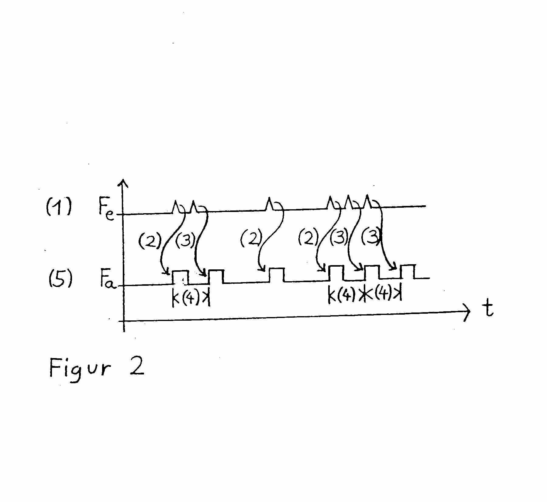
Figure taken from DE3842874
This place covers:
Special logic at register outputs e.g. for a counter value dependent reset.
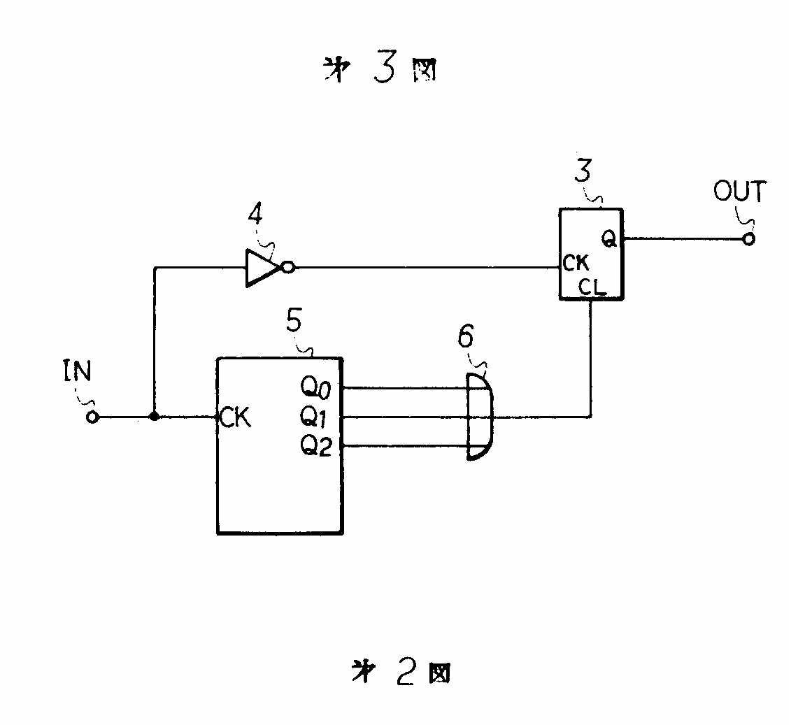
Figure taken from JP57199337
This place covers:
Logic counter having multiple counting stages including a carry over bit between stages.
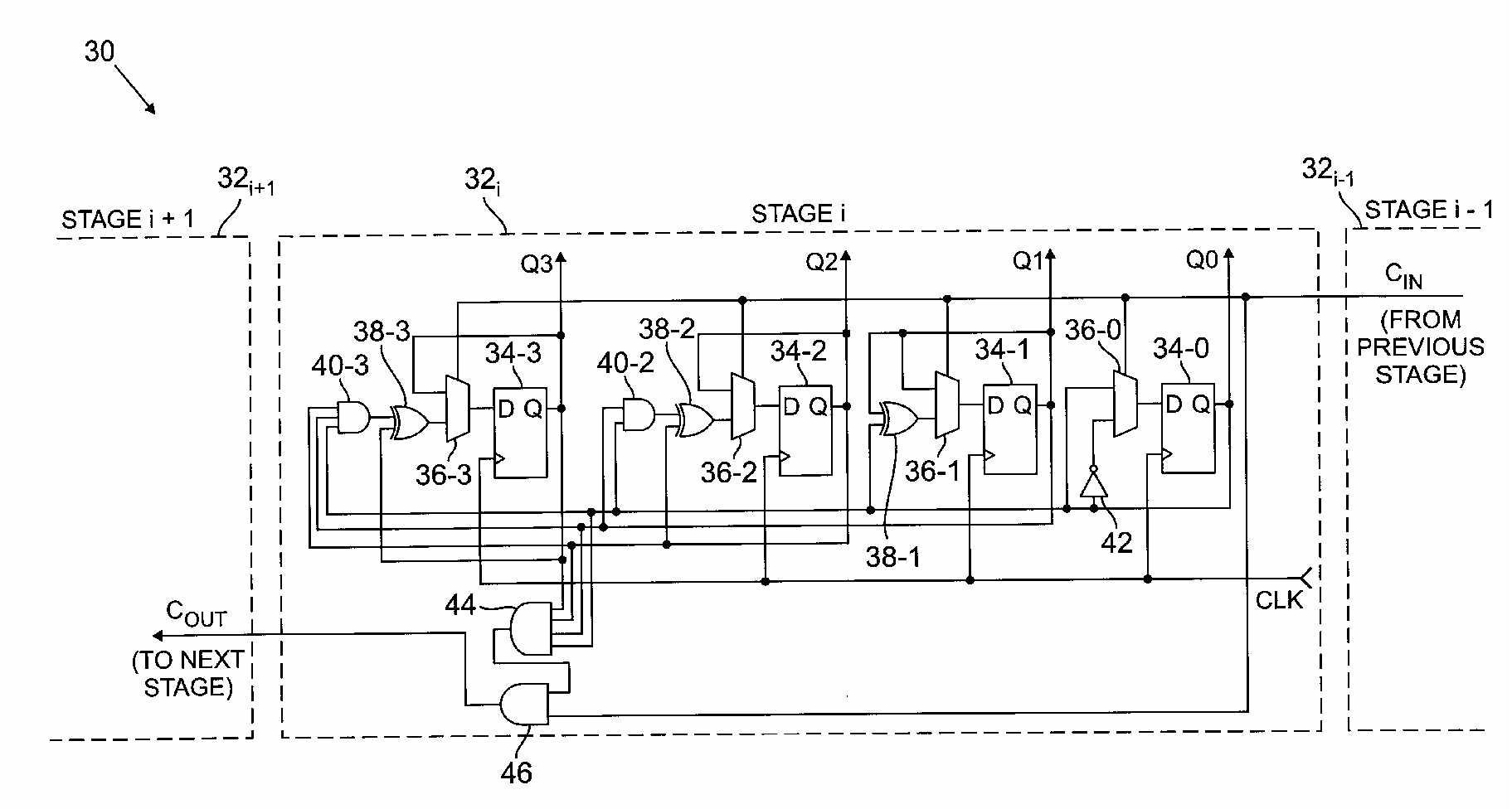
Figure taken from US5,946,369
This place covers:
Logic for representing the result to a user.

Figure taken from DE3031612
This place covers:
Logic for influencing the counter status.
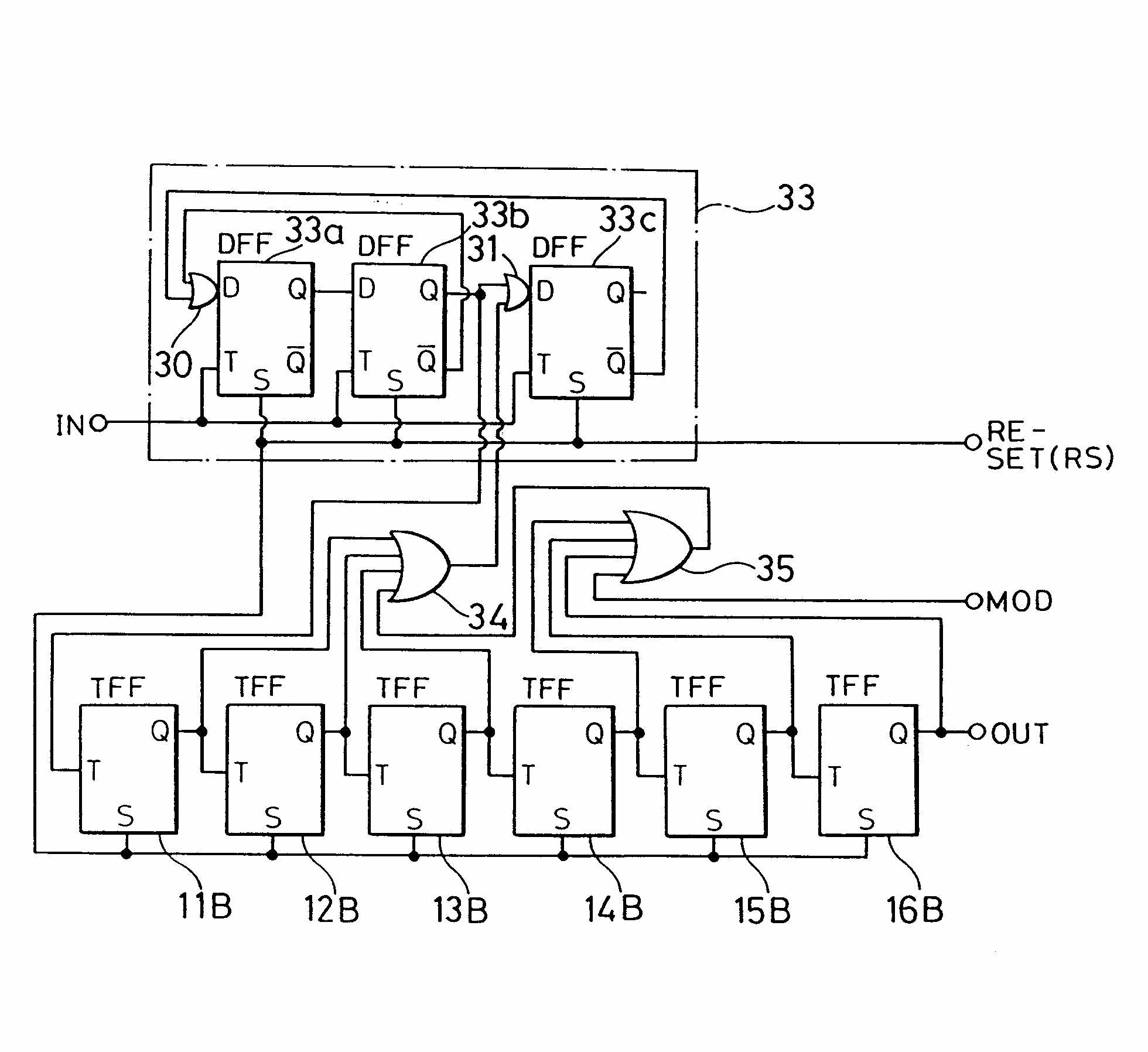
Figure taken from EP0471390.
This place covers:
Monitoring whether an error occured during the counting process (not the process producing the pulses)
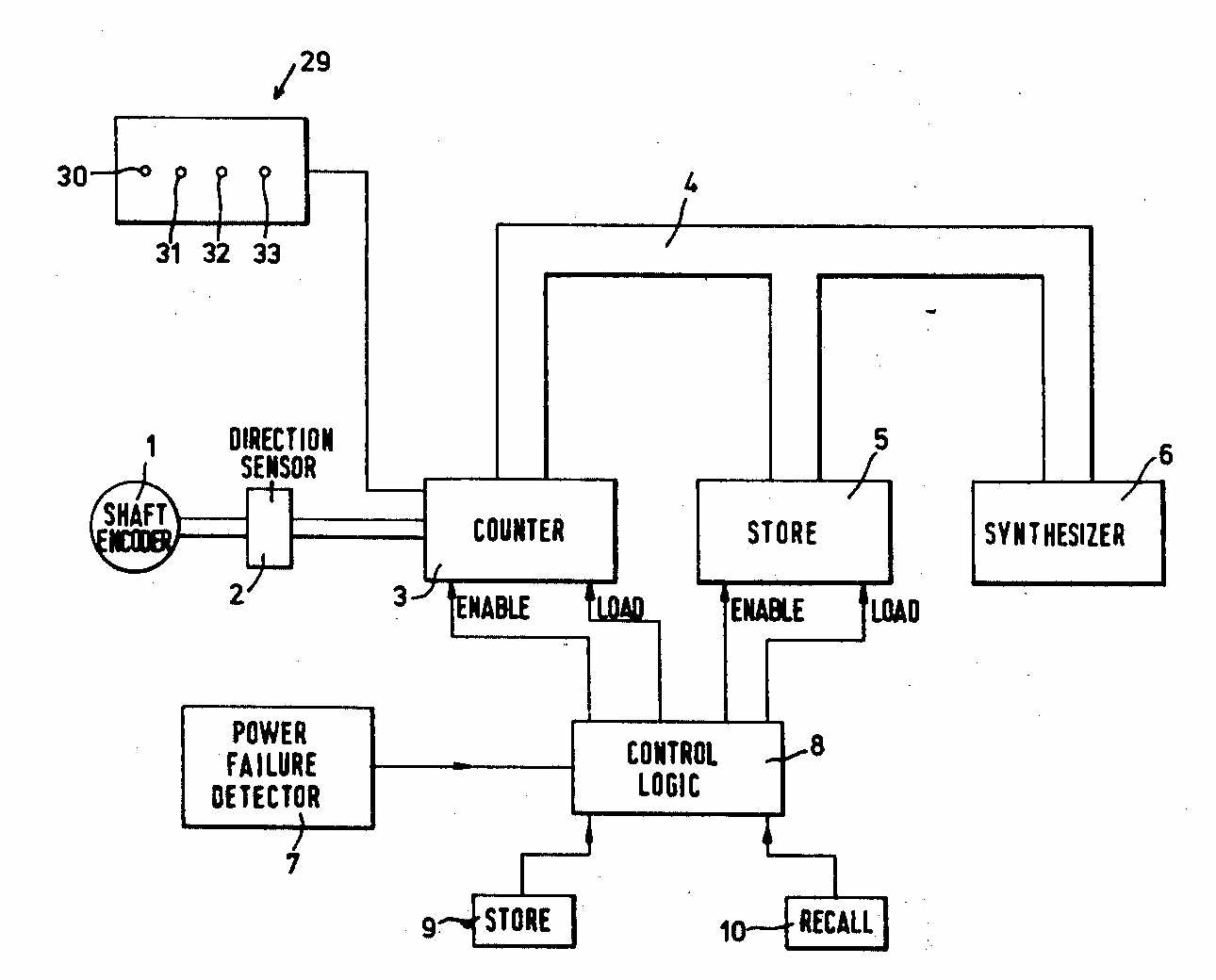
Figure taken from DE2550177
This place covers:
Logic for digital counting chains used in pulse counters or frequency dividers
This place covers:
Other elements as complementary IGFET's, electrically-ignited compounds e.g. pyrotechnical static relays
This place covers:
Detailed counting encoding scheme.
This place covers:
Details regarding the clock used for triggering the counting of incoming pulses
This place covers:
Counter with a "rippling" trigger pulse form stage to stage - asynchronous counters.
This place covers:
Variable counting base, non-integer or odd-number counters.
Attention is drawn to the following places, which may be of interest for search:
Unijunction transistors |
This place covers:
Static storage type counters - e.g. capacitive type
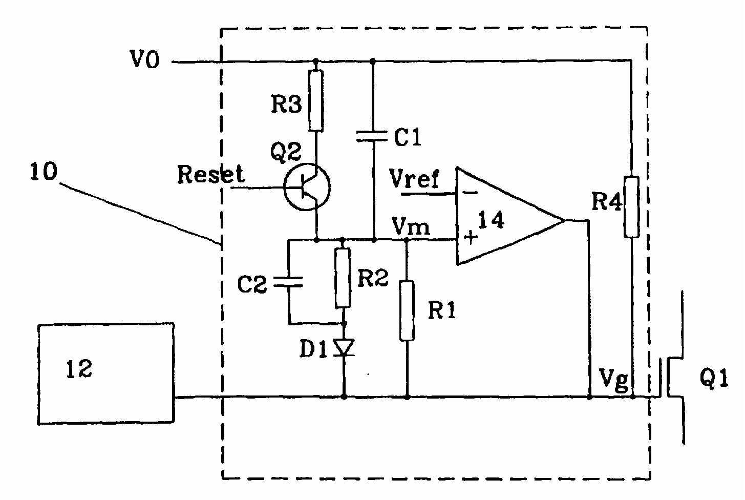
Figure taken from EP0916188
This place covers:
Figure taken from GB2008296.
This place covers:
A triggering pulse is generated in response to each input signal to be counted. The triggering pulse is applied to the device to change the voltage across the device. The voltage across the device is output as an indication of the number of received input signals. The device may be a resonant tunnelling diode with multiple peaks in its current versus voltage characteristic. The device may be a resonant tunnelling diode with multiple peaks in its current versus voltage characteristic.
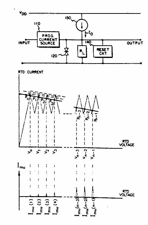
Figure taken from US 5,033,069
Attention is drawn to the following places, which may be of interest for search:
Capacitive touch switches |