CPC Definition - Subclass B23C
This place covers:
Milling machines, milling tools, milling methods and milling devices able to be attached to a machine tool other than a milling machine for milling metal and metal-like workpieces.
Milling should be interpreted as the removal of material in the form of chips from a workpiece by a rotating tool with a geometrically defined cutting edge wherein the main cutting force is generated as a result of the rotation of the tool in order to produce a shaped surface on the workpiece.
Cutting inserts, which are suitable for both milling and turning or for which no particular application is given are classified in B23B 27/14.
Milling of threads and tools for milling threads are classified in B23G.
Milling of gears is classified in B23F. Some gear milling tools may be classified in B23C as well if the disclosure is relevant for the general field of milling.
There is overlap with the circular sawing field (B23D 61/02) as some tools can be used as either milling cutters or saws.
This place does not cover:
Milling threads, tools for milling threads | |
Making particular items using non-specified or well-known milling techniques | B23P 15/00 or classed with product |
Making milling tools other than by milling | |
Multi stage processes involving milling and also other operations classed in B23B, B23D, B23F and B23G, making particular items. | |
Details of machine tools and accessories not related to the operation being performed including: | |
Clamping systems for workpiece tables | |
- tool changing | |
- conveying workpiece into and from machine | |
- evacuation of swarf, | |
- guarding & protective coverings | |
Adaptive control and/or computer controls for milling processes | |
- measuring or sensing | |
Milling of wood | |
Milling of stone and glass | |
Cutting inserts characterised only by the composition of the hard metal material | |
Cutting inserts characterised only by the composition of the diamond cutting material | |
Cutting inserts characterised only by the composition of the coating |
Attention is drawn to the following places, which may be of interest for search:
Cleaning | |
Production by reshaping | |
Sintering | |
Turning/boring/drilling | |
Broaching/sawing/planing | |
Shearing of metals | |
Sawing | |
Production of gears | |
Making gears | |
Thread cutting | |
Making particular objects | |
Details of machine tools | |
Copying mechanisms | |
Grinding and production of lenses. | |
Cutting of non-metals by severing | |
Working of plastics | |
Ceramic products | |
Hard metal, composition of CBN compacts | |
Diamonds | |
Coatings | |
Keys | |
Numerical control | |
Optical recognition system | |
Motors |
The use of Indexing Codes within the series B23C is widespread in the subclass. Indexing Codes should be allocated at every opportunity. When classifying milling cutters and milling inserts particular attention should be paid to the Indexing Codes. Indexing Codes should also be added routinely to give details of the workpiece or tool configuration, when this is not implicit in the classification system. For example a document showing a particular tool using machining of a crankshaft may be given a class for inventive information only for the details of the milling cutter. Such a document should also be allocated Indexing Codes relating to the workpiece type, the method of milling and/or further details of the milling cutter itself to allow easy retrieval.
The number of 200 series Indexing Codes is too high to list individually. Where the allocation of Indexing Code is compulsory, this is indicated in the templates for the main-group at the sub-group level.
- An set of drawings is provided under the definition statement for each main group. These drawings illustrate by example the content of the most widely used groups in this sub-class. Each of the drawings is taken from a document within from the group.
This place covers:
machines designed primarily for milling metallic materials.
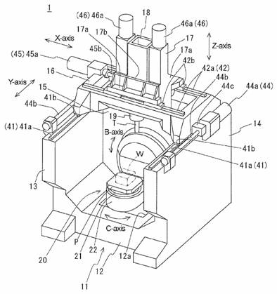
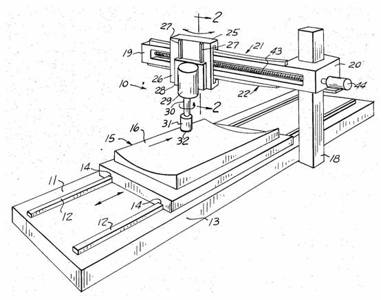
Gantry milling device (note also B23Q 1/012 portal machines)
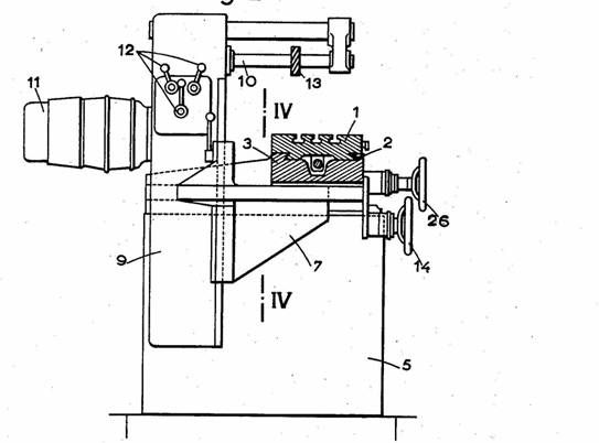
Milling machine with adjustable working spindle
vertical milling machine
This group does not cover multi-purpose machines (e.g. jig borers, horizontal borers etc) that can perform drilling, milling and other operations. These types of machine are classified in B23Q with details of their constructional details.
Classification is generally per literal interpretation of the group and sub-group headings.
Further details of subgroups
Subgroups B23C 1/16 and B23C 1/18 are not used. Refer to B23Q 35/00
This place covers:
Milling particular work.
Rail milling device
Milling spherical surfaces
Engine valve seat milling tool
Seat milling tool for valve seat in a valve
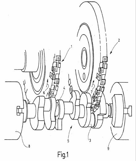
Milling crankshafts
Finishing or trimming edges includes deburring by milling
Milling edges off inside of pipe
Portable device for chamfering edges
B23C 3/18 (and B23C 2215/44)
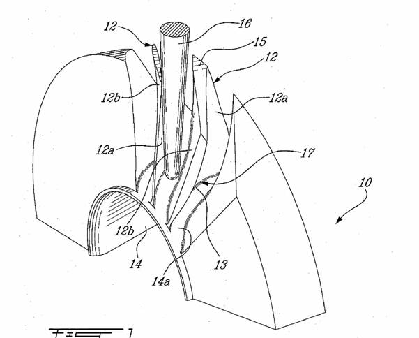
Milling turbine blades
Milling dies
B23C 3/28 (and B23C 2220/366)
Milling grooves for turbine blades
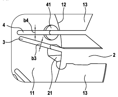
Milling straight grooves in CV joint hub (7)
Milling helical grooves in cable drum.
Note B23G 1/32 threading by milling.
Milling of keys
This place does not cover:
The production of items by the use of milling techniques which are known per se. |
Classification is generally per literal interpretation of the group and subgroup headings. The following should be noted:
Further details of subgroups
- B23C 3/00: Miscellaneous milling operations for operations not provided in subgroups but where the milling process per se is relevant.
- B23C 3/02: Milling surfaces of revolution including orbital drilling. For orbital drilling, also allocate the Indexing Code B23C 2220/52.
- B23C 3/05: Milling valve seats, includes boring units.
- B23C 3/06, B23C 3/08: Milling crankshafts or camshafts. See also B23B 5/18 (turning) and B23D 37/005 (broaching).
- B23C 3/10: Milling of relief surfaces, including the milling of relief surfaces on tools
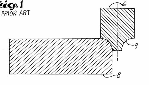
- B23C 3/12: Trimming edges (deburring by milling). Note deburring by grinding is classified in B24, deburring by scraping in B23D 79/00, deburring by chamfering drilled hole in B23B 51/10.
- B23C 3/16 Within this subgroup the terms "scrubbing" and "peeling" are synonyms for "milling". The important qualifier in this subgroup is the ingot (or similar workpiece).
- B23C 3/18: Milling curved surfaces of turbine blades etc. Note production of turbine blades B23P 15/02 and B23P 15/04.
- B23C 3/28: Milling grooves, including retaining grooves in turbine blades etc.
- B23C 3/35: Milling keys. Keys in this groups are the devices that fit in locks, not devices to prevent rotation between two objects. Optical recognition systems G06K. Keys per se E05B 19/00. Note the particular Indexing Codes B23C 2235/00 - B23C 2235/48.
B23C 3/355 should be interpreted as holders for both the master key and the key forming the workpiece being cut.
B23C 3/36 milling of milling cutters. Note that making of milling cutters by multi-stage processes (whether or not including milling) is classed in B23P 15/34. B23C 3/36 relates to the details of the process of milling milling cutters wherein the milling in itself is of interest.
Classification is generally per literal interpretation of the group and subgroup headings.
Allocation of Indexing Codes from the section "Details of milling cutters" B23C 2210/00 is mandatory in B23C 5/00.
This place covers:
Plain cutters having a generally long (in relation to diameter) circumferential cutting surface. Generally no cutting on end surfaces.
Plain milling cutter:
This place does not cover:
Shank-type cutters, i.e. with an integral shaft |
This place covers:
Face-milling cutters used for producing flat surfaces that are at right angles to the axis of rotation of the cutter. Generally, the cutters cut a limited depth on the circumferential surface of the tool.
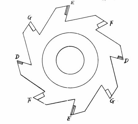
This place covers:
Cutters having a cutter body with the general configuration of a disc, i.e. a thin, flat, round shape, for cutting grooves or slots into the workpiece. Also known as side cutter or side-and-face cutter.
When the cutter divides or cuts a metal workpiece into two pieces, the cutter is considered a sawing tool and should be classified in B23D 45/00.
Milling cutters used in whirling processes should receive a classification in B23C 2220/68.
Plate-like cutting inserts fitted on a ring or ring segment attached to a separate, main tool body should be classified in the following: B23C 5/2234, B23C 5/226, B23C 5/2291 or B23C 5/2309.
This place covers:
An end mill (also called a slot drill) having a generally cylindrical shank with a cutting portion extending from the shank. The cutting portion is capable of cutting in the axial and radial directions by cutting edges on the circumferential and end surfaces of the cutting portion.
Milling cutter (slot drill) with shank having end cutters extending to cutter axis to enable axial feed:
Milling cutter with head detachable from shaft:
Milling cutter with shaft for roughing:
Note that milling cutters with shafts that include inventive features related to the securing or placement in the chuck are classified in B23B 31/005 or B23B 31/006, accompanied by Indexing Codes from B23B 2231/02 and subgroups.
Note that milling cutters with detachable heads are placed here with the allocation of Indexing codes B23C 2210/02 and/or B23C 2210/03 as appropriate. A detachable head is generally seen as being something attached to the end of the shank that covers the whole of the cross section of the shank.
This place covers:
Ball nosed milling cutter with removable insert.
This place covers:
A slot cutter that produces a finished slot in the shape of the letter "T" (also includes inverted letter "T").
This place covers:
Milling cutter with shaft and permanently attached inserts, e.g. via welding or brazing:
This place does not cover:
Ball nose end mills with permanently fixed cutting inserts | |
T slot cutters with permanently fixed cutting inserts |
Note that milling cutters with permanently attached inserts made of PCD or CBN are placed here with the allocation of Indexing codes B23C 2226/315 for PCD or B23C 2226/125 for CBN.
This place covers:
Milling cutter with shaft and removable inserts.
Note that milling cutters with detachable heads are not classed in B23C 5/109 but in B23C 5/10 with the allocation of Indexing Codes B23C 2210/02 and/or B23C 2210/03 as appropriate. A detachable head is generally seen as being something attached to the end of the shank that covers the whole of the cross section of the shank.
This place covers:
Cutters for producing a particular profile, i.e. cutting edge shape has a direct correlation to the finished shape of the workpiece.
This place does not cover:
Shank-type cutters, i.e. with an integral shaft |
Indexing Codes for chamfering (B23C 2220/16) and turbine blade grooves (B23C 2220/366) should be considered if those profiles are present.
This place covers:
Milling cutter with permanently fixed inserts.
Attention is drawn to the following places, which may be of interest for search:
Shank-type cutters with permanently fixed cutting inserts |
This place covers:
Removable cutting inserts that are generic, i.e. no special shape or special features.
Documents classified in B23C 5/20, B23C 5/22 and B23C 5/24 should also receive Indexing Codes from group B23C 2200/00 entitled "Details of milling inserts" when applicable. Indexing Codes should be allocated only for special features of the insert.
For example, if the insert has a fixation hole of a special shape, the appropriate Indexing Code (B23C 2200/361) should be given. This Indexing Code should not, however, be given to every insert having a fixation hole.
An Indexing Code from the group B23C 2200/00 entitled "Details of cutting inserts" takes precedence over an Indexing Code from other groups.
For example, an insert with a curved cutting edge should be allocated the Indexing Code B23C 2200/203. The allocation of B23C 2210/084 is not necessary or desired.
This place covers:
Removable cutting inserts having a special shape. The shape may be considered special by virtue of, inter alia, the overall shape and cutting edge configuration.
Examples:
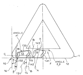
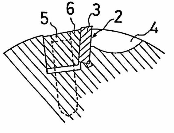
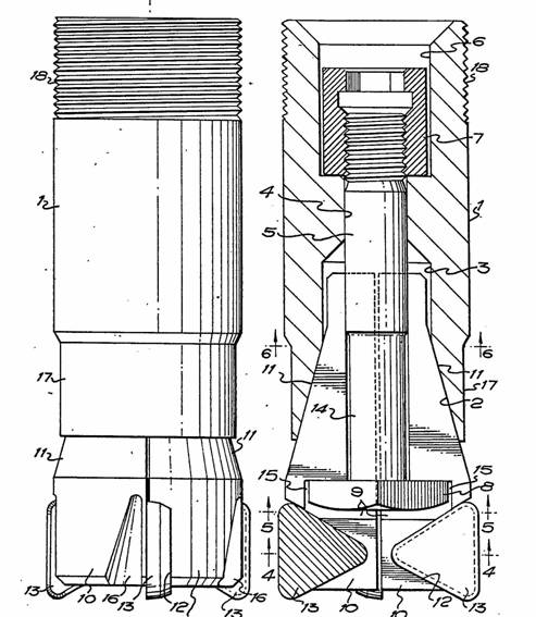
Tangentially mounted milling insert:
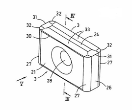
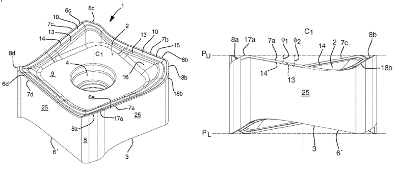
Milling insert with curved cutting edge and wiper:
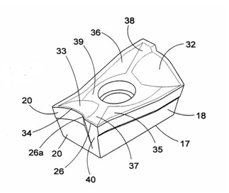
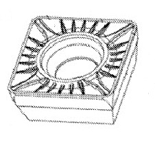
Milling insert with interrupted cutting edge and chip-breaking projections on the top surface:
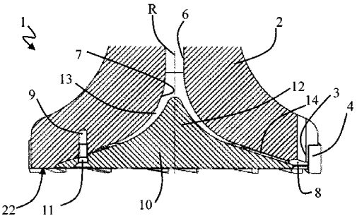
Milling insert with sloped cutting edges (6a-d) and rake faces (10) above a central surface (9):
B23B 27/141, B23B 27/143 and B23B 27/145 are the equivalent subgroups for turning or general-purpose inserts. If the insert can be used for turning and milling only a class in B23B 27/141, B23B 27/143 or B23B 27/145 is given.
This place does not cover:
Cutting insert having special form related to the securing arrangement within the holder |
Note that end mills with detachable heads are not classified as end mills with cutting inserts in B23C 5/202, but in B23C 5/10 with the Indexing Codes B23C 2210/02 or B23C 2210/03 as appropriate.
Inserts having a special shape by virtue only of the chip-breakers are classed in B23C 5/205.
Cutting inserts having a special shape related to securing the cutting inserts, e.g. locating or clamping the insert within the holder, should be classified in B23C 5/22 or subgroups B23C 5/2204, B23C 5/2208, B23C 5/2239, B23C 5/2243, B23C 5/2265, B23C 5/2269, B23C 5/2295, B23C 5/2298 or B23C 5/2301 according to the clamping mechanism.
Cutting inserts having a special shape that is not related to securing or locating the cutting insert within the tool body and a special shape that is related to securing or locating the cutting insert within the tool body should be classified in B23C 5/202 (or subgroup B23C 5/205) and B23C 5/22 (or subgroups).
This place covers:
Inserts having a special shape by virtue only of the chip-breakers.
Examples:
This place covers:
Special arrangements of how the cutting inserts are fastened to the cutter body.
Cutting inserts having a special shape that is not related to securing or locating the cutting insert within the tool body and a special shape that is related to securing or locating the cutting insert within the tool body should be classified in B23C 5/202 (or subgroup B23C 5/205) and one of the following subgroups according to the clamping mechanism: B23C 5/2213, B23C 5/2247, B23C 5/2273 or B23C 5/2304.
Documents classified in B23C 5/20, B23C 5/22 and B23C 5/24 should also receive Indexing Codes from group B23C 2200/00 entitled "Details of milling inserts" when applicable. Indexing Codes should be allocated only for special features of the insert. For example, if the insert has a fixation hole of a special shape, the appropriate Indexing Code (B23C 2200/361) should be given. This Indexing Code should not, however, be given to every insert having a fixation hole.
An Indexing Code from the group B23C 2200/00 entitled "Details of cutting inserts" takes precedence over an Indexing Code from other groups. For example, an insert with a curved cutting edge should be allocated the Indexing Code B23C 2200/203. The allocation of B23C 2210/084 is not necessary or desired.
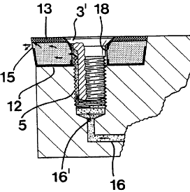
This place covers:
Plate-like cutting inserts clamped against walls of the recess in the shank by a clamping member acting upon the wall of a hole in the insert.
This place does not cover:
For plate-like cutting inserts fitted on an intermediate carrier, e.g. shank fixed in the cutter body | |
For plate-like cutting inserts fitted on a ring or ring segment |
This place covers:
Plate-like cutting inserts of special shape where clamping against the walls of a pocket by means of something acting on the hole in the insert is also important. The shape may be considered special by virtue of, inter alia, the overall shape and cutting edge configuration.
Example:
Insert has a special shape due to the fixation hole being widened at the bottom to permit the inclined orientation of the fastener and the fastener interacts with the sidewall of the hole in the insert.
This place covers:
Plate-like cutting insert clamped against walls of the recess in an intermediate carrier of the cutter body by a clamping member acting upon the wall of a hole in the insert.
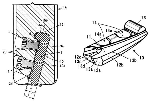
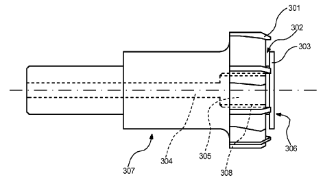
Example:
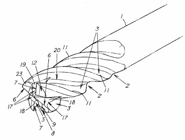
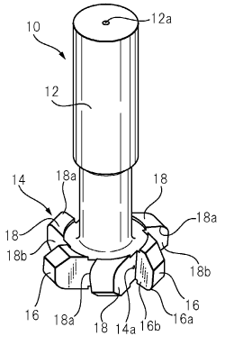
Intermediate carrier (10) with insert (11)
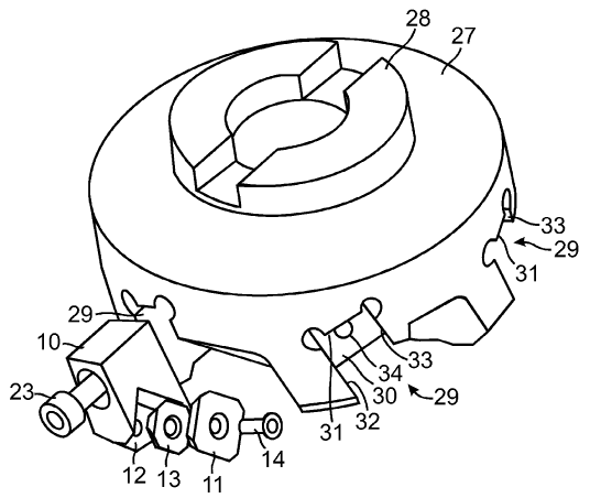
Example:
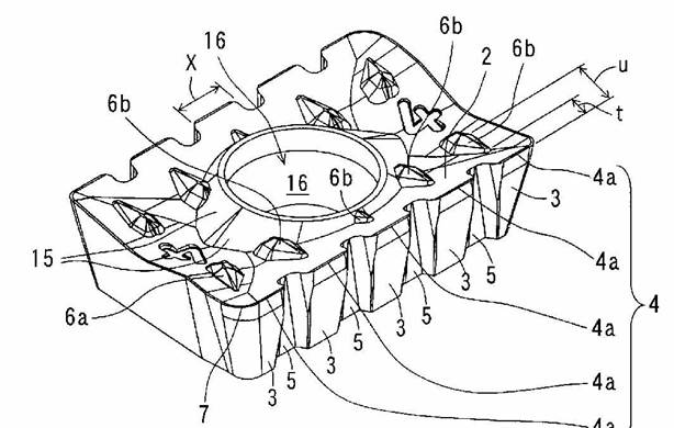
Intermediate carrier (A) formed as a shank for insert (B)
This place covers:
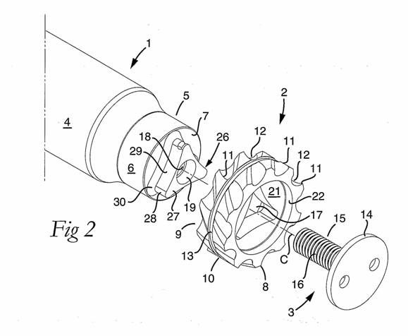
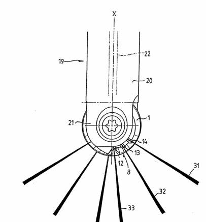
Plate-like cutting inserts clamped against walls of the recess in a shank (16) by a clamping member (14) acting upon the wall of a hole in the insert, and fitted on a ring (10):

This place covers:
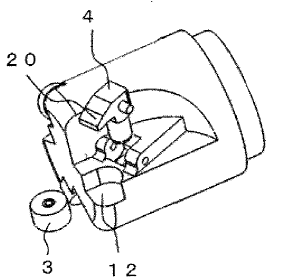
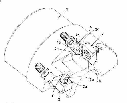
Plate-like cutting inserts clamped by clamping member (32) acting almost perpendicular on the cutting face:
This place covers:
Plate-like cutting inserts (3) clamped by a clamping member (4) acting almost perpendicular on the cutting face:
This place does not cover:
For plate-like cutting inserts fitted on an intermediate carrier, e.g. shank fixed in the cutter body | |
For plate-like cutting inserts fitted on a ring or ring segment |
This place covers:
Plate-like cutting inserts of special shape clamped by member acting on top surface. The shape may be considered special by virtue of, inter alia, the overall shape and cutting edge configuration.
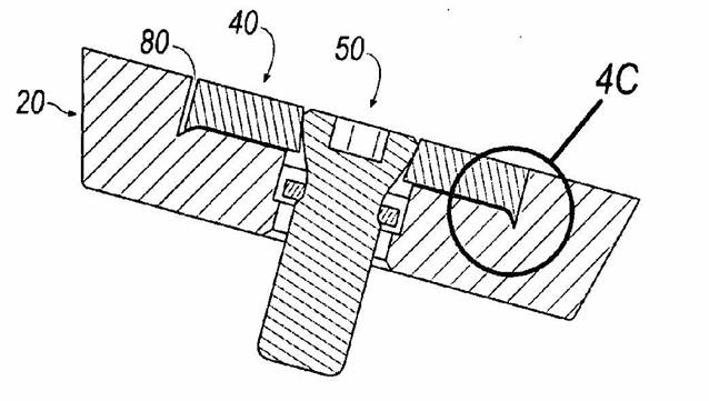
Plate-like cutting insert (10) having a special shape and clamped by clamping member (20) acting almost perpendicular (14) on the cutting face:
This place covers:
Plate-like cutting inserts (30) clamped by a clamping member (40) acting almost perpendicular on the cutting face, and fitted on an intermediate carrier (20):
This place covers:
Generic, i.e. no special shape or special features, plate-like milling inserts clamped by a wedge.
This place does not cover:
For plate-like cutting inserts fitted on an intermediate carrier, e.g. shank fixed in the cutter body | |
For plate-like cutting inserts fitted on a ring or ring segment |
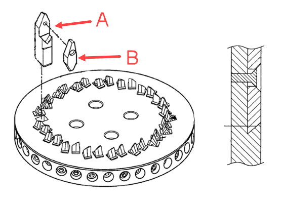
This place covers:
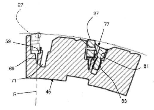
Example:
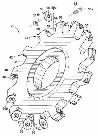
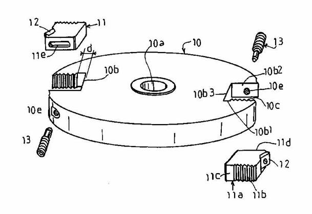
Plate-like cutting insert (27) fitted on a ring segment (45) and secured by a wedge (77).
This place covers:
Simultaneous clamping of all cutting inserts.
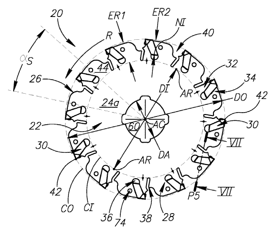
This place covers:
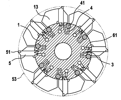
Example:
Plate-like cutting insert (5, 51) fitted on a ring segment (13) and secured by resilient/flexible means (3, 4).
This place covers:
Features relative to the adjustment of the insert relative to the cutter body.
Documents classified in B23C 5/20, B23C 5/22 and B23C 5/24 should also receive Indexing Codes from group B23C 2200/00 entitled "Details of milling inserts" when applicable. Indexing Codes should be allocated only for special features of the insert.
For example, if the insert has a fixation hole of a special shape, the appropriate Indexing Code (B23C 2200/361) should be given. This Indexing Code should not, however, be given to every insert having a fixation hole.
An Indexing Code from the group B23C 2200/00 entitled "Details of cutting inserts" takes precedence over an Indexing Code from other groups.
For example, an insert with a curved cutting edge should be allocated the Indexing Code B23C 2200/203. The allocation of B23C 2210/084 is not necessary or desired.
This place covers:
Adjustment of insert position by oblique surfaces.
This place covers:
Adjustment of position of insert by notches.
This place covers:
Adjustment of insert position by means of serrations
This place covers:
Adjustment of insert position by means of screws.
This place covers:
Adjustment of insert position by means of spacers.

This place covers:
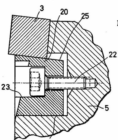
Adjustment of insert position by means of rotating an eccentric, i.e. an object that is not perfectly circular.
This place covers:
Adjustment of insert position by means of hydraulics.
This place covers:
Adjustment by means of elastically deforming the tool carrier.
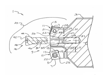
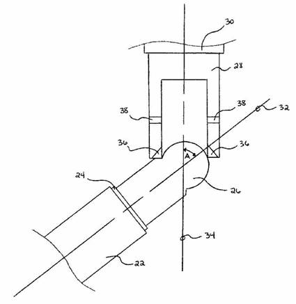
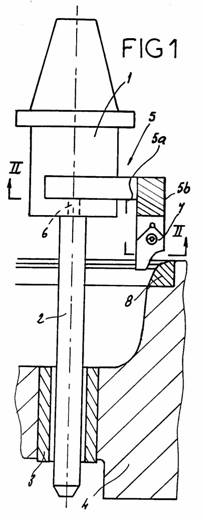
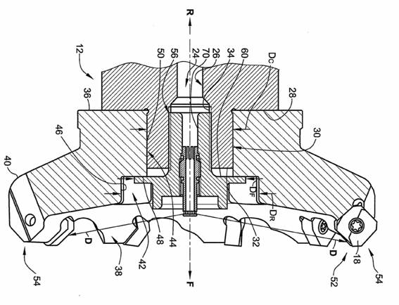
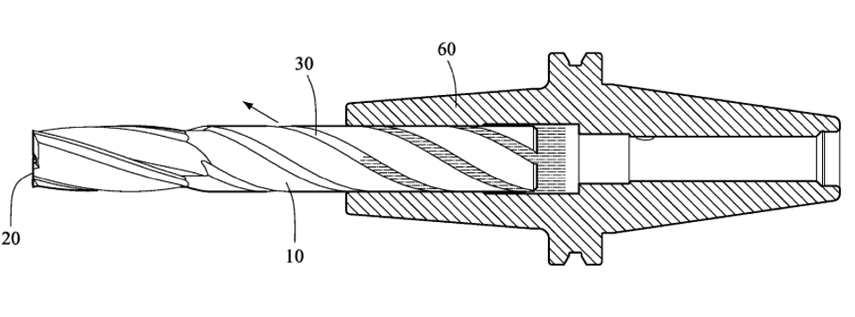
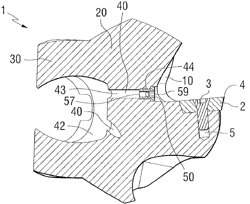
This place covers:
Details of arrangements for securing cutters to the spindle, including details of intermediate connecting members, e.g. arbors.
Attention is drawn to the following places, which may be of interest for search:
Chucks |
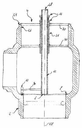
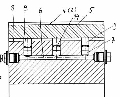
This place covers:
Features concerning cooling arrangements within or on the cutter body. This area does not include cooling features of the machine in general.
See also B23B 27/10, B23B 51/06 and B23D 77/006 for equivalents in turning, drilling & reaming respectively.
Attention is drawn to the following places, which may be of interest for search:
Arrangements for cooling or lubricating tools or work, in general |
Note also the Indexing Code relating to cooling (B23C 2250/12) for non-invention information.
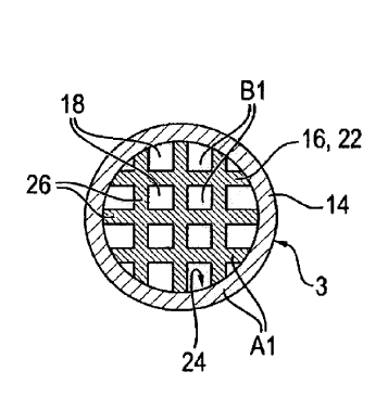
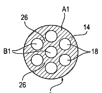
This place covers:
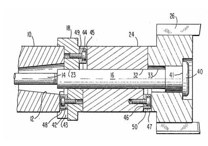
Milling cutters with means for coolant to move along the outside of the tool periphery toward cutting edges. This area is not meant for coolant outlets that exit from an interior channel into the chip flutes that then guide the coolant toward the cutting edges.
This place covers:
Special details of the coolant channel(s) cross-sectional shape (cross-section not required to be perpendicular to rotation axis of cutter body). The term "special" means non-generic details of the cross-sectional shape, e.g. mere cross-sections of a single circular nature would be excluded from this sub-class.
This place covers:
Cutting inserts with interior coolant channels.
Example:
Example:

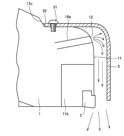
This place covers:
Nozzles to point or direct the coolant in a desired direction.
This place covers:
Deflector to point or direct the coolant in a desired direction.
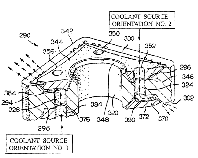
This place covers:
Deflector intersects the rotational axis of the cutter body such that coolant is deflected at the rotational axis.
Example:
Example:
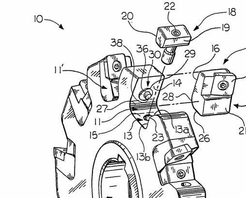
This place covers:
Milling devices able to be attached to a machine tool
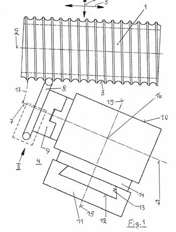
Device attached to a lathe to allow milling
Classification is per literal interpretation of the group and subgroup headings. The term "machine tool" should be interpreted as a machine tool not normally capable of performing milling. Devices for attachment into the spindle (speed changers, angled heads, offset heads) are classified in B23Q 5/04. The term "device" should be interpreted as a discrete device, so lathes with provision for performing milling as a result of integrated features will not be classed here.
This place covers:
Details or accessories so far as specially adapted to milling machines or cutters
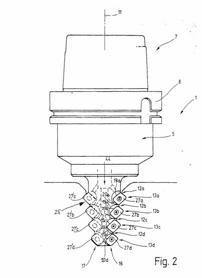
Milling head.
Classification is generally per literal interpretation of the group and subgroup headings.
The term "specially adapted to milling machines" should be interpreted narrowly as adapted to machines specifically designed for performing milling operations. Details of machines performing milling and other operations should be classified in B23Q. This group includes milling templates. Obviously with the move towards multi-function machine tools, this group has become less well-used.
Details or accessories of machine tools in general & copying devices are classified in B23Q.
B23C 9/005 Milling heads may mean details of the heads of milling machines including the main spindle of a machine tool or a head able to be attached to a machine tool for the specific purpose of milling. Machining heads used on gantry machines with multiple axes or movement are classified in the relevant subgroup of B23Q 1/25. Machining heads characterised by the mechanisms for driving the spindle or for providing feeding motion ar classified in B23Q 5/00. Detachable heads including speed changers, offset drives or right angled drives for general work are classed in B23Q 5/04.
Attention is drawn to the following places, which may be of interest for search:
Milling cutting inserts by chip breaking depressions |
Attention is drawn to the following places, which may be of interest for search:
Lines for indexing round inserts |
Attention is drawn to the following places, which may be of interest for search:
Projections on rake or top surfaces |
Attention is drawn to the following places, which may be of interest for search:
Details of connections of tools or workpieces |
Attention is drawn to the following places, which may be of interest for search:
Details of milling cutters being angles | |
Side or top views of the cutting edge | |
Cross section of the cutting edge |
Attention is drawn to the following places, which may be of interest for search:
Roughing and finishing |
Attention is drawn to the following places, which may be of interest for search:
Materials of tools or workpieces composed of steel |
Attention is drawn to the following places, which may be of interest for search:
Materials of tools or workpieces composed of high-speed steel |
Attention is drawn to the following places, which may be of interest for search:
Working stone or stone-like materials by milling, e.g. channelling by means of milling tools |
Attention is drawn to the following places, which may be of interest for search:
Working stone or stone-like materials by milling, e.g. channelling by means of milling tools |
Attention is drawn to the following places, which may be of interest for search:
Chip breaking or chip evacuation |
Attention is drawn to the following places, which may be of interest for search:
Fixation of inserts or cutting bits in the tool |
Attention is drawn to the following places, which may be of interest for search:
Damping vibrations during milling |
Attention is drawn to the following places, which may be of interest for search:
Balancing the cutter during milling |
Attention is drawn to the following places, which may be of interest for search:
Auxiliary treatment of workpieces, immediately preceding a cutting tool |
Attention is drawn to the following places, which may be of interest for search:
Compensating adverse effects of centrifugal force during milling |