CPC Definition - Subclass H03D
This place covers:
Demodulation or transference of signals modulated on a sinusoidal carrier or on electromagnetic waves.
The modulation and demodulation of pulse trains, for example in Pulse Width Modulation circuits, is covered in subclass H03K.
System aspects of modulation by digital signals of the frequency, phase or amplitude of a sinusoidal carrier, or carriers, for example in quadrature (I-Q) modulation systems, and the demodulation thereof, is covered in subclass H04L.
Analogue quadrature modulation used in the NTSC and PAL colour television systems (where the I and Q signals representing colour difference values are substantially continuously variable), and the demodulation of these signals, is covered in H04N.
The modulation of sinusoidal signals, for example in AM and FM broadcasting, is covered in sub class H03C.
This place does not cover:
Masers, lasers | |
Circuits capable of acting both as modulator and demodulator;balanced modulators | |
Details applicable to both modulators and frequency changers | |
Demodulating pulses which have been modulated with a continuously variable signal | |
Transforming types of pulse modulation | |
Phase locked loops; phase comparators therein | |
Relay systems, e.g. repeater stations | |
Demodulators adapted for digitally modulated-carrier systems | |
Synchronous demodulators adapted for colour television |
Attention is drawn to the following places, which may be of interest for search:
In this place, the following terms or expressions are used with the meaning indicated:
Homodyne, synchrodyne or zero-IF receiver | A receiver in which the local oscillator (LO) frequency is set to the same frequency as the received RF carrier frequency resulting in direct conversion of the received signal to a baseband (or zero IF) frequency for information recovery. In a near-zero IF receiver, the LO frequency is set very close to the carrier frequency of the RF signal. |
Superheterodyne receiver | A receiver in which a received RF signal is converted to an intermediate frequency (IF) by at least one stage of frequency conversion (e.g. a 'mixer' stage which forms the product of the RF signal and a local oscillator signal) |
In patent documents, the following abbreviations are often used:
Superhet | A superheterodyne receiver |
Double (multiple) superhet | A double-conversion receiver using two intermediate frequencies, i.e. a superhet receiver in which a received RF signal passes through two (or more) successive stages of frequency conversion to different intermediate frequencies, one of which may be zero-IF or baseband. |
This place covers:
Demodulation of signals being amplitude-modulated on a sinusoidal carrier.
This place does not cover:
Circuits for demodulating amplitude-modulated or angle-modulated oscillations at will | |
Demodulation or transference of modulation of modulated electromagnetic waves | |
Super-regenerative demodulator circuits | |
Amplitude demodulators adapted for digitally modulated-carrier systems, e.g. using on-off keying; Single sideband orvestigial sideband modulation |
Attention is drawn to the following places, which may be of interest for search:
Homodyne or synchrodyne single sideband receivers |
In this place, the following terms or expressions are used with the meaning indicated:
IP2 | Second Order Intercept Point |
IM2 | Second order intermodulation product |
This place covers:
Example:
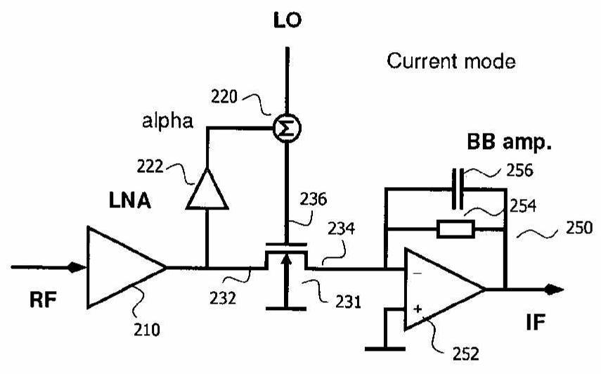
WO2011047703
IM2 reduction e.g. by summing RF signal to LO
This place covers:
Example:
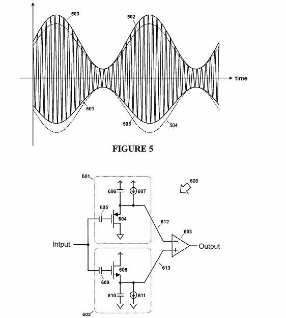
US2009015295
Amplitude demodulation using e.g. MOS transistors
This place covers:
Example:
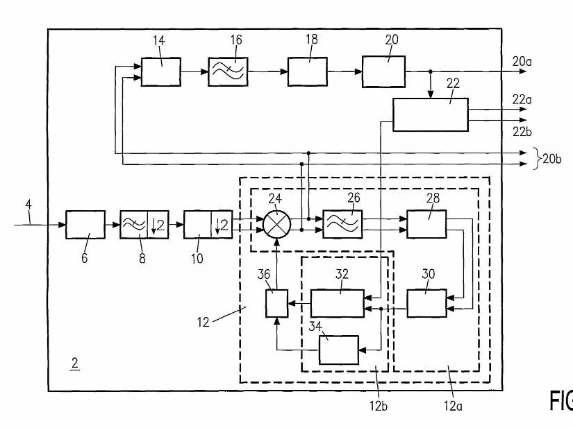
EP2315350
Demodulation using two quadrature channels (20b) and a PLL (12) in a synchronous circuit. (Analog/digital converter 6, decimation filter 8, Hilbert filter 10; elements 14, 16, 18, 20, 22 are not relevant for the demodulation principle)
Attention is drawn to the following places, which may be of interest for search:
Homodyne or synchrodyne receiver circuits |
Attention is drawn to the following places, which may be of interest for search:
Diodes used as switches |
This place does not cover:
Decoders for simultaneous demodulation and decoding of signals composed of a sum-signal and a suppressed carrier, amplitude modulated by a difference signal |
Attention is drawn to the following places, which may be of interest for search:
Mean frequency regulation of modulators using a phase locked loop |
This place does not cover:
Decoders for simultaneous demodulation and decoding of signals composed of a sum-signal and a suppressed carrier, amplitude modulated by a difference signal | |
Using two quadrature channels | |
Using a phase locked loop |
Attention is drawn to the following places, which may be of interest for search:
Receiver circuits |
This place covers:
Demodulation of angle-, frequency- or phase- modulated oscillations.
Example:
EP1163719
FM demodulation by conversion into two quadrature related signals
This place does not cover:
Circuits for demodulating amplitude-modulated or angle-modulated oscillations at will | |
Demodulation or transference of modulation of modulated electromagnetic waves | |
Super-regenerative demodulator circuits | |
Frequency demodulators adapted for digitally modulated-carrier systems, i.e. using frequency-shift keying | |
Phase demodulators adapted for digitally modulated-carrier systems, i.e. using phase-shift keying |
Attention is drawn to the following places, which may be of interest for search:
Arrangements for measuring frequencies; Arrangements for analyzing frequency spectra | |
Automatic bandwidth control | |
Muting in frequency-modulation receivers | |
Arrangements for limiting amplitude | |
Automatic frequency regulation in receivers | |
Automatic frequency control | |
Phase-locked loops in general | |
Multiple phase locked loops in general | |
Phase-locked loops using a controlled phase shifter in general | |
Phase-locked loops including two phase detectors in general |
In this place, the following terms or expressions are used with the meaning indicated:
I/Q | in-phase, quadrature |
This place does not cover:
Modifications of demodulators to reduce effects of temperature variations |
This place does not cover:
Angle demodulation by detecting phase difference between two signals obtained from input signal including locked-in oscillation circuits to reject or remove amplitude variations with means for eliminating interfering signals, e.g. by multiple phase locked loops |
Attention is drawn to the following places, which may be of interest for search:
Angle demodulation by detecting phase difference between two signals obtained from input signal including locked-in oscillation circuits to reject or remove amplitude variations combined with a phase locked loop demodulator | |
Changing frequency deviation for modulators |
This place does not cover:
Angle demodulation by converting the oscillations into two quadrature related signals |
This place does not cover:
Angle demodulation by detecting phase difference between two signals obtained from input signal including locked-in oscillation circuits to reject or remove amplitude variations using at least two phase detectors in the loop |
This place covers:
Example:
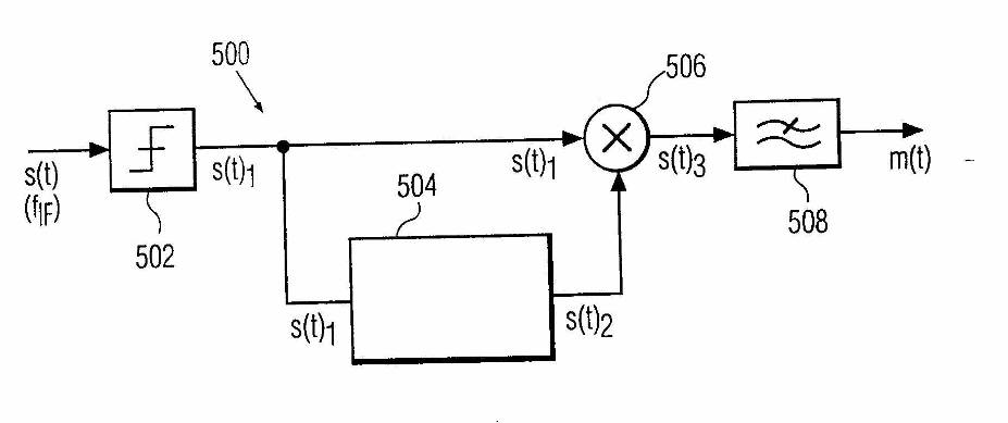
EP1040565
Phase demodulation by mixing of two signals obtained from input signal. A phase shifter network (504) provides a phase shift of 90° at the center frequency.
This place does not cover:
Attention is drawn to the following places, which may be of interest for search:
Muting in frequency-modulation receivers | |
Limiting arrangements |
Attention is drawn to the following places, which may be of interest for search:
Arrangements for measuring frequencies |
This place does not cover:
Angle demodulation by detecting phase difference between two signals obtained from input signal including locked-in oscillation circuits to reject or remove amplitude variations combined with means for obtaining automatic gain control |
Attention is drawn to the following places, which may be of interest for search:
PLLs using at least two phase detectors in the loop in general |
Attention is drawn to the following places, which may be of interest for search:
PLLs provided with an additional controlled phase shifter in general |
This place covers:
FM Demodulation by means of electromechanical devices such as FBARs or piezoelectric resonators.
This place does not cover:
Demodulation of angle-modulated oscillations by detecting phase difference between two signals obtained from input signal by combining signals additively or in product demodulators by means of electromechanical resonators |
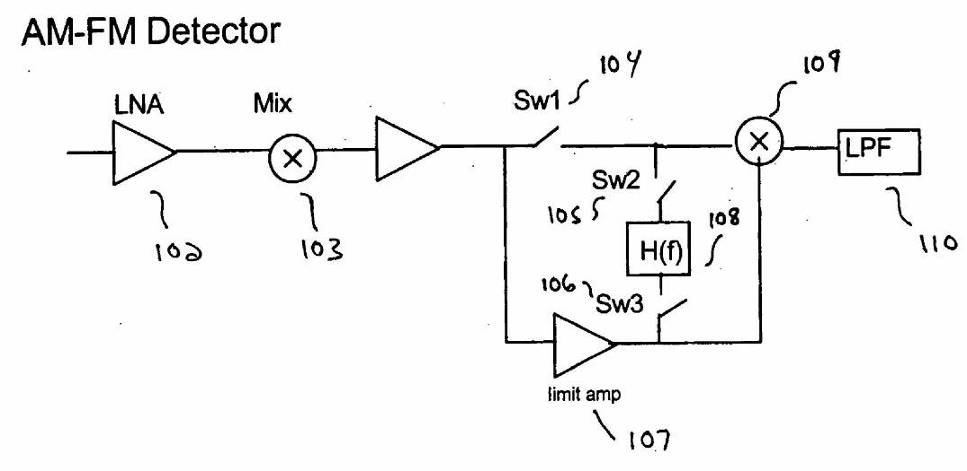
This place covers:
Circuits selectable between FM and AM demodulation
Polar or phase-amplitude demodulation
Example:
US2007178866
Demodulator switchable between AM demodulation
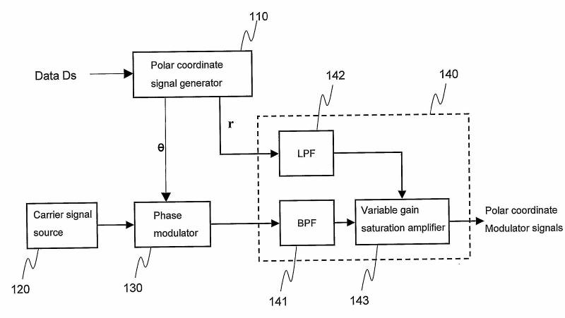
WO2007005139
Phase-amplitude-phase demodulation
This place does not cover:
Demodulation or transference of modulation of modulatedelectromagnetic waves | |
Super-regenerative demodulator circuits | |
Demodulators adapted for digitally modulated-carrier systems characterised by combinations of amplitude and angle modulation, e.g. quadrature-amplitude modulated carrier systems |
Attention is drawn to the following places, which may be of interest for search:
Polar or phase-amplitude modulation |
This place covers:
Mixer circuits in general, applicable to both transmitters or receivers.
This place does not cover:
Demodulation or transference of modulation of modulated electromagnetic waves | |
Super-regenerative demodulator circuits | |
Dielectric amplifiers, magnetic amplifiers, parametric amplifiers used as a frequency-changers H03F |
Attention is drawn to the following places, which may be of interest for search:
Arrangements for performing computing operations, multiplication or division |
This place covers:
Example:
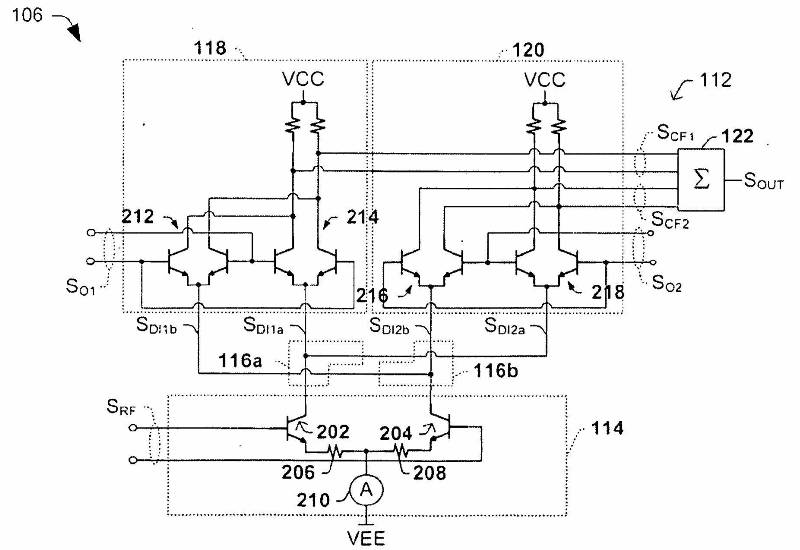
DE102010002575
Balanced active mixer arrangement (Gilbert type)
This place does not cover:
Balanced arrangements using a combination of bipolar transistors and field-effect transistors |
This place does not cover:
Balanced arrangements using a combination of bipolar transistors and field-effect transistors |
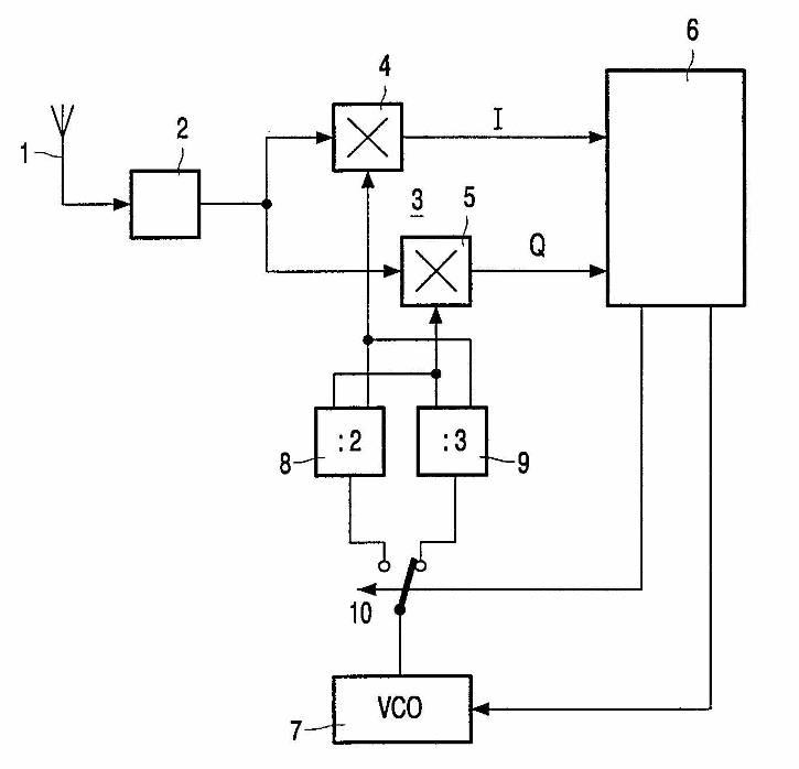
This place covers:
Examples:
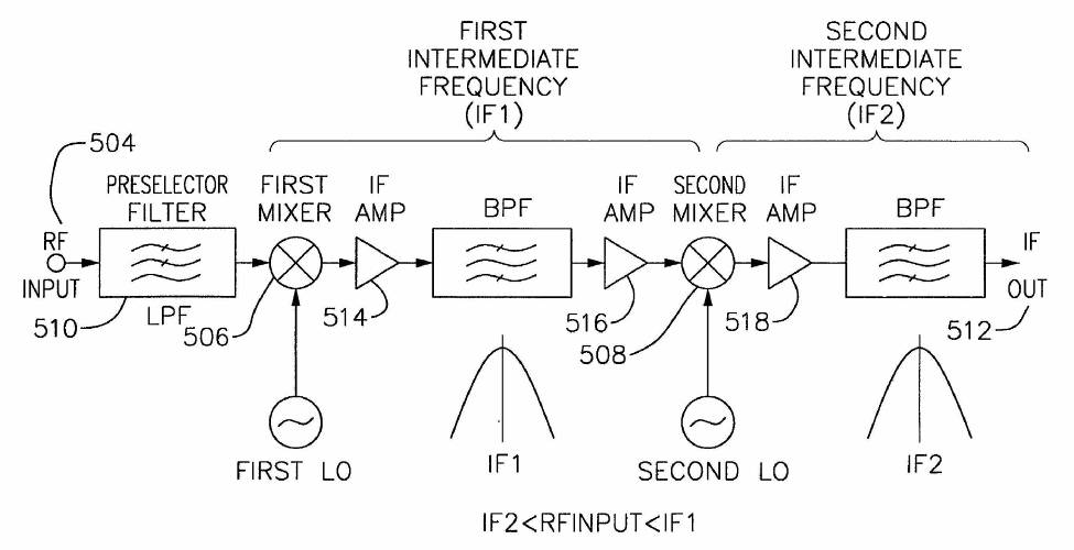
US2001007151
Dual conversion receiver using two frequency changers being connected in cascade
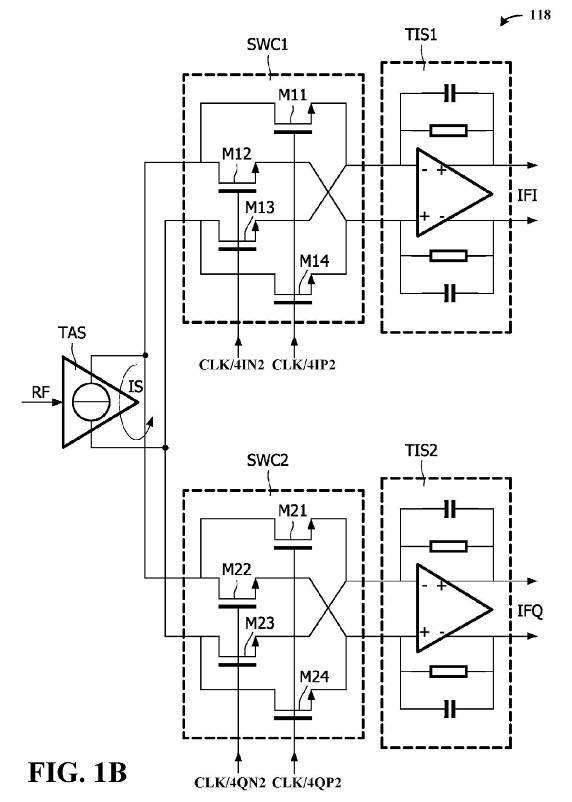
EP2363952
Balanced passive mixer arrangement with two frequency changers located in different paths
This place does not cover:
Circuits for superheterodyne receivers on system level |
In this place, the following terms or expressions are used with the meaning indicated:
Q/I | quadrature / in-phase |
Attention is drawn to the following places, which may be of interest for search:
Homodyne or synchrodyne circuits for amplitude demodulation using two quadrature channels | |
Angle demodulation by converting the oscillations into two quadrature related signals | |
N-path filters |
This place covers:
Example:
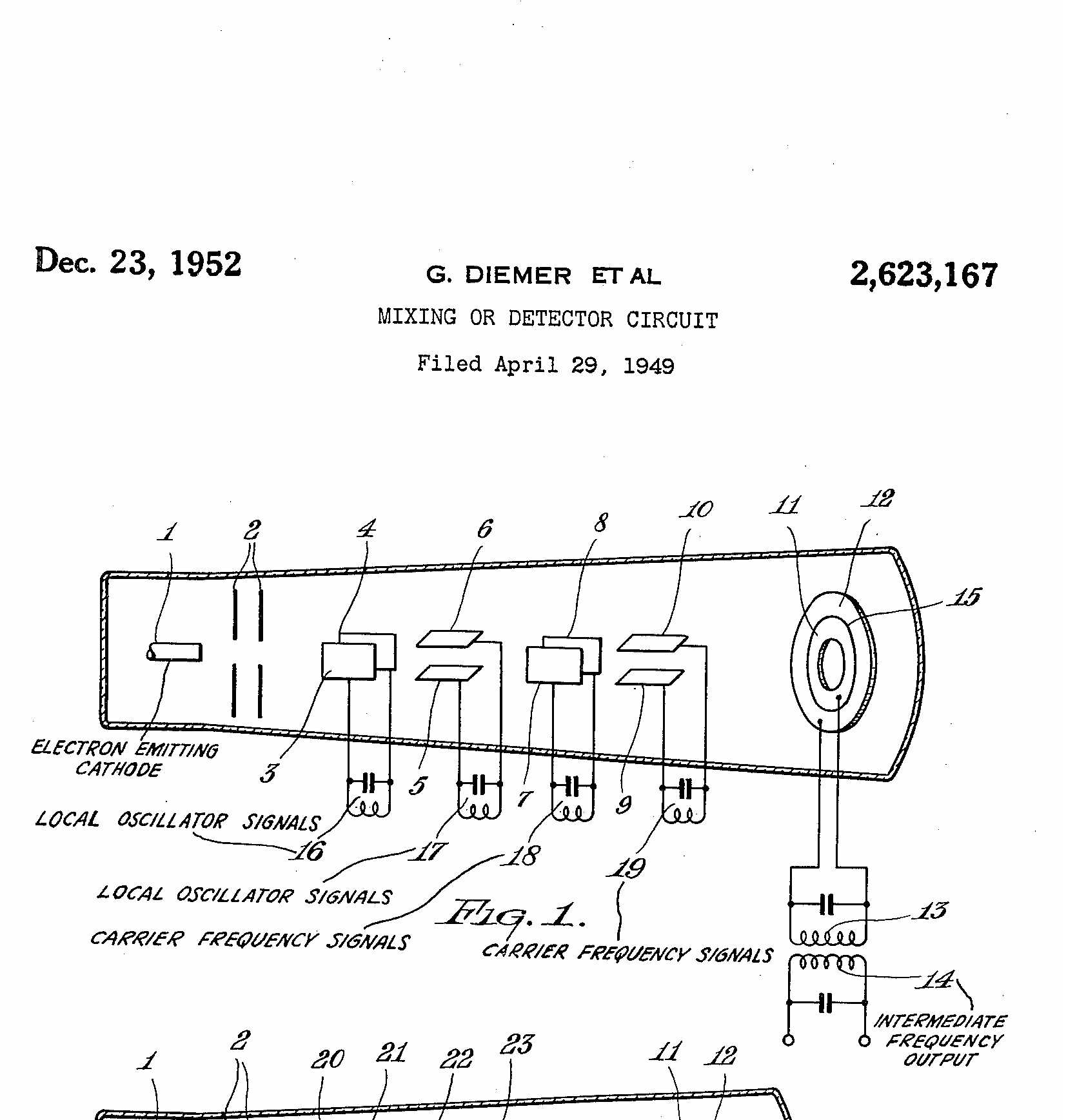
US2623167:
Mixing of a signal ("carrier") frequency with a local oscillator frequency to obtainan intermediate frequency by means of a discharge tube.
This place does not cover:
Transference of modulation by means of transit-time tubes |
This place covers:
This place does not cover:
Devices or arrangements for demodulating light transferring the modulation of modulated light or for changing the frequency of light |
Further classification information:
This place covers:
Example:
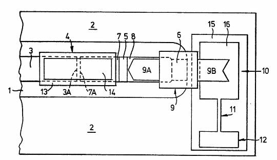
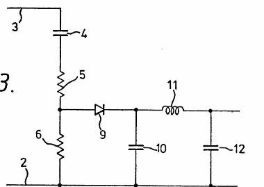
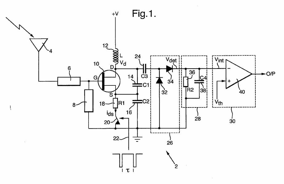
GB2128827
Demodulation using a microwave detector including a transmission line (11) as distributed inductance
This place covers:
Example:
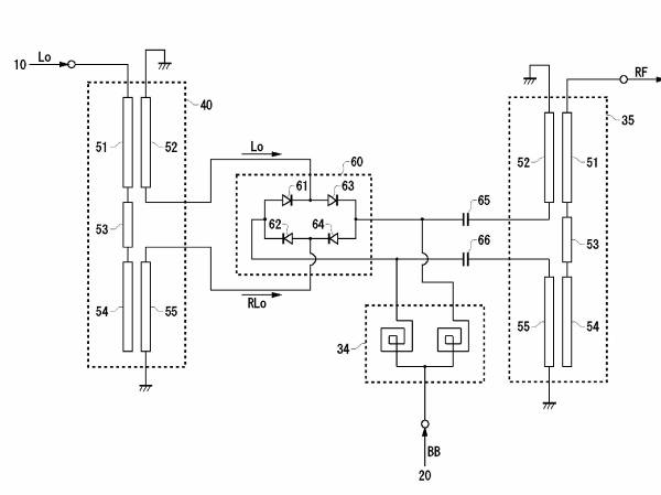
WO2009054095
Transference of modulation using a mixer based on diodes and microstrip lines (51, 54) as distributed inductances
This place does not cover:
Diodes mounted on a stripline circuit located in a hollow waveguide |
This place does not cover:
Using a combination of bipolar transistors and field effect transistors |
This place does not cover:
Using a combination of bipolar transistors and field effect transistors |
This place covers:
Super-regenerative demodulator circuits for amplitude modulation H03D 11/02
Super-regenerative demodulator circuits for angle modulation H03D 11/06
Attention is drawn to the following places, which may be of interest for search:
Applications in responders |
In this place, the following terms or expressions are used with the meaning indicated:
Regenerative receiver; Super-regenerative receiver | A regenerative receiver is a receiver that uses feedback around an active device in a bandpass circuit, causing it to operate on the verge of oscillation. The active device may then provide high amplification of an RF signal in a receiver circuit that needs few components. In a super-regenerative receiver, the oscillation grows at the desired RF frequency and a lower frequency oscillation (within the same stage or from a second oscillator stage) periodically interrupts or "quenches" the main RF oscillation. This may occur at an ultrasonic rate. |
This place covers:
Example:
GB2343571
Super regenerative demodulator
This place covers:
Phase or frequency comparators
- in which a pulse counter is used followed by a conversion into an analog signal H03D 13/001
- in which both oscillations are converted by logic means into pulses which
- are applied to filtering or integrating means H03D 13/003
- in which one of the oscillations is, or is converted into, a signal having a special waveform, e.g. triangular H03D 13/005
- by analog multiplication of the oscillations or by performing a similar analog operation on the oscillations H03D 13/007
Example:
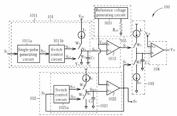
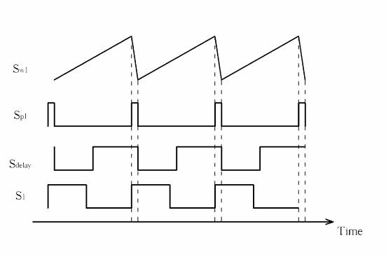
US2008122491
Frequency comparator in which one signal (S1) is converted into a triangular waveform (Sw1) and compared with an internal oscillation (S2)
This place does not cover:
Arrangements for measuring phase angle between a voltage and a current or between voltages or currents | |
Phase-discriminators with yes/no output |
Attention is drawn to the following places, which may be of interest for search:
Phase locked loops; frequency or phase detectors or comparators therein |
This place covers:
Demodulation or transference of signals modulated on a sinusoidal carrier or on electromagnetic waves that does not comply with other groups of this subclass.
This place does not cover:
Demodulation of amplitude-modulated oscillations | |
Demodulation of angle-, frequency-or phase- modulated oscillations | |
Circuits for demodulating amplitude-modulated or angle-modulated oscillations at will | |
Transference of modulation from one carrier to another, e.g. frequency-changing | |
Demodulation or transference of modulation of modulated electromagnetic waves | |
Super-regenerative demodulator circuits by means of semiconductor devices having more than two electrodes | |
Circuits for comparing the phase or frequency of two mutually-independent oscillations |
This place covers:
Particular circuit elements of demodulators H03D 2200/0001.
Functional aspects of demodulators H03D 2200/0041.
This place does not cover:
Homodyne or synchrodyne circuits for amplitude demodulation using quadrature channels | |
Angle demodulation by converting the oscillations into two quadrature related signals | |
Multiple frequency changing with at least two frequency changers being located in different paths |