CPC Definition - Subclass F28B
This place covers:
As specified in the head notes of the field F28, an apparatus using heat exchange for specific purposes is classified either in subclass F28B or in the appropriate subclasses of, for example, classes F22, F24, F25, F26, or F27; or in F28C, F28D.
The subclass F28B covers heat exchangers for converting steam or vapour from its gaseous to its liquid state: typically, a steam condenser has a function to condense exhausted steam from a steam turbine for reuse in the cycle. Steam condensers are widely used in steam turbine power plants. Usually, steam condensers are operated at a pressure below atmospheric pressure, to increase the plant efficiency.
However, F28B does not cover condensers used for separation, nor condensers for refrigeration systems.
In this subclass, the condenser is not characterised by a mixture of vapours to be separated, nor by a separation process, nor by a specific cooperation with steam engine plants or refrigeration systems:
- in the subclass B01D, condensers are involved in a process of separating chemical compounds of a mixture of at least 2 vapours, or a vaporised mixture or solution, e.g. vaporised sea water (the term "vapours" is in the plural);
- in the subclass F25J, condensers are also involved in separating processes , but operates under pressure and cryogenic temperatures of liquified gaseous mixtures;
- in the subclass F25B, condensers are used in cooling cycles and are characterised by features related to the refrigerant, e.g. refrigerant subcooler or receiver;
- in the subclass F01K, condensers are used in steam enginer plants and are characterised by features related to the cycle, e.g. Rankine cycle;
This place does not cover:
Condensation of vapours; recovering volatile solvents by condensation | |
Separation of gases or vapours | |
Drying gases or vapours | |
Condensation during pre-treatment of gases prior to electrostatic precipitation of dispersed particles | |
Purifying combustible gases containing carbon monoxide by cooling to condense non-gaseous materials | |
Condensing arrangements in domestic laundry driers | |
Plants characterised by condensers arranged to co-operate with engines | |
Plants characterised by engines being structurally combined with condensers | |
Fluid heaters having heat-generating means specially adapted for extracting latent heat from flue gases by means of condensation | |
Condensers for refrigeration systems | |
Processes or apparatus for liquefying gases or gaseous mixtures | |
Separating the constituents of gaseous mixtures involving the use of liquefaction by partial condensation |
This place covers:
Indirect contact condensers, also called surface condensers, e.g. using liquid as cooling medium or using air as cooling medium.
Liquid cooled condensers are classified in F28B 1/02
Example of a water cooled condenser: US 6128901 A
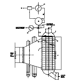
Steam from a low pressure turbine enters a tube and shell condenser through the steam inlet (1) at the top of the condenser and is distributed throughout the shell side. Cooling water is pumped through water inlet (2) in the inlet water box (3) and is distributed throughout the tubes in the tube bundles
Air cooled condensers are classified in F28B 1/06
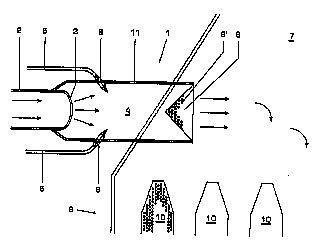
Example of an air cooled condenser: US 2010263840 A
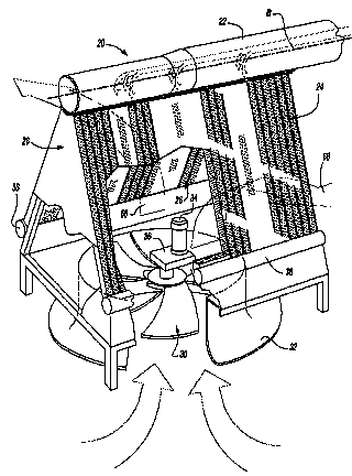
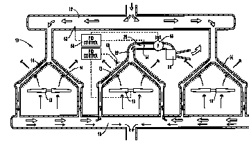
The condenser (20) includes a steam delivery manifold (22), first (24) and second (26) set of bundles of elongated tubes, which are supported on a tent-shaped or V-shaped frame structure (28). The condenser(20) further includes an axial fan (30) directing ambient air upwardly through the first and second sets of tubes (24 ,26).
This place covers:
Direct contact condensers
Direct contact condensers, in which a cooling liquid is injected into the steam are classified in F28B 3/04
Example: US 3834133 A
Water introduced into the partition (20) via the pipes (14,16) is sprayed through the openings (22) outwardly across the housing (10) and in the path of the steam passing therethrough. Due to the resulting transfer of heat from the steam to the water, steam will be condensed, with the mixture of water and condensate falling into a well (24).
Direct contact condensers, in which steam is injected into the cooling liquid are classified in F28B 3/06
Example: US 4304198 A
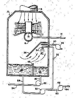
Steam is passed through a blow-off pipe (11) into a closed vessel (14) having a water space (12) and a gas space (13). A nest of heat exchanger tubes (15) extends through the water space (12) in a heat transfer relationship to cool the water space
Attention is drawn to the following places, which may be of interest for search:
Direct contact heat exchangers |
This place covers:
Condensers with cooling by both indirect and direct contact with a cooling medium.
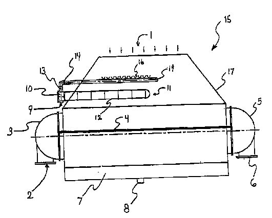
Example: US 6189871 B
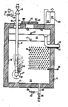
In the cooling chamber (4) are nozzles (6) which inject cool condensate in the form of water drops into the chamber. At the end of the cooling chamber (4), the steam passes through the orifices of a perforated diaphragm (8) which brings about a regular distribution of the cooled steam over the cooling tubes in the tube bundles (10).
This place covers:
Combination of condensers.
Example: US 4301861 A
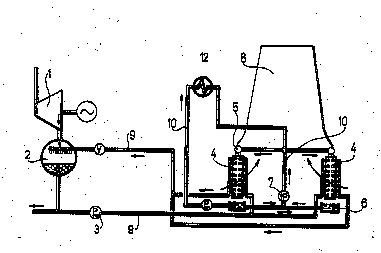
The duct (10) has a first branch (12) leading to a surface type steam condenser (13) in which a portion of the steam is condensed by means of a medium cooled within a wet type cooling tower (16), and a second branch (14) leading to a dry type cooling tower (15) in which the remaining portion of the steam is condensed.
This place covers:
Details of condensers.
Means for feeding steam or vapours are classified in F28B 9/02
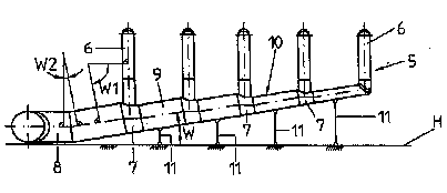
Example: US 2005161094 A
The steam drainage line (5) has air-cooled condensation elements connection to a main steam drainage line (10) via individual branch lines (6), with the cross-section of the main steam drainage line reduced in stages, for reducing pressure losses by allowing gradual reduction in length of branch lines.
Means for feeding cooling liquid are classified in F28B 9/04
Example: US 2003061814 A
The steam surface condenser system (15) includes a make-up water header (19) which introduces make-up water into a condenser steam dome (17). The make-up water header is connected to a make-up water heater bundle (11) and provided with self-adjusting spray nozzles (16). The nozzles spray the make-up water in the direction counter-current to the flow of turbine exhaust steam in the form of fine droplets.
Means for recooling the cooling liquid are classified in F28B 9/06
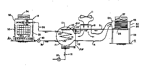
Example: US 3851702 A
The steam of the turbine (1) flows into the mixing condenser (2) where it is condensed by means of injected condensate which is supplied through the pipe conduit (9). The condensed steam is transferred in the form of a condensate by the circulation pump (3) through the lower branch of the pipe conduit (9) to the air cooled surface heat exchangers (4). The warm condensate traverses the pipes of the latter and returns through the upper branch of the pipe conduit (9) into the mixing condenser 2 .
Means for collecting condensates are classified in F28B 9/08
Example: US 6296049 B
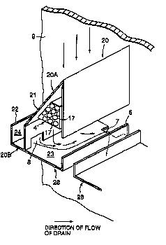
Steam cooling tubes supported by a tube support plate (9) are bisected by a pair of envelopes (28) each of which has a bottom shroud (20B) divided into an inner space (23) and an outer space (24) by a top shroud (20A) which are connected by a circulation opening (8) at the junction. A drain opening (7) is formed at the junction between the tube support plate and the inner space of the bottom shroud.
Means for removing non-condensable gases are classified in F28B 9/10
Example: US 6588499 B
The condenser (10) includes an air ejector system header (22) attached to the top of the D-section condensing tubes (15). Uncondensed steam and inert gas are drawn into and collected in the header at the top of the condensing tubes (15) because a vacuum pump (26) runs continuously thereby lowering the pressure in the air ejector (20) to a point below the pressure of the exhaust steam header (12).
Attention is drawn to the following places, which may be of interest for search:
Steam traps for draining-off liquids from enclosures containing gases or vapours | |
Details of heat exchangers | |
Deaeration systems for heat exchangers | |
Preventing the formation of continuous films of condensate on heat exchangers | |
Draining condensates from heat exchangers | |
Preventing deposits of ice in heat exchangers |
This place covers:
Condenser controlling means, e.g. methods for monitoring condenser performance.
Example: US 5005351 A
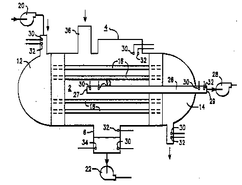
For monitoring condenser operation, the condenser is equipped with temperature sensors (30) and pressure sensors (32), as well as a chemical sensor (34) for permitting measurement of condensate water quality.
Attention is drawn to the following places, which may be of interest for search:
Control arrangements for heat exchangers | |
Control in general |