| CPC F23G 5/32 (2013.01) [F23G 5/24 (2013.01); F23G 5/44 (2013.01); F23G 2200/00 (2013.01); F23G 2203/30 (2013.01); F23G 2206/10 (2013.01); F23G 2207/30 (2013.01); F23G 2900/50214 (2013.01)] | 14 Claims |

|
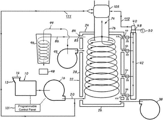
1. A combustor for burning shredded waste material, the combustor comprising:
a first blower configured to entrain the shredded waste material in a primary air stream;
a generally cylindrical combustion chamber comprising spaced first and second end walls, an annular side wall and a central longitudinal axis extending between said first and second end walls, wherein the central longitudinal axis is oriented substantially horizontally, wherein said generally cylindrical combustion chamber defines a first opening in the annular side wall, a second opening in the second end wall and a plurality of third openings in the annular side wall, and wherein said plurality of third openings are spaced apart from said first and second end walls;
a first conduit extending between said first blower and said first opening in the generally cylindrical combustion chamber, wherein said first conduit and said first opening are configured to introduce said primary air stream into said generally cylindrical combustion chamber tangentially to said annular side wall to establish a vortical movement of said waste material between said first and second side walls;
a discharge flue extending through said second opening in said second end wall, wherein said discharge flue is substantially concentric with said central longitudinal axis and wherein an internal end of said discharge flue is spaced axially from said second end wall;
a discharge port with an open end in said combustion chamber adjacent the inner surface of said annular side wall, wherein said discharge port is substantially tangential to said annular side wall near the bottom of said combustion chamber;
a second blower configured to produce a secondary air stream;
a second conduit extending between said second blower and the plurality of third openings in the annular side wall, wherein said second conduit and said plurality of third openings are configured to maintain the vortical movement of said waste material between said first and second side walls, wherein a fourth opening is positioned substantially opposite from the discharge port, wherein the annular side wall of the combustion chamber defines a gutter cut into a bottom surface of the annular side wall of the chamber along a horizontal line extending between said discharge port and the fourth opening, wherein the horizontal line is perpendicular to the central longitudinal axis, and wherein the second conduit extends between said second blower and the fourth opening;
a plurality of first dampers configured to vary the flow of the secondary air stream through each of the plurality of third openings;
a temperature sensor configured to determine a temperature within said combustion chamber; and
a first controller configured to adjust the plurality of first dampers in response to variations of the temperature determined by the temperature sensor.
|