| CPC H05K 7/20263 (2013.01) [G06F 1/20 (2013.01); H05K 7/20272 (2013.01); G06F 2200/201 (2013.01)] | 16 Claims |

|
1. An expansion card assembly, comprising:
an interface card;
a liquid-cooling device, comprising:
a liquid block, in thermal contact with the interface card; and
a radiator, comprising:
a first tank,
a second tank, and
a heat dissipation channel structure,
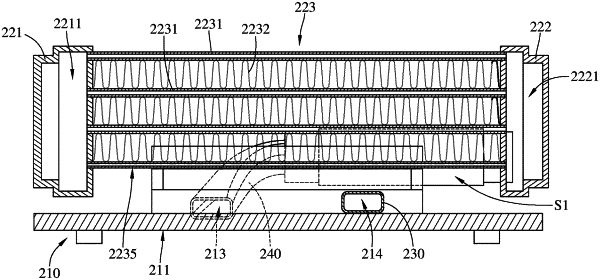
wherein the first tank has a first chamber, the second tank has a second chamber, the heat dissipation channel structure comprises a plurality of liquid transmission components, the first chamber of the first tank and the second chamber of the second tank are respectively connected to two opposite sides of the heat dissipation channel structure, each of the plurality of liquid transmission components of the heat dissipation channel structure has an end in fluid communication with the first chamber of the first tank and another end in fluid communication with the second chamber of the second tank, each of the plurality of liquid transmission components has a hollow part therein as being in fluid communications with the first chamber and the second chamber, the first chamber and the second chamber are in fluid communication with the liquid block to form a cooling cycle, the first tank and the second tank protrude from an edge of the heat dissipation channel structure located close to the interface card, the first tank, the second tank, and the heat dissipation channel structure together surround an accommodation space, the liquid block is at least partially located in the accommodation space, and the liquid block has two opposite sides respectively spaced apart from the first tank and the second tank; and
an airflow generator, located adjacent to the radiator, wherein the airflow generator is configured to generate an airflow flowing towards the heat dissipation channel structure of the radiator.
|