| CPC H02M 7/5395 (2013.01) | 5 Claims |

|
1. A power converter comprising:
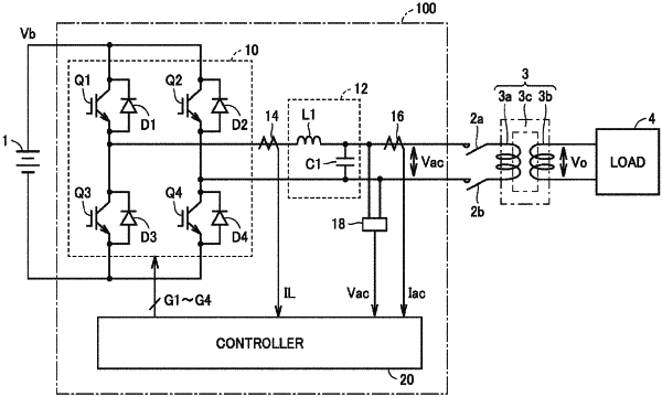
an inverter that converts a DC voltage at a DC side to an AC voltage and outputs the AC voltage from an AC side, the AC side of the inverter being connected to a load via a transformer, the transformer supplying, to the load, the AC voltage that is output from the AC side;
a controller that controls the inverter;
a first current detector that detects primary winding current of the transformer;
a second current detector that detects output current of the inverter; and
a voltage detector that detects the AC voltage that is output from the AC side,
the controller including:
a voltage control unit that generates an AC current command value by adding a feed-forward term to a result of a control calculation that is performed for reducing a difference of a value of the AC voltage detected by the voltage detector, with respect to an AC voltage command value, the feed-forward term being determined by multiplying, by a gain, a value of the primary winding current detected by the first current detector;
a current control unit that generates an inverter control command value by a control calculation that is performed for reducing a difference of a value of the output current of the inverter detected by the second current detector, with respect to the AC current command value; and
a PWM circuit that performs PWM control of the inverter by comparing the inverter control command value with a predetermined carrier wave to generate a control signal for the inverter, wherein
when exciting inrush current is detected in a value of the primary winding current detected by the first current detector, the voltage control unit sets the gain smaller than the gain when the exciting inrush current is not detected.
|