| CPC H02G 1/04 (2013.01) [B66F 3/08 (2013.01); B66F 2700/09 (2013.01)] | 4 Claims |

|
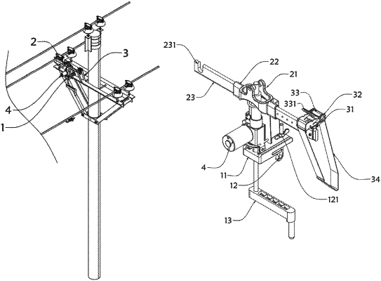
1. An electrified wire lifting device, comprising:
a locking assembly (1) fixed on a bracket of an electric pole for integrally fixing the device;
a connecting assembly (2) having one end used for clamping a wire and the other end locked and fixed on the bracket of the electric pole by means of an adjusting assembly (3); and
a lifting assembly (4) mounted on the top of the locking assembly (1) for performing a lifting movement on the connecting assembly (2) at the top;
wherein the locking assembly (1) comprises a support plate (11), a hook (12) is provided on one side of the bottom of the support plate (11) for hanging on the bracket of the electric pole, a top end of the hook (12) passes through the support plate (11) and is provided with a threaded end, and a positioning nut (121) is mounted outside the threaded end;
the lifting assembly (4) comprises a lifting motor (41) having an output end provided with a worm (411), a worm wheel (42) is provided outside the worm (411), a screw rod (43) is tightly welded on the top of the worm wheel (42), a second lifting rod (44) is provided outside the screw rod (43), threads are provided inside the second lifting rod (44), the screw rod (43) is in threaded connection with the second lifting rod (44), and a stopper sleeve (45) is tightly welded outside the second lifting rod (44); a stopper (451) is mounted on one side of the stopper sleeve (45), a fixed sleeve (46) is provided outside the bottom of the stopper sleeve (45) in a sleeving manner, and the shape of the inner wall of the fixed sleeve (46) is the same as the shape of the outer wall of the stopper sleeve (45), and is used for limiting the stopper sleeve (45) to prevent the same from rotating;
the connecting assembly (2) comprises a movable piece (21) having one end connected with a first lifting rod (23) for lifting the wire by means of a socket (22), and the top of the outer end of the first lifting rod (23) is provided with a recess (231) for clamping the wire; and
the adjusting assembly (3) comprises a fixed seat (31) mounted on the other side of the movable piece (21), a rotating shaft (33) is provided on the fixed seat (31), a belt (34) is connected to the outside of the rotating shaft (33) and bound to the bracket of the electric pole, and the other end is connected to the outside of the fixed seat (31), both ends of the rotating shaft (33) pass through the side wall of the fixed seat (31) and are mounted with a toothed disc (32), outer walls at both ends of the fixed seat (31) are each provided with a bayonet, and the outside of the fixed seat (31) is provided with an adjusting handle (331) having one end capable of catching the bayonet of both ends of the fixed seat (31) and the bayonet of the toothed disc (32) to prevent the rotating shaft (33) from rotating.
|