| CPC H01M 10/613 (2015.04) [A62C 3/16 (2013.01); H01M 10/627 (2015.04); H01M 10/63 (2015.04); H01M 10/6552 (2015.04); H01M 10/6563 (2015.04); H01M 10/6568 (2015.04); H01M 10/667 (2015.04); H01M 2220/10 (2013.01)] | 7 Claims |

|
1. An apparatus for a fire suppressant system, the apparatus comprising:
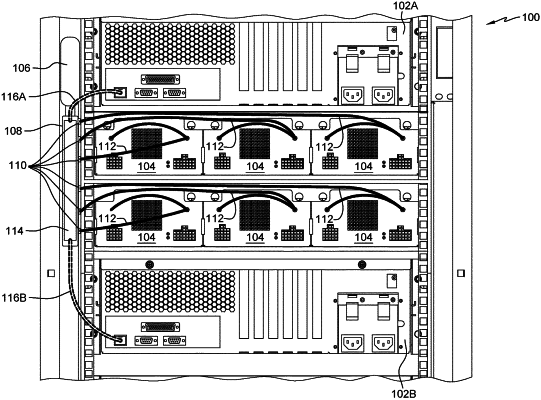
an integrated battery feature, a manifold, a conduit, and a control card, wherein the integrated battery feature includes a plurality of battery cells in an enclosure;
a first end of the conduit coupled to a control valve on the manifold and a second end of the conduit coupled to the integrated battery feature;
the control card configured to open the control valve on the manifold, wherein the control valve is configured to release a cooling fluid into the enclosure;
a fluid manifold conduit and a radiator cooling unit valve, wherein a first end of the fluid manifold conduit is coupled to the manifold and a second end of the fluid manifold conduit is coupled to the radiator cooling unit valve; and
the radiator cooling unit valve is configured to divert the cooling fluid to the fluid manifold conduit in a first configuration, wherein the cooling fluid is a fire suppressant.
|