| CPC G02B 6/3885 (2013.01) [G02B 6/3847 (2013.01); G02B 6/3882 (2013.01)] | 15 Claims |

|
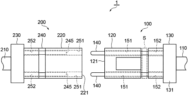
1. An optical connection structure comprising:
a plurality of first optical fibers each extending in a longitudinal direction;
a plurality of second optical fibers each extending in the longitudinal direction;
a first optical connector including a first front end surface and a plurality of first fiber holes opening on the first front end surface, the first optical connector holding the plurality of first optical fibers; and
a second optical connector including a second front end surface and a plurality of second fiber holes opening on the second front end surface, the second optical connector holding the plurality of second optical fibers,
wherein the first optical connector is configured such that each of first distal end portions of the plurality of first optical fibers respectively accommodated in the plurality of first fiber holes protrudes from the first front end surface outside of the plurality of first fiber holes when the first optical connector and the second optical connector are connected to each other,
wherein each of the first distal end portions protruding from the first front end surface is inserted into a corresponding second fiber hole of the plurality of second fiber holes of the second optical connector,
wherein the second optical connector is configured such that each of second distal end portions of the plurality of second optical fibers is moved rearward inside the plurality of second fiber holes due to each of the first distal end portions respectively inserted into the plurality of second fiber holes when the first optical connector and the second optical connector are connected to each other, and
wherein the plurality of first optical fibers and the plurality of second optical fibers are optically coupled to each other inside the plurality of second fiber holes when the first optical connector and the second optical connector are connected to each other.
|