| CPC G01F 1/662 (2013.01) [G01F 15/06 (2013.01); G01K 13/02 (2013.01); H05K 1/181 (2013.01); H05K 2201/10098 (2013.01); H05K 2201/10128 (2013.01)] | 8 Claims |

|
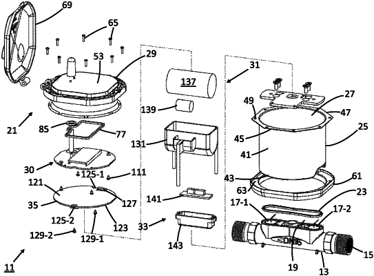
1. A flow meter, comprising:
(a) a flow tube shaped to define an internal passageway;
(b) a set of transducers coupled to the flow tube in fluid communication with the internal passageway; and
(c) a core module coupled to the flow tube, the core module comprising,
(i) an enclosure shaped to define an interior cavity, wherein the enclosure is a cylindrical housing with a continuous sidewall, a partially enclosed bottom end, and an open top end,
(ii) a partition mounted within the interior cavity of the enclosure, the partition separating the interior cavity into an upper compartment and a lower compartment,
(iii) a printed circuit board (PCB) assembly in electrical communication with the set of transducers, the PCB assembly being mounted in the enclosure within the upper compartment of the interior cavity, the PCB assembly comprising,
(A) a printed circuit board having a top surface, a bottom surface and at least one transverse potting hole,
(B) a digital display mounted on the top surface of the printed circuit board,
(C) an antenna mounted on the top surface of the printed circuit board, and
(D) an electrical connector mounted on the bottom surface of the printed circuit board,
(iv) a power supply assembly in electrical communication with the PCB assembly and the set of transducers, the power supply assembly being mounted in the enclosure within the lower compartment of the interior cavity,
(v) a top cover mounted on the open top end of the enclosure, the top cover comprising,
(A) a planar top wall having a top surface and a bottom surface, the planar top wall comprising,
(I) a display window,
(II) a pair of spaced apart sidewalls projecting out from the bottom surface immediately around the periphery of the display window, the pair of sidewalls defining a narrow groove therebetween,
(III) a hollow conical projection extending orthogonally out from the top surface,
(IV) wherein the PCB assembly is secured to the bottom surface of the top wall of the top cover such that the digital display directly aligns within the display window and the antenna protrudes into the conical projection,
(V) wherein the partition is mounted onto the top cover over the PCB assembly,
(B) a cylindrical collar projecting orthogonally out from the bottom surface of the planar top wall, and
(C) a flange projecting radially outward from the planar top wall, the flange being shaped to define a plurality of thru-holes, and
(vi) first and second seals, the first seal being inserted within the narrow groove in the top wall of the top cover to create a watertight seal between the top cover and the PCB assembly around the digital display, the second seal being disposed around the antenna to create a watertight seal between the top cover and the PCB assembly around the antenna.
|