| CPC E06C 9/04 (2013.01) [E02D 29/122 (2013.01); F16B 13/068 (2013.01); F16B 13/0833 (2013.01); F16B 13/0858 (2013.01); F16B 21/08 (2013.01); F16B 21/086 (2013.01)] | 20 Claims |
|
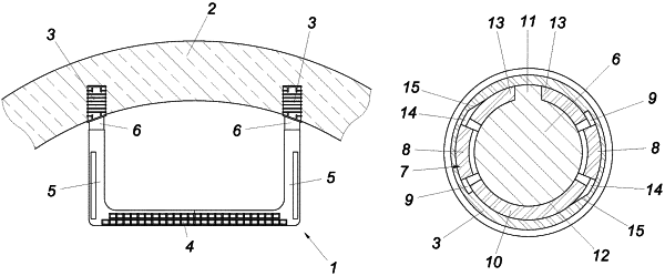
1. A device for fastening a step iron in a concrete wall, said device comprising:
two anchor sleeves being supported and securingly moulded in the concrete wall;
the step iron being generally U-shaped and having two parallel anchor bolts each being inserted in and form-fittingly accommodated by a respective one of the anchor sleeves, each of the anchor sleeves and a respective one of the anchor bolts accommodated thereby forming a respective set of coupling parts, and
a detent assembly between the coupling parts of one of the sets that includes at least one detent tongue that is sprung in a radial direction and is supported on one of the coupling parts of the set, and structure on the other coupling part of the set defining a detent recess that receives the detent tongue, and
wherein said other coupling part has a guide surface that is engageable with the detent tongue and is inclined in a circumferential direction and extending in the radial direction over an engagement depth of the detent tongue, and said guide surface adjoins the detent recess at least in the circumferential direction.
|
|
17. A device for fastening a step iron in a concrete wall, said device comprising:
two anchor sleeves being supported in the concrete wall;
the step iron being generally U-shaped and having two parallel anchor bolts each form-fittingly accommodated by a respective one of the anchor sleeves, each of the anchor sleeves and a respective one of the anchor bolts accommodated thereby forming a respective set of coupling parts, and
a detent assembly between the coupling parts of one of the sets that includes at least one detent tongue that is sprung in a radial direction and is supported on one of the coupling parts of the set, and structure on the other coupling part of the set defining a detent recess that receives the detent tongue, and
wherein a guide surface engageable with the detent tongue and being inclined in a peripheral direction and extending in the radial direction over an engagement depth of the detent tongue adjoins the detent recess at least in the peripheral direction; and
wherein the at least one detent tongue is resilient and is supported on an open spring ring inserted non-rotatably into a peripheral groove of said one of the coupling parts; and
wherein the other coupling part has a second detent recess, and the open spring ring has another detent tongue arranged diametrically opposed to the detent tongue and each of the detent tongues engages in a respective one of said detent recesses.
|