| CPC B25J 5/00 (2013.01) [B25J 19/0091 (2013.01); B25J 19/02 (2013.01)] | 6 Claims |

|
1. A foot structure of a legged mobile robot, which is a structure of a foot provided at a lower end of a movable leg of the legged mobile robot, the foot structure comprising:
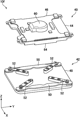
an instep member that is connected to the movable leg and receives a load of the legged mobile robot;
a sole member that is deployed under the instep member and contacts with a walking surface;
an elastic supporting member that is attached to the sole member and elastically supports the instep member against the load; and
a plurality of sensor mechanisms that detect floor reaction force at positions different from each other on the sole member,
wherein:
each of the plurality of sensor mechanisms includes:
a force sensor provided on one of the instep member and or the sole member, and
a sensor pressing member that:
is an elastic body having a rigidity lower than that of the elastic supporting member,
exerts a pressing force to the force sensor, according to a change in distance between the instep member and the sole member, and
has a supporting point deployed on the other of the instep member or the sole member at a position not vertically aligned with the force sensor such that the force sensor is closer to an outer edge of the foot structure than the supporting point,
the force sensor is attached to the instep member,
the supporting point of the sensor pressing member is deployed on the sole member,
each of the plurality of sensor mechanisms is provided at an angular portion corresponding to each of vertices of a rectangular shape including sides extending along a forward and rearward direction of the foot and sides extending along a leftward and rightward direction of the foot,
the sensor pressing member is a leaf spring extending along a diagonal line of the rectangular shape, and
the sole member has, on the diagonal line, a spring mount to which the sensor pressing member is attached, as the supporting point thereof.
|