| CPC B25B 21/023 (2013.01) [B25F 5/001 (2013.01)] | 13 Claims |

|
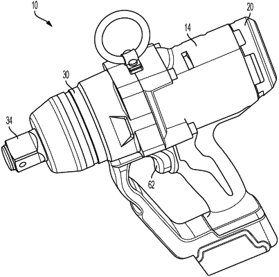
1. A rotary impact tool comprising:
a motor housing;
an electric motor supported in the motor housing;
a drive assembly for converting a continuous torque input from the motor to consecutive rotational impacts upon a workpiece, the drive assembly including
an anvil including an anvil lug, and
a hammer that is both rotationally and axially movable relative to the anvil, the hammer including a hammer lug for imparting the consecutive rotational impacts upon the anvil lug;
a printed circuit board assembly including an anvil sensor that is configured to detect rotation of the anvil, wherein the printed circuit board assembly is spaced from the anvil to define an axial gap therebetween;
an impact housing extending from a front end of the motor housing, wherein the drive assembly is at least partially supported within the impact housing, wherein the anvil includes a drive end extending from the impact housing; and
a bushing coupled to the impact housing and surrounding the anvil.
|