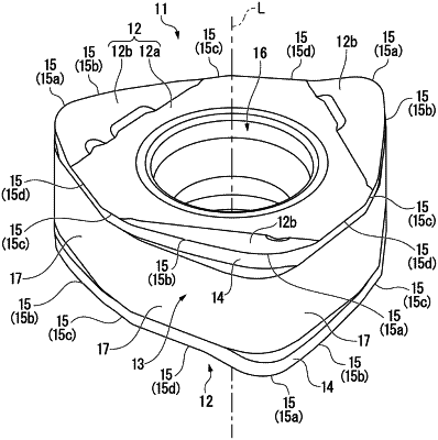
| CPC B23C 5/06 (2013.01) [B23C 5/202 (2013.01); B23C 2200/0483 (2013.01); B23C 2200/208 (2013.01); B23C 2200/28 (2013.01); B23C 2200/293 (2022.02)] | 9 Claims |

|
1. A cutting insert, comprising:
a polygonal plate-shaped insert main body having:
two polygonal surfaces, one of the two polygonal surfaces serving as a seating surface when the other of the two polygonal surfaces serves as a rake face,
a side surface located around the two polygonal surfaces, the side surface having
a flank which intersects the rake face, and
a plurality of planar restriction surfaces parallel to an insert center line passing through a respective center of the two polygonal surfaces, an insert mid-plane perpendicular to the insert center line intersects the plurality of planar restriction surfaces, and
a cutting edge formed in an intersection ridgeline portion between the rake face and the flank,
wherein the insert main body has a rotationally symmetrical shape with respect to the insert center line passing through the respective center of the two polygonal surfaces, and the two polygonal surfaces have a same shape,
wherein the cutting edge includes edge sets, and each of the edge sets includes:
a corner cutting edge, a major cutting edge, and a wiper cutting edge,
the corner cutting edge is located in a corner portion of the polygonal surface serving as the rake face,
the major cutting edge extends from, and is directly connected to, one end of the corner cutting edge, and
the wiper cutting edge extends from one end of the major cutting edge at a first internal obtuse angle in a plan view of the polygonal surface serving as the rake face,
wherein each of the edge sets further includes a minor cutting edge at an other end of the corner cutting edge opposite the one end of the corner cutting edge, and the minor cutting edge of one edge set and the wiper cutting edge of an adjacent edge set, directly connected to the minor cutting edge of the one edge set, form a second internal obtuse angle,
wherein the flank has clearance angles, the clearance angles are formed by the flank and a respective straight line parallel to the insert center line and passing through the cutting edge,
wherein in each of the edge sets, the flank includes:
a first region spanning the major cutting edge,
a second region including the corner cutting edge and part of the minor cutting edge extending from the other end of the corner cutting edge, and
a third region in a remaining range of the minor cutting edge extending from an end of the second region, the third region being further from the corner cutting edge than the second region,
wherein in the first region in a direction from a bisector of the wiper cutting edge toward the one end of the corner cutting edge, the clearance angles gradually decrease to a negative angle value from a first positive angle value,
wherein in the second region, the clearance angles gradually increase from the negative angle value to a second positive angle value,
wherein in the third region, the clearance angles have a respective positive value and vary so that a change rate of the clearance angles in the third region is lower than a respective change rate of the clearance angles in the first region and the second region.
|