| CPC H03F 1/565 (2013.01) [H03F 3/195 (2013.01); H03F 3/245 (2013.01); H03F 3/72 (2013.01); H03F 2200/318 (2013.01); H03F 2200/451 (2013.01)] | 19 Claims |

|
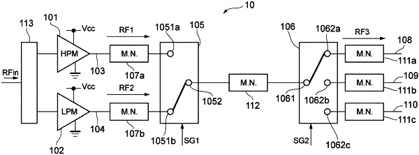
1. A power amplifier circuit comprising:
a first amplification path including at least one first power amplifier configured to amplify an input signal to generate a first signal when in a first power mode;
a second amplification path including at least one second power amplifier configured to amplify the input signal to generate a second signal when in a second power mode;
a first switching circuit including a plurality of first input terminals and a first output terminal, one of the plurality of the first input terminals being connected to the first amplification path, another one of the plurality of the first input terminals being connected to the second amplification path, the first switching circuit being configured to electrically connect either the first amplification path or the second amplification path and the first output terminal to each other in response to a first control signal indicating either the first power mode or the second power mode;
a second switching circuit including a second input terminal and a plurality of second output terminals and configured to electrically connect the second input terminal and any one of the plurality of the second output terminals to each other in response to a second control signal; and
a first matching circuit configured to electrically connect the first output terminal and the second input terminal to each other and achieve impedance matching between the first output terminal and the second input terminal.
|