| CPC H02P 23/14 (2013.01) [G06F 1/04 (2013.01); H03H 17/02 (2013.01); H03K 5/24 (2013.01); H03M 1/12 (2013.01)] | 14 Claims |

|
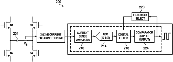
1. A ripple counter, comprising:
a current sense amplifier having an input and an output;
an analog-to-digital converter (ADC) having an input coupled to the output of the current sense amplifier and an output;
a digital filter having a first input coupled to the output of the ADC, a second input and an output;
a digital comparator circuit having an input coupled to the output of the digital filter and an output; and
a clock generator having an input coupled to the output of the digital comparator circuit and an output coupled to the second input of the digital filter.
|
|
5. A DC motor control system, comprising:
a DC motor having rotor windings;
a current sense amplifier having an input electrically coupled to the rotor windings and an output;
an analog-to-digital converter (ADC) having an input coupled to the output of the current sense amplifier and an output;
a digital filter having a first input coupled to the output of the ADC, a second input and an output;
a digital comparator circuit having an input coupled to the output of the digital filter and an output; and
a clock generator having an input coupled to the output of the digital comparator circuit and an output coupled to the second input of the digital filter.
|
|
9. A DC motor control system, comprising:
a DC motor having rotor windings coupled to commutator segments arranged on a rotor, wherein the commutator segments are electrically coupled via brushes to a DC voltage supply;
a current sense amplifier having an input electrically coupled to the rotor windings and having an output;
an analog-to-digital converter (ADC) having an input coupled to the output of the current sense amplifier and an output;
a digital filter having a first input coupled to the output of the ADC, a second input and an output;
a digital comparator circuit having an input coupled to the output of the digital filter and an output; and
a clock generator having an input coupled to the output of the digital comparator circuit and an output coupled to the second input of the digital filter.
|