| CPC H02M 1/0009 (2021.05) [H02M 3/158 (2013.01)] | 18 Claims |
|
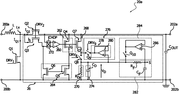
1. A sensor system, comprising:
a power field effect transistor (FET) comprising first and second conduction terminals defining a current path, and a gate terminal configured to receive a drive signal; and
a sensor circuit configured to monitor a current flowing through said power FET;
wherein said sensor circuit comprises:
a sense resistance; and
a regulator circuit configured to:
when the drive signal applied to said gate terminal is set to turn the power FET off, set a first current flowing through the sense resistance to zero; and
when the drive signal applied to said gate terminal is set to turn the power FET on, regulate said first current flowing through the sense resistance such that a voltage drop at the sense resistance corresponds to a voltage drop between said first and second conduction terminals of said power FET;
a measurement circuit configured to provide a second current corresponding to said first current or being proportional to said first current;
a resistor;
a first electronic switch configured to selectively apply said second current to said resistor as a function of a first control signal;
a low pass filter configured to generate a low-pass filtered signal by filtering a voltage at said resistor resulting from the application of said second current to said resistor;
a voltage follower configured to generate a replica of said low-pass filtered signal;
a second electronic switch configured to selectively apply said replica of said low-pass filtered signal to said resistor; and
a control circuit configured to:
when said power FET is on, close said first electronic switch and open said second electronic switch to generate the voltage at said resistor proportional to an instantaneous value of said current flowing through said power FET; and
when said power FET is off, open said first electronic switch and close said second electronic switch to generate the voltage at said resistor corresponding to said low-pass filtered signal, and wherein said low-pass filtered signal is proportional to an average value of said current flowing through said power FET during periods when said power FET is on.
|