| CPC H02K 3/522 (2013.01) [F25B 1/00 (2013.01); F25B 31/004 (2013.01); F25B 31/006 (2013.01); H02K 5/207 (2021.01); H02K 11/33 (2016.01); H02K 21/16 (2013.01); H02K 2203/06 (2013.01)] | 3 Claims |

|
1. An electric compressor comprising:
a housing;
a drive shaft;
an electric motor configured to rotate the drive shaft;
a compression portion configured to be driven by the drive shaft to compress refrigerant; and
an inverter including a first phase, a second phase, and a third phase that are electrically connected to the electric motor to form a three-phase alternating current, the inverter controlling driving the electric motor,
wherein the housing includes a motor chamber that houses the electric motor and through which refrigerant passes,
wherein the first phase includes a first inverter-side connection terminal,
wherein the second phase includes a second inverter-side connection terminal,
wherein the third phase includes a third inverter-side connection terminal,
wherein the electric motor includes a stator that is fixed to the housing and disposed in the motor chamber, and a rotor to which the drive shaft is fixed, the rotor being disposed in the stator and rotatable with the drive shaft,
wherein the stator includes:
a stator core that has a tubular shape, a plurality of slots, and extends in a direction of a shaft center of the drive shaft, wherein each slot, among the plurality of slots, is recessed from an inner circumferential surface of the stator core toward an outer circumferential surface of the stator core;
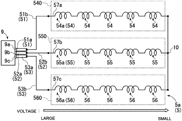
a plurality of first coils formed by winding, to the stator core, a first conductor wire that is electrically connected to the first phase, wherein each first coil, of the plurality of first coils, is formed by a concentrated winding in which the first conductor wire is wound in the slots;
a plurality of second coils formed by winding, to the stator core, a second conductor wire that is electrically connected to the second phase, wherein each second coil, of the plurality of second coils, is formed by a concentrated winding in which the second conductor wire is wound in the slots; and
a plurality of third coils formed by winding, to the stator core, a third conductor wire that is electrically connected to the third phase, wherein each third coil, of the plurality of third coils, is formed by a concentrated winding in which the third conductor wire is wound in the slots;
a first connector, a second connector, and a third connector,
wherein the first coils are connected to each other in series, the second coils are connected to each other in series, and the third coils are connected to each other in series,
wherein one of the first coils that is located electrically closest to the first phase is referred to as a first specific coil, one of the second coils that is located electrically closest to the second phase is referred to as a second specific coil, and one of the third coils that is located electrically closest to the third phase is referred to as a third specific coil,
wherein the first specific coil is connected to the first connector through a first lead wire, the second specific coil is connected to the second connector through a second lead wire, and the third specific coil is connected to the third connector through a third lead wire,
wherein a part of the first connector, a part of the second connector, and a part of the third connector are located below a reference surface in a vertical direction, and a remaining portion, other than the part of the first connector, the part of the second connector, and the part of the third connector, is located above the reference surface in the vertical direction, and
wherein the first specific coil, the second specific coil, and the third specific coil are disposed above the shaft center of the drive shaft.
|