| CPC H02K 24/00 (2013.01) [G01D 5/20 (2013.01); H02K 1/14 (2013.01); H02K 1/165 (2013.01); H02K 11/225 (2016.01)] | 9 Claims |

|
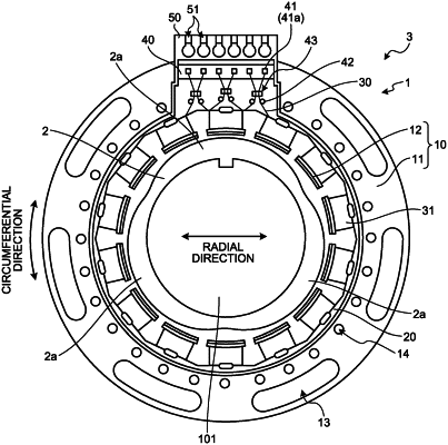
1. A stator structure of a resolver comprising:
a stator core comprising
a main body,
a plurality of teeth extending in a radial direction of the main body and arranged along a circumferential direction of the main body, and
slots formed between the teeth; and
a coil wound around the teeth via an insulator,
wherein the main body has a plurality of holes arranged along the circumferential direction of the main body on an outer peripheral side of the teeth, and
wherein the plurality of holes comprise a first group of holes arranged at a position overlapping with the tooth in the radial direction so as to be close to the root part of the teeth and a second group of holes arranged at a position overlapping with the slots in the radial direction so as to be close to the slots.
|