| CPC H01P 5/12 (2013.01) [H01F 27/2804 (2013.01); H01F 27/29 (2013.01); H01F 27/40 (2013.01); H01G 4/30 (2013.01); H01G 4/40 (2013.01)] | 15 Claims |

|
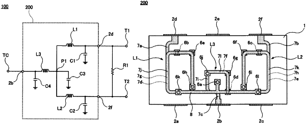
1. A power distribution/coupling circuit comprising:
a common terminal;
a first terminal;
a second terminal;
a first connection point connected to the common terminal;
a first inductor connected between the first connection point and the first terminal;
a second inductor connected between the first connection point and the second terminal;
a first capacitor shunt-connected between an end of the first inductor closer to the first terminal and a ground;
a second capacitor shunt-connected between an end of the second inductor closer to the second terminal and the ground;
a third capacitor shunt-connected between the first connection point and the ground; and
a resistor connected between the first terminal and the second terminal; wherein
the power distribution/coupling circuit is configured to distribute electric power input to the common terminal at the first connection point and output the electric power from the first terminal and the second terminal, or to couple the electric power input to the first terminal and the second terminal at the first connection point and output the electric power from the common terminal; and
the power distribution/coupling circuit further includes a third inductor connected between the common terminal and the first connection point, and a fourth capacitor shunt-connected between an end of the third inductor closer to the common terminal and the ground.
|