| CPC H01B 11/1808 (2013.01) [H01B 11/1856 (2013.01); H01B 13/0167 (2013.01); H01P 3/06 (2013.01); H01R 12/722 (2013.01); H01R 12/75 (2013.01)] | 16 Claims |

|
1. A coaxial cable, comprising:
a continuous signal conductor carrying signals;
a dielectric layer surrounding and in direct contact with the signal conductor; and
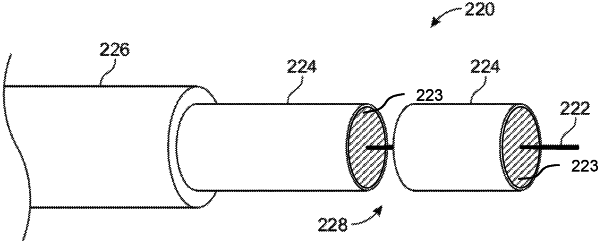
a ground sheath providing a ground return path to the signals carried by the signal conductor, wherein the ground sheath comprises a conductive layer disposed at least partially around the signal conductor such that the dielectric layer is positioned between the ground sheath and the signal conductor, wherein the conductive layer of the ground sheath and the dielectric layer each comprise a single gap separating a first continuous portion and a second continuous portion of the conductive layer and the dielectric layer, the single gap being filled with a material comprising carbon loaded ceramic or mica and dimensioned such that a distance between a first edge of the first continuous portion and a second edge of the second continuous portion is between 20 and 200 microns, thereby creating a capacitance between 0.01 μF and 10 pF in the ground return path to block propagation of direct current (DC) signals in the coaxial cable.
|