| CPC G06K 19/07794 (2013.01) [G06K 19/0723 (2013.01); G06K 19/07771 (2013.01); G06K 19/07786 (2013.01); H01Q 1/2208 (2013.01)] | 19 Claims |

|
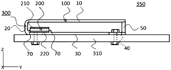
1. An RFID tag device comprising:
an RFID tag; and
a boost antenna, the boost antenna comprising:
a radiation unit that is conductive;
a ground unit that is conductive and faces the radiation unit; and
a short circuit unit that connects one end of the radiation unit and one end of the ground unit, and electrically conducts the radiation unit and the ground unit to each other,
the RFID tag is disposed between the radiation unit and the ground unit of the boost antenna and at a position closer to the short circuit unit than to a center position in a longitudinal direction of the radiation unit,
the boost antenna and the RFID tag each have resonance characteristics,
wherein the radiation unit, the short circuit unit, and the ground unit are integrated,
the ground unit comprises a mounting region of the RFID tag on an inner surface on an opposite side facing the radiation unit, and
the radiation unit comprises an opening region larger in width and length in a plan view than the mounting region at a position facing the mounting region.
|