| CPC G02B 6/4292 (2013.01) [G02B 6/387 (2013.01); G02B 6/3825 (2013.01); G02B 6/3893 (2013.01); G02B 6/3873 (2013.01); G02B 6/3878 (2013.01); G02B 6/4228 (2013.01)] | 31 Claims |

|
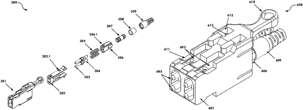
1. An optical fiber connector for being plugged into a receptacle, the optical fiber connector comprising:
a connector housing having opposite upper and lower sides spaced apart along a connector height and opposite left and right sides spaced apart along a connector width, the connector width being less than the connector height, the upper side of the connector housing defining a groove;
at least one optical fiber ferrule received in the connector housing, the at least one optical fiber ferrule configured to terminate at least two optical fibers and to hold the at least two optical fibers so that tips of the at least two optical fibers are spaced apart along the connector height; and
a push-pull latch release mechanism disposed on the upper wall of the connector housing, the push-pull latch release mechanism comprising a latch component and a remote release component, the latch component configured to latch with the receptacle when the optical fiber connector is plugged into the receptacle, the remote release component including a front section and a rear section, the front section configured to be received in the receptacle when the optical fiber connector is plugged into the receptacle, the rear section configured to extend out of the receptacle when the optical fiber connector is plugged into the receptacle, the front section being slidably constrained in the groove such that the front section can slide along the groove to actuate the latch component for unlatching from the receptacle when the remote release component is pulled rearward.
|