| CPC G01S 17/89 (2013.01) [G01S 7/4817 (2013.01); G01S 17/42 (2013.01); G01S 17/894 (2020.01); G02B 26/105 (2013.01)] | 19 Claims |

|
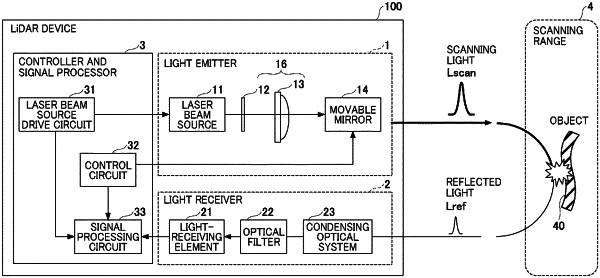
1. An optical device comprising:
a light source provided with a plurality of surface-emitting laser elements configured to emit a laser beam;
a scanner configured to scan the laser beam emitted from the light source; and
an optical system disposed in an optical path between the light source and the scanner and configured to guide the laser beam to the scanner,
the optical system including
a first optical element configured to reduce a divergence angle of the laser beam emitted from the light source, and
a second optical element configured to concentrate the laser beam that has passed through the first optical element onto a to-be-scanned surface of the scanner, wherein the scanner is located at a beam waist position that corresponds a focal point of the second optical element.
|