| CPC G01N 21/65 (2013.01) [G01N 21/64 (2013.01); G02B 21/0004 (2013.01); G02B 21/16 (2013.01); G02B 21/18 (2013.01); G02B 21/362 (2013.01); G02B 26/0816 (2013.01); G02B 27/1006 (2013.01); G02B 27/141 (2013.01); G01N 2201/0636 (2013.01); G01N 2201/06113 (2013.01); G01N 2201/084 (2013.01)] | 11 Claims |

|
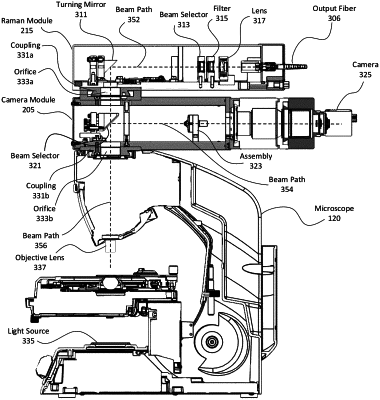
1. A module system configured to interface with a microscope, comprising, as a unitary Raman module:
an input optical fiber configured to provide an excitation light beam from an external light source;
a plurality of dynamic alignment mirrors, optically coupled with the input optical fiber, being configured to adjust the position of one or more beam paths of the excitation light beam, wherein the one or more beam paths are on a first plane;
a first coupling element comprising a first end configured to engage with a complementary end of a second coupling element on the microscope, thereby positioning the module system at a top of the microscope;
a turning mirror, optically coupled with the input optical fiber via the plurality of dynamic alignment mirrors the turning mirror being configured to reflect substantially all of the excitation light beam from a first beam path of the one or more beam paths on the first plane to a second beam path on a second plane through an orifice in the first and second coupling elements, wherein the first coupling element is configured to allow the module system to be selectively attached and detached from the microscope without altering the configuration of the microscope or any components of the microscope; and
an output optical fiber, optically coupled with a sample via the turning mirror and configured to receive light from the sample through the orifice, wherein the turning mirror is further configured to reflect substantially all of the light from the sample from the second beam path on the second plane to a third beam path of the one or more beam paths on the first plane.
|