| CPC G01D 5/3473 (2013.01) [H02K 1/22 (2013.01)] | 6 Claims |

|
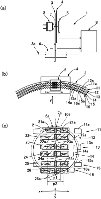
1. An optical rotary encoder comprising:
a rotating disc provided with a plurality of detection tracks that are formed concentrically;
a light-emitting element that irradiates the detection tracks with detection light;
a fixed slit plate provided with a slit pattern that allows passage of optical signals obtained from regions irradiated with the detection light in each of the detection tracks; and
a light-receiving element that receives each of the optical signals that have passed through the slit pattern,
wherein each of the detection tracks is configured from a slit or a reflective zone arranged at regular angular intervals;
the slit pattern in the fixed slit plate is configured from slit rows, the number of slit rows corresponding to the number of detection tracks;
the slit rows includes a plurality of first slit rows and a plurality of second slit rows, the first and second slit rows being lined up in the radial direction of the rotating disc;
the first slit rows have a slit-arrangement-direction length that is shorter than that of the second slit rows; and
the slit pattern is formed so that each of the first slit rows is positioned on both radial-direction sides, the radial direction being a direction in which the slit rows are lined up, and the slit pattern being positioned within an effective irradiation region of the detection light in the fixed slit plate.
|