| CPC F23R 3/286 (2013.01) [F23R 3/14 (2013.01); F23R 3/36 (2013.01)] | 13 Claims |

|
1. A method of injecting hydrogen into a combustion chamber of a combustor of a gas turbine system, the method comprising:
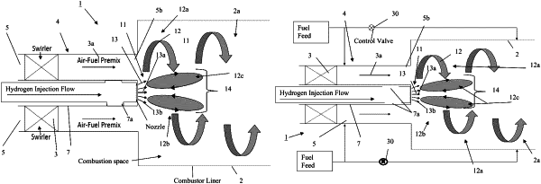
outputting a mixture of fuel and air into the combustion chamber via an outlet of an outer conduit in fluid communication with the combustion chamber to generate a first wake region; and
injecting at least one jet of hydrogen into the combustion chamber toward the first wake region via an outlet of an inner hydrogen injection conduit that is in fluid communication with the combustion chamber;
the outer conduit being positioned such that the outlet of the outer conduit is around an outer periphery of the outlet of the inner hydrogen injection conduit;
wherein the first wake region is downstream of the outlet of the inner hydrogen injection conduit and upstream of a position within the combustion chamber at which the mixture of fuel and air output from the outlet of the outer conduit crosses a discharge region of the outlet of the inner hydrogen injection conduit within the combustion chamber;
wherein a burner of the combustor includes the outer conduit and the injecting of the at least one jet of hydrogen into the combustion chamber via the outlet of the inner hydrogen injection conduit is performed to control operation of the gas turbine so that a ratio of hydrogen to fuel flow rate is provided so that an equivalence ratio for the combustor is equal to:
 where:
m,H2,central,max is a maximum allowable central hydrogen injection mass flow rate;
m,Fuel is a fuel flow rate of the fuel for the burner,
m,recirc is a mass flow recirculation rate in a first wake region of the burner;
m,total is a total burner flow rate; and
Φ is the equivalence ratio accounting for only the air and the fuel injected through the outlet of the outer conduit.
|