| CPC F23R 3/283 (2013.01) [F02C 3/00 (2013.01); F23R 3/50 (2013.01); F23R 3/60 (2013.01); F05D 2220/32 (2013.01); F05D 2230/60 (2013.01); F05D 2240/35 (2013.01); F23R 2900/00017 (2013.01)] | 9 Claims |

|
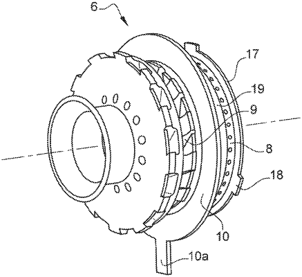
1. A combustion chamber for a turbomachine, comprising:
a bottom wall comprising at least one opening extending therethrough,
at least one sleeve mounted upstream of the bottom wall and fixed to the bottom wall, the sleeve having a cylindrical portion and a radially extending annular portion, a closing ring having a cylindrical portion and radial portion, wherein the cylindrical portion of the closing ring fits radially within the cylindrical portion of the sleeve and a downstream end of the cylindrical portion of the closing ring rests against the radially extending annular portion of the sleeve such that an annular groove is defined by the cylindrical and the radial portions of the closing ring and the radially extending annular portion of the sleeve,
at least one air and fuel injection system, having an axis, mounted in the opening of the bottom wall, the injection system comprising an annular flange extending radially with respect to said axis, mounted in said annular groove with a radial clearance,
a baffle situated downstream of the bottom wall, fixed to the sleeve and/or to the bottom wall, comprising a radially internal part situated axially between the bottom wall and a downstream end of the injection system,
wherein the injection system comprises at least one projecting part extending radially and configured to be introduced into one of a recessed part of the baffle and a first angular mounting position of the injection system with respect to the baffle, said projecting part being configured to come axially into abutment against a radial face or a downstream face of the baffle, or respectively, of the injection system, in a second angular position for holding the injection system with respect to the baffle, said projecting part being angularly offset from the recessed part in said second angular position, the injection system further comprising a rotation blocking lug extending from the annular flange and through a gap in the cylindrical portion of the sleeve such that the rotation blocking lug is immobilized in rotation by circumferential stops of the sleeve.
|