| CPC F21S 41/27 (2018.01) [F21S 41/147 (2018.01); F21S 41/321 (2018.01); F21S 41/43 (2018.01)] | 20 Claims |

|
1. An optical system (1) for a motor vehicle headlight, wherein the optical system (1) comprises:
at least two optical elements (2a, 2b) and the at least two optical elements respectively comprising:
a light coupling area (3), for coupling light beams into the optical element (2a, 2b),
a light decoupling area (4), for decoupling the light beams coupled into the optical element (2a, 2b), wherein the light decoupling area (4) is configured as a projection lens (4a), which projection lens (4a) has an optical axis (x) and a focal surface (f), and
a lateral surface (5) delimiting the optical element (2a, 2b) for deflecting the light beams coupled into the optical element (2a, 2b), the lateral surface (5) extends between the light coupling area (3) and the light decoupling area (4), wherein a section of the lateral surface (5) is configured as a beam aperture (6) with an optically effective aperture edge (6a), wherein the optically effective aperture edge (6a) is designed so as to form a bright/dark boundary in a far-field light distribution producible with the optical system, wherein the section of the lateral surface (5) configured as a beam aperture (6) lies in a defined plane,
wherein the projection lens (4a) and the beam aperture (6) are arranged relative to each other in such a manner that the optical axis (x) of the projection lens (4a) lies in the defined plane and the optically effective aperture edge (6a) of the beam aperture (6) lies in the focal surface (f) of the projection lens (4a),
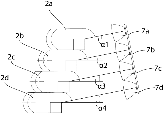
wherein the optical elements (2a, 2b) include at least two anterior optics (7a, 7a), wherein one anterior optic (7a, 7b) is associated with each optical element (2a, 2b), wherein each anterior optic (7a, 7b) includes a light source and is configured to direct light from the light source onto the light coupling area (3) of the optical element (2a, 2b) associated with it, wherein:
a first anterior optic (7a) of the at least two anterior optics (7a, 7b) is configured to direct light beams of the light source associated with it in the form of a first light beam bundle along a first coupling direction onto the light coupling area (3) of a first optical element (2a) associated with it, wherein the first light beam bundle is bundled after the coupling via the light coupling area (3) into an area of the optically effective aperture edge (6a) of the first optical element (2a) in such a manner that the first light beam bundle exhibits its highest light beam density at the optically effective aperture edge (6a), in a sectional plane orthogonal to the optical axis of the first optical element (2a), wherein a first part of the first light beam bundle is blocked by the beam aperture (6) and a second part of the first light beam bundle passes the aperture edge (6a) and propagates in the direction of the projection lens (4a), wherein the first coupling direction is oriented at a first coupling angle (α1) relative to the optical axis of the first optical element (2a),
a second anterior optic (7b) of the at least two anterior optics (7a, 7b) is configured to direct light beams of the light source associated with it in the form of a second light beam bundle along a second coupling direction onto the light coupling area (3) of the optical element (2b) associated with it, wherein the second light beam bundle is bundled after the coupling via the light coupling area (3) into an area of the optically effective aperture edge (6a) of the optical element (2b) in such a manner that the second light beam bundle exhibits its highest light beam density at the optically effective aperture edge (6a), in a sectional plane orthogonal to the optical axis of the optical element (2b), wherein a first part of the second light beam bundle is blocked by the beam aperture (6) and a second part of the second light beam bundle passes the aperture edge (6a) and propagates in the direction of the projection lens (4a), wherein the second coupling direction is oriented at a second coupling angle (α2) relative to the optical axis of the optical element (2b),
the first anterior optic (7a) and the first optical element (2a) are designed and configured to irradiate the first light beam bundle that forms a first far-field light distribution, wherein the first far-field light distribution exhibits a bright/dark boundary which is straight at least in sections and which lies below an HH line, and
the second anterior optic (7b) and the second optical element (2b) are designed and configured to irradiate the second light beam bundle that forms a second far-field light distribution, wherein the second far-field light distribution lies below the bright/dark boundary of the first far-field light distribution.
|