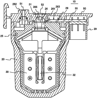
| CPC F16K 31/008 (2013.01) [F16K 1/54 (2013.01); F16K 27/029 (2013.01); F16K 31/007 (2013.01); F16K 2200/50 (2021.08)] | 10 Claims |

|
1. A piezoelectric valve comprising:
a valve main part including a gas pressure chamber that receives compressed gas supplied from an outside;
a plate disposed inside the valve main part; and
an actuator, fixed to the plate and disposed inside the valve main part together with the plate, including a valve element that opens and closes a gas discharge path for discharging compressed gas from the gas pressure chamber, a laminated piezoelectric element that generates a driving force as a displacement, and a displacement enlargement mechanism, the driving force being required for operation of the valve element, the displacement enlargement mechanism enlarging the displacement of the laminated piezoelectric element and causing the enlarged displacement to act on the valve element,
wherein the valve main part is a case with an opening on a front surface;
the plate is provided with the gas discharge path and a valve seat with which the valve element of the actuator comes into contact, the actuator opening and closing the gas discharge path; and
a lid member that closes the opening of the case has a gas discharge opening communicating with the gas discharge path of the plate, is welded and fixed without a gasket to a front surface of the plate on an annular welded part surrounding the gas discharge opening, and is welded and fixed without a gasket to an end surface of the case on an annular welded part on an outer peripheral part, the front surface of the plate being a surface where the gas discharge path opens.
|