| CPC F16D 23/12 (2013.01) [F16H 37/124 (2013.01); H02K 7/108 (2013.01); H02K 7/116 (2013.01); F16D 13/52 (2013.01); F16D 2023/123 (2013.01); F16D 2125/36 (2013.01); F16D 2125/50 (2013.01)] | 6 Claims |

|
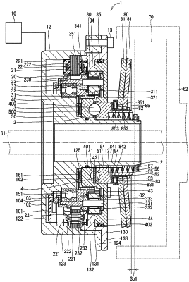
1. A clutch device comprising:
a housing;
a prime mover including a stator fixed to the housing, and a rotor relatively rotatable relative to the housing, the prime mover being capable of outputting torque from the rotor;
a speed reducer configured to output the torque of the prime mover at a reduced speed;
a rotational translation unit including a rotation portion configured to be rotatable relative to the housing upon receiving an input of the torque output from the speed reducer, and a translation portion configured to move relative to the rotation portion and the housing in an axial direction in accordance with rotation of the rotation portion relative to the housing;
a clutch disposed between a first transmission portion and a second transmission portion that are rotatable relative to the housing, the clutch being configured to allow transmission of torque between the first transmission portion and the second transmission portion in an engaged state of the clutch, and to interrupt the transmission of the torque between the first transmission portion and the second transmission portion in a disengaged state of the clutch; and
a state changing unit configured to receive a force along the axial direction from the translation portion and change a state of the clutch to the engaged state or the disengaged state according to a position of the translation portion in the axial direction relative to the housing, wherein
the speed reducer includes
a sun gear coaxial and integrally rotatable with the rotor,
planetary gears disposed in a circumferential direction of the sun gear and configured to revolve in the circumferential direction of the sun gear while rotating in a state of meshing with the sun gear,
a carrier rotatably supporting the planetary gears and being rotatable relative to the sun gear,
a first ring gear fixed to the housing and including a first ring gear tooth portion capable of meshing with the planetary gears, and
a second ring gear rotatable integrally with the rotation portion and including a second ring gear tooth portion capable of meshing with the planetary gears, the second ring gear tooth portion being different in number of teeth from the first ring gear tooth portion, and
the translation portion is non-rotatable relative to the housing;
the rotor and the rotation portion are coaxial.
|