| CPC F02N 5/02 (2013.01) [F02N 5/04 (2013.01); F02N 15/022 (2013.01); F02N 2200/022 (2013.01)] | 3 Claims |

|
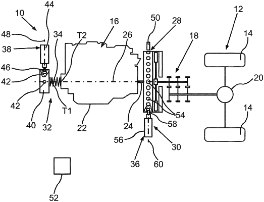
1. An internal combustion engine (16) of a motor vehicle, comprising:
an output shaft (24) which is rotatable around an axis of rotation (26) relative to a housing (22) of the internal combustion engine (16), wherein a torque is providable by the internal combustion engine (16) for driving the motor vehicle via the output shaft (24);
a spring element (34) which is rotatable with the output shaft (24), wherein the spring element (34) is tensionable as a result of a deactivation of the internal combustion engine (16) by rotation of the output shaft (24) relative to the housing (22) around the axis of rotation (26), wherein a spring force is providable by the spring element (34) by tensioning the spring element (34), wherein the output shaft (24) is settable in rotation relative to the housing (22) around the axis of rotation (26) during a start of the internal combustion engine (16) following the deactivation by the spring force, and wherein the spring element (34) has a first part (T1) and has a second part (T2) that is non-rotationally connected to the output shaft (24);
a locking device (36), wherein the output shaft (24) is securable against rotation relative to the housing (22) around the axis of rotation (26) after the spring element (34) has been tensioned and while the spring element (34) is tensioned by the locking device (36);
a blocking device (38), wherein the blocking device (38) is adjustable between a first blocking state securing the first part (T1) of the spring element (34) against a rotation taking place relative to the housing (22) around the axis of rotation (26) and a first release state releasing the first part (T1) for a rotation taking place relative to the housing (22) around the axis of rotation (26);
a blocking element (40), wherein the blocking element (40) is formed separately from the spring element (34) and is non-rotationally connected to the first part (T1) of the spring element (34) and interacts in the blocked state with the blocking device (38), wherein the blocking element (40) and, via the blocking element (40), the first part (T1) of the spring element (34) are securable against a rotation taking place in relation to the housing (22) around the axis of rotation (26);
wherein the locking device (36) is movable between a second blocking state securing the output shaft (24) against rotation taking place in relation to the housing (22) around the axis of rotation (26) and a second release state releasing the output shaft (24) for rotation taking place in relation to the housing (22) around the axis of rotation (26); and
a flywheel (28) formed separately from the output shaft (24), wherein the flywheel (28) is rotatable together with the output shaft (24) and wherein the locking device (36) cooperates in a form-fit manner with the flywheel (28) in the second blocking state;
wherein the flywheel (28) and the blocking element (40) are disposed on respective sides (30, 32) of the output shaft (24) which are opposite one another in an axial direction of the output shaft (24).
|