| CPC E04G 21/123 (2013.01) [B25B 27/146 (2013.01); E04G 21/122 (2013.01)] | 13 Claims |
|
1. A kit for a rebar fastener gun, comprising:
a body having a linear actuator disposed therein, the linear actuator activatable by a user through a trigger on the body or a sensor that detects a downward force placed on the body against an object,
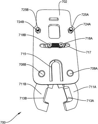
a head capable of being attached or removed from the body, the head comprising:
a base plate;
two arms attached to the base plate by way of pivots and capable of partial rotation therearound, the arms defining a hollow channel running therebetween, wherein the arms terminate at jaw portions designed to surround two rebar rods to be joined together, wherein the arms have first and second offset grooves disposed on their inner surfaces and in communication with the hollow channel;
a shaft having a first end designed to attach to an end of the linear actuator;
a hammer designed to fit at a second end of the shaft, the hammer having a narrow end designed to mate with the hollow channel running between the two arms, the narrow end of the hammer terminating at a groove running at an offset angle relative to a line w defining the width of the hammer, the hammer groove set at an angle designed to hold a U-shaped staple in a manner where a mechanical force exerted on the hammer by way of the actuator through the shaft feeds a first end of the U-shaped staple through the first offset groove and a second end of the staple through the second offset groove; and
a track designed to hold a set of U-shaped staples and feed the staples through a U-shaped opening in the base plate of the head as a result of a force applied to the set of U-shaped staples, wherein the track comprises:
a frame comprising an endplate and first and second sides attached to the endplate;
an axial shaft extending from the endplate and between the first and second sides;
an axial spring surrounding the axial shaft;
a first mechanism designed to adjust the distance between the first and second sides;
a second mechanism designed to lock the axial spring in place in a compressed position or unlock the axial spring in an extended position; and
a horseshoe-shaped member comprising first and second arms and having a curved wire underneath exerting pressure pushing the first and second arms away from each other to cause a first and second side of the frame to have a distance therebetween exceeding a width of the width of the U-shaped staples.
|