| CPC E04F 15/02038 (2013.01) [E04F 13/08 (2013.01); E04F 15/02033 (2013.01); E04F 15/102 (2013.01); E04F 15/105 (2013.01); E04F 15/107 (2013.01); E04F 2201/0107 (2013.01); E04F 2201/0146 (2013.01); E04F 2201/0153 (2013.01); E04F 2201/0161 (2013.01); E04F 2201/023 (2013.01)] | 20 Claims |

|
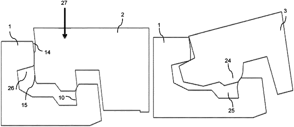
1. A set of panels comprising a first panel and a second panel, said first and second panel each having a first edge, a second edge and a third edge and wherein the first edge of the first panel is configured to be able to be locked together with both the second edge and the third edge, respectively, of the second panel,
wherein the first edge comprises a first locking element configured to be able to cooperate with a first locking groove at the second edge and a second locking groove at the third edge, respectively, for locking in a horizontal direction,
wherein the first edge further comprises a tongue groove configured to cooperate with a tongue at the second edge and a tongue at the third edge, respectively, for locking in a vertical direction,
wherein the second edge of the second panel is configured to be connected vertically to the first edge of the first panel,
wherein the third edge is configured to be assembled to the first edge by an angling motion,
wherein the first locking element comprises a first locking surface which is configured to cooperate with a second locking surface on the first locking groove,
wherein the first locking element comprises a third locking surface which is configured to cooperate with a fourth locking surface on the second locking groove, for locking in the horizontal direction, and
wherein the first locking surface is positioned below the third locking surface.
|