| CPC C23C 16/45572 (2013.01) [C23C 16/4583 (2013.01); C23C 16/46 (2013.01)] | 20 Claims |

|
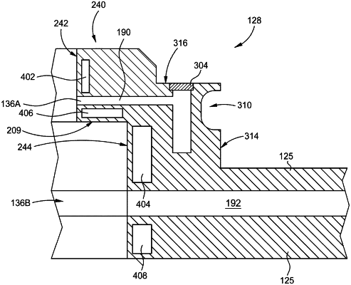
1. An injector apparatus, comprising:
an injector body;
a first arcuate surface of the injector body, the first arcuate surface having a first outlet formed therein, the first outlet in fluid communication with a first conduit formed within the injector body;
a second arcuate surface of the injector body substantially parallel to the first arcuate surface and offset from the first arcuate surface, the second arcuate surface having a second outlet formed therein, the second outlet in fluid communication with a second conduit formed within the injector body;
a third surface of the injector body, the third surface having a third outlet formed therein, the third outlet in fluid communication with a third conduit formed within the injector body, wherein the third surface is substantially normal to the first arcuate surface and the second arcuate surface and the third outlet is substantially normal to the first outlet and the second outlet;
a first cooling channel formed in the injector body, the first cooling channel having:
a first portion of the first cooling channel disposed around a first side of the first conduit, wherein the first portion of the first cooling channel is adjacent the first arcuate surface; and
a second portion of the first cooling channel disposed around a second side of the second conduit, wherein the second portion of the first cooling channel is adjacent the first arcuate surface and the second arcuate surface; and
a second cooling channel formed in the injector body, the second cooling channel having:
a first portion of the second cooling channel disposed around a first side of the second conduit, wherein the first portion of the second conduit is adjacent the second arcuate surface; and
a second portion of the second cooling channel disposed around a second side of the second conduit opposite the first side of the second conduit, wherein the second portion of the second cooling channel is adjacent the second arcuate surface.
|