| CPC B67D 1/0012 (2013.01) [B67D 1/0082 (2013.01); B67D 1/0855 (2013.01); B67D 2001/0094 (2013.01); B67D 2001/0097 (2013.01); B67D 2210/00052 (2013.01)] | 19 Claims |

|
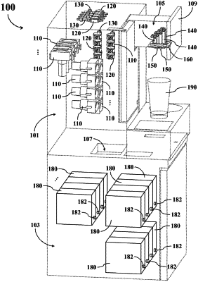
1. A material dispensing device (400) for dispensing liquid material whose viscosity is higher than water, the material dispensing device (400) comprising:
a pump (110), arranged to operably pressure liquid material whose viscosity is higher than water to push the liquid material forward;
a damper device (120), arranged to operably buffer liquid material flowing through the damper device (120); and
a material output tube (140);
wherein the damper device (120) comprises:
a damper base (420), comprising a material entrance hole (421), a material exit hole (423), and a material buffer chamber (425) located between the material entrance hole (421) and the material exit hole (423), wherein the material entrance hole (421) is arranged to operably transmit received liquid material to the material buffer chamber (425), the material buffer chamber (425) is arranged to temporarily store the liquid material flowing into the material buffer chamber (425), and the material exit hole (423) is arranged to operably output the liquid material passed through the material buffer chamber (425);
a block element (429), positioned in the material buffer chamber (425) and located in a straight path between the material entrance hole (421) and the material exit hole (423), arranged to operably prevent the liquid material from directly flowing from the material entrance hole (421) to the material exit hole (423) in a straight line path;
a diaphragm (430), covered on the material buffer chamber (425); and
a fastening element (440), positioned on the diaphragm (430) and having a hollow portion (442);
wherein when a volume of the liquid material within the material buffer chamber (425) exceeds a predetermined amount, the diaphragm (430) deforms to protrude outward, so that a part of the diaphragm (430) enters the hollow portion (442) of the fastening element (440).
|