|
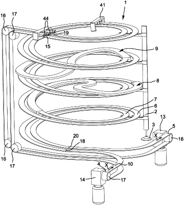
1. An accumulating conveyor, comprising a first helical track and a second helical track including coincident centerlines, a first S-shaped bridge and a second S-shaped bridge, each having a first bend in one direction and a second bend in opposite direction as seen from above, a first set of auxiliary guides and a second set of auxiliary guides and a single endless conveyor belt which is drivable in a direction of conveyance, wherein the single conveyor belt is guidable by said first and second helical tracks, the first and second bridges and the first and second sets of auxiliary guides such that under operating conditions the single conveyor belt successively follows the first helical track from a lower end thereof in upward direction to a location below an upper end thereof, the first bridge to a location at the second helical track below an upper end thereof, the second helical track in downward direction to a lower end thereof, the first set of auxiliary guides to the upper end of the second helical track, the second helical track in downward direction, the second bridge to the first helical track, the first helical track in upward direction to the upper end thereof, and the second set of auxiliary guides to the lower end of the first helical track, wherein the first and second bridges are at least partly located at a common inner side of the first and second helical tracks and synchronously movable along the first and second helical tracks for varying the effective lengths of the single conveyor belt between the lower ends of the first and second helical tracks via the first bridge, on the one hand, and between the upper ends of the first and second helical tracks via the second bridge, on the other hand, wherein at least portions of the first and second bends of at least one of the first and second bridges bank to their insides.
|
