| CPC B60T 1/065 (2013.01) [F16D 55/40 (2013.01)] | 19 Claims |

|
1. A braking system for a portal lift assembly for an all-terrain vehicle or a utility task vehicle, the system comprising:
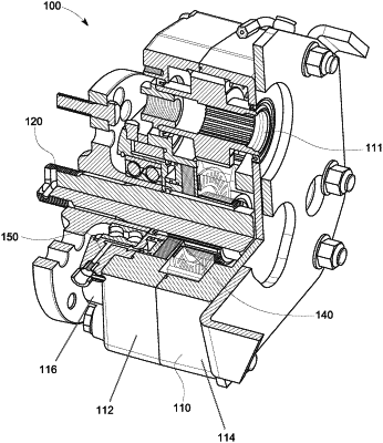
a) a portal box housing having a stock axle receptacle adapted to receive a stock axle shaft of an off-road vehicle, wherein the portal box housing defines a first opening;
b) a linking mechanism housed in said portal box housing and effective for linking the stock axle received in the stock axle receptacle to an output shaft, wherein the linking mechanism comprises an input gear, an output gear, and a linking gear contained in the housing;
c) an output shaft operably connectable via said linking mechanism to a stock axle received in the stock axle receptacle, and effective to rotate upon rotation of the stock axle, wherein the output shaft extends through the first opening;
d) a piston positioned at a first position in the portal box housing along or around said output shaft and effective for applying an axial force in a first direction along the axis of the output shaft;
e) a fluid channel fillable with a non-compressible fluid and effective to apply a hydraulic force to said piston when pressure is applied to fluid in the line, thereby moving the piston axially in said first direction along the axis of the shaft;
f) a pressure plate positioned at a second position in the portal box housing along or around said output shaft and effective for applying an axial force in a second direction opposite said first direction along the axis of the output shaft in response to the application of an axial force in said first direction by said piston;
g) a clutch pack positioned in the portal box housing between said pressure plate and said piston, said clutch pack comprising a first set of clutch plates radially surrounding a portion of said shaft, and a second set of clutch plates radially surrounding a portion of said shaft,
wherein the first set of clutch plates is splined directly to the output shaft in a manner effective to cause those clutch plates to rotate about the axis of the shaft when the shaft rotates, and
wherein the second set of clutch plates are rotationally coupled to the portal box housing which prevents the second set of clutch plates from rotating about the axis of the shaft, and
wherein members of the first set of clutch plates are interspersed between members of the second set of clutch plates, so that when the clutch pack is sufficiently compressed by axial forces applied by said piston and said pressure plate, the first set of clutch plates is forced against the second set of clutch plates so that friction forces between members of the first set of clutch plates and members of the second set of clutch plates slow and may subsequently stop the rotation of the shaft, and
wherein the clutch pack is selectively insertable and removable through the first opening over the output shaft.
|