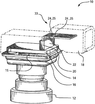
| CPC B60R 11/04 (2013.01) [H04N 23/51 (2023.01); H04N 23/55 (2023.01)] | 23 Claims |

|
1. A vehicular camera, the vehicular camera comprising:
a camera housing comprising a first portion and a second portion joined together to form a cavity within the camera housing;
wherein the first portion comprises a lens barrel that accommodates a lens;
an imager disposed in the cavity and aligned with the lens, wherein the imager comprises a CMOS imager;
a circuit board having a first side and a second side separated by a thickness of the circuit board;
wherein a first electrical connector is disposed at the second side of the circuit board, and wherein the first electrical connector is in electrically-conductive connection with the imager, and wherein the first electrical connector comprises a plurality of pin-receiving sockets;
wherein the second portion of the camera housing has a second electrical connector, and wherein the second electrical connector comprises a plurality of pins, each individual pin of the plurality of pins including a first end and a second end opposite the first end;
wherein, with the first portion of the camera housing joined with the second portion of the camera housing to form the cavity within the camera housing, the first ends of the individual pins of the plurality of pins are disposed within the cavity and the second ends of the individual pins of the plurality of pins are disposed outside of the cavity;
wherein, when the second portion of the camera housing is being joined with the first portion of the camera housing, respective first ends of individual pins of the plurality of pins of the second electrical connector of the second portion insert into and electrically-conductively connect with respective individual pin-receiving sockets of the plurality of pin-receiving sockets of the first electrical connector at the second side of the circuit board;
wherein the first electrical connector and the second electrical connector cooperate to allow for misalignment of the second electrical connector relative to the first electrical connector when the second portion of the camera housing is being joined with the first portion of the camera housing; and
wherein the second ends of the individual pins of the plurality of pins of the second electrical connector are configured to electrically-conductively connect to a vehicle wire harness when the vehicular camera is mounted at a vehicle.
|