| CPC B23K 20/128 (2013.01) [B23K 20/1255 (2013.01); B23K 20/1265 (2013.01); B23K 2103/10 (2018.08)] | 4 Claims |

|
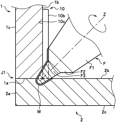
1. A joining method by which a first metal member and a second metal member are joined to each other with use of a rotary tool,
wherein the rotary tool is provided with a base side pin and a tip side pin, the tip side pin has a spiral groove on an outer circumferential face thereof, the base side pin does not have a spiral groove on the outer circumferential face which is smooth, and a tapered angle of the base side pin is larger than a tapered angle of the tip side pin, the method comprising:
a butting process in which the first metal member and the second metal member are butted against each other so as to have an almost L-shaped or T-shaped cross section to form a butted portion;
a disposing process in which one auxiliary member is disposed at an inner corner portion formed of the first metal member and the second metal member so that the one auxiliary member is brought into face-to-face contact with the first metal member or the second metal member; and
a friction stirring process in which the first metal member, the second metal member, and the auxiliary member are joined to one another by moving the rotary tool along the inner corner portion in a state where the tip side pin which is being rotated is inserted into the inner corner portion, is in contact with the first metal member, the second metal member, and the auxiliary member, and the outer circumferential face of the base side pin is pressed against the auxiliary member.
|