| CPC B23K 20/1255 (2013.01) | 1 Claim |

|
1. A joining method of welding a first metal member and a second metal member using a rotary tool with a stirring pin, comprising:
a preparation step of forming a first step bottom surface and a first step side surface in a front surface of an end portion of the first metal member, and forming a second step bottom surface and a second step side surface in a back surface of an end portion of the second metal member;
a superposition butting step of forming a lap section by stacking the first step bottom surface and the second step bottom surface together, forming a front-side butt section by butting the first step side surface and an end surface of the second metal member together, and forming a back-side butt section by butting the second step side surface and an end surface of the first metal member together; and
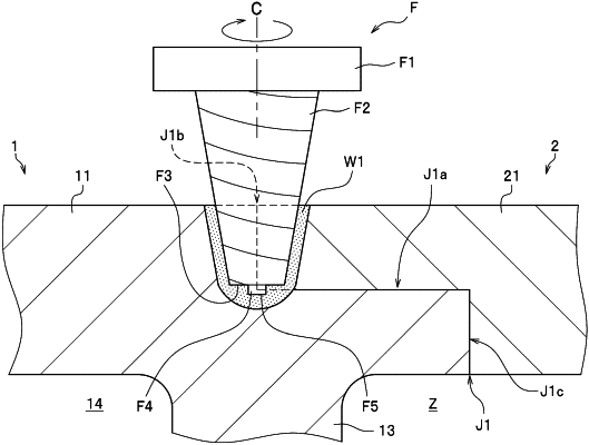
a friction stirring step of welding the back-side butt section and the lap section by inserting the stirring pin, as rotating, from the back-side butt section, and by relatively moving the rotary tool along the back-side butt section with only the stirring pin put in contact with the first metal member and the second metal member, wherein
the stirring pin includes a flat surface normal to an axis of rotation of the rotary tool, and a protruding section projecting from the flat surface, and
in the friction stirring step, the back-side butt section and the lap section are welded with the flat surface inserted into the first metal member and the second metal member, and with a distal end surface of the protruding section inserted deep beyond the lap section and the lap section is located at a same depth as a depth at which an outer peripheral side surface of the protruding section is positioned.
|