| CPC B05B 7/2416 (2013.01) [B05B 7/0081 (2013.01); B05B 7/068 (2013.01); B05B 7/2424 (2013.01); B05B 7/2437 (2013.01); B05B 7/2478 (2013.01); B05B 12/00 (2013.01); B05B 12/002 (2013.01); B05B 12/085 (2013.01); G05D 16/2066 (2013.01); B05B 7/0815 (2013.01); B05B 7/247 (2013.01); B05B 7/2472 (2013.01); B05B 7/2481 (2013.01); F04D 17/16 (2013.01); F04D 25/06 (2013.01); F04D 27/004 (2013.01)] | 4 Claims |

|
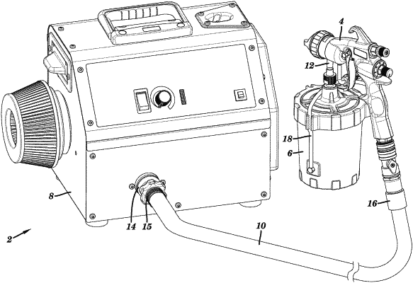
1. A sprayer comprising:
a fluid reservoir configured to hold a spray fluid;
a motor;
a turbine that is rotated by the motor to generate a flow of pressurized air;
a hose having a first end and a second end, the first end receiving the pressurized air output by the turbine;
a spray gun having a trigger and a valve, the fluid reservoir mounted to the spray gun, the second end of the hose connected to the spray gun, wherein actuation of the trigger causes the valve to open and the spray gun to spray the spray fluid from the fluid reservoir using the pressurized air from the hose;
a pressure sensor that outputs a signal indicative of air pressure in a pneumatic circuit that connects the turbine to the spray gun; and
control circuitry that receives the signal and regulates an electrical power output that is delivered to the motor, the control circuitry configured to:
start a timer based on the signal indicating that the air pressure within the pneumatic circuit is above the threshold pressure, wherein the control circuitry continues to deliver the electrical power output to the motor to cause the turbine to output the flow of pressurized air to the pneumatic circuit during counting of the timer,
continue delivery of electrical power output to the motor to cause the turbine to output the flow of pressurized air to the pneumatic circuit after expiration or termination of the timer if the signal indicates that the air pressure within the pneumatic circuit dropped below the threshold pressure during counting of the timer,
reduce the electrical power output to the motor to stop the turbine from outputting the flow of pressurized air based on the signal indicating that the air pressure within the pneumatic circuit remained above the threshold pressure during counting of the timer, and
increase the electrical power output to the motor to restart the motor to resume the turbine outputting the flow of pressurized air to the pneumatic circuit based on the signal indicating that the air pressure in the pneumatic circuit dropped below the threshold pressure.
|